


Free-Standing
Fireplaces
RFS22
RFS32
RFS42
Installation Instructions & Homeowner's Manual
WARNING! IF THE INFORMATION IN THIS MANUAL IS NOT FOLLOWED EXACTLY, A FIRE OR EXPLOSION MAY RESULT CAUSING PROPERTY DAMAGE, PERSONAL INJURY OR LOSS OF LIFE.
FOR YOUR SAFETY
WHAT TO DO IF YOU SMELL GAS:
•Do not try to light any appliance.
•Do not touch any electric switch
•Do not use any phone in your building.
•Immediately call your gas supplier from your neighbours phone. Follow the gas suppliers instructions.
•If you cannot reach your gas supplier call the fire department.
FOR YOUR SAFETY
DO NOT STORE
OR USE GASOLINE OR OTHER FLAMMABLE VAPOURS AND LIQUIDS IN THE VICINITY OF THIS OR ANY OTHER APPLIANCE.
•Installation and service must be performed by a qualified installer, Service agency or your gas supplier.
The Vermont Castings
Majestic Products Company
410 Admiral Blvd., Mississauga
Ontario, Canada L5T 2N1 www.majesticproducts.com / www.vermontcastings.com
INSTALLER: DO NOT DISCARD THIS MANUAL - LEAVE FOR HOMEOWNER |
10000834 |
11/01 Rev. 2 |

TABLE OF CONTENTS
PLEASE READ THE INSTALLATION & OPERATING INSTRUCTIONS BEFORE USING APPLIANCE.
Thank you and congratulations on your purchase of a Majestic fireplace
IMPORTANT: Read all instructions and warnings carefully before starting installation. Failure to follow these instructions may result in a possible fire hazard and will void the warranty.
Installation Instructions...................................................................................................... |
3 |
Important Curing/Burn Information ....................................................................... |
3 |
Locating Your Fireplace ........................................................................................ |
3 |
Clearance to Combustibles .................................................................................. |
3 |
Fireplace Dimensions ........................................................................................... |
4 |
Gas Specifications ................................................................................................ |
5 |
Preparation ........................................................................................................... |
5 |
Gas Line Installation ............................................................................................. |
5 |
Installation of Remote Switch for RN/RP gas valve .............................................. |
6 |
Fan Kit .................................................................................................................. |
6 |
General Venting Information ............................................................................................. |
7 |
Common Flue Installation ..................................................................................... |
7 |
Retrofitting to an Existing Brick Chimney ............................................................. |
8 |
Vent Safety System .............................................................................................. |
8 |
Proper Vent Performance ..................................................................................... |
8 |
Combustion Air ..................................................................................................... |
8 |
Operating Instructions ....................................................................................................... |
9 |
General Glass Information .................................................................................... |
9 |
Louvre Removal ................................................................................................... |
9 |
Trim Removal ....................................................................................................... |
9 |
Glass Removal ..................................................................................................... |
9 |
Glass Cleaning ................................................................................................... |
10 |
Installation of Logs and Burner Lava Rock ......................................................... |
10 |
Maintenance ....................................................................................................... |
10 |
Cleaning Procedure ............................................................................................ |
11 |
Flame Adjustment & Characteristics .................................................................. |
11 |
Ceramic Refractory ............................................................................................. |
11 |
Lighting Instructions ............................................................................................ |
12 |
Troubleshooting Gas Control (SIT 630) .............................................................. |
13 |
Troubleshooting Gas Control (SIT 820) .............................................................. |
14 |
Troubleshooting Gas Control (Honeywell) .......................................................... |
15 |
Replacement Parts List .............................................................................................. |
16 |
Replacement Parts Pictorial ............................................................................... |
17 |
Options 18 |
|
- 2 -
INSTALLATION INSTRUCTIONS
This gas fireplace should be installed by a qualified installer in accordance with local building codes and with current CAN / CGA-B149 (. 1 or .2) Installation codes for Gas Burning Fireplaces and Equipment.
FOR U.S.A Installations follow local codes and/or the current National Fuel Gas Code. ANSI Z223.1.
FOR SAFE INSTALLATION AND OPERATION OF YOUR MAJESTIC FIREPLACE PLEASE NOTE THE FOLLOWING:
1.This fireplace gives off high temperatures and should be located out of high traffic areas and away from furniture and draperies.
2.Children and adults should be alerted to the hazards of the high surface temperatures of this fireplace and should stay away to avoid burns or ignition of clothing.
3.Children should be carefully supervised when they are in the same room as your fireplace.
4.Under no circumstances should this fireplace be modified. Parts removed for servicing should be replaced prior to operating this fireplace again.
5.Installation and any repairs to this fireplace should be carried out by a qualified service person. A professional service person should be contacted to inspect this fireplace annually. Make it a practice to have all of your gas fireplaces checked annually. More frequent cleaning may be required due to excess lint and dust from carpeting, bedding material, etc.
6.Control compartments, burners and air passages in this fireplace should be kept clean and free of dust and lint. Make sure that the gas valve and pilot light are turned off before you attempt to clean this fireplace.
7.The venting system(chimney) of this fireplace should be checked at least once a year and if needed your venting system should be cleaned.
8.Keep the area around your fireplace clear of combustible materials, gasoline and other flammable vapour and liquids. This fireplace should not be used as a drying rack for clothing, nor should Christmas stockings or decorations be hung in the area of it.
9.Under no circumstances should any solid fuels (wood, coal, paper or cardboard etc.)be used in this fireplace.
10.The flow of combustion and ventilation air must not be obstructed in any way.
11.When the fireplace is installed directly on carpeting, vinyl tile or any combustible material other than wood, the fireplace must be installed on a metal or wood panel extending the full width and depth of the fireplace.
12.This fireplace requires adequate ventilation and combustion air to operate properly.
13.This fireplace must not be connected to a chimney flue serving a separate solid fuel burning fireplace.
IMPORTANT:
PLEASE REVIEW THE FOLLOWING CAREFULLY
Remove any plastic from trim parts before turning the fireplace ON.
It is normal for fireplaces fabricated of steel to give off some expansion and/or contraction noises during the start up or cool down cycle. Similar noises are found with your furnace heat exchanger or car engine.
It is not unusual for your Majestic gas fireplace to give off some odour the first time it is burned. This is due to the curing of the paint and any undetected oil from the manufacturing process.
Please ensure that your room is well ventilated - open all windows.
It is recommended that you burn your Majestic fireplace for a least six (6) hours the first time you use it. If optional fan kit has been installed, place fan in the "OFF" position during this time.
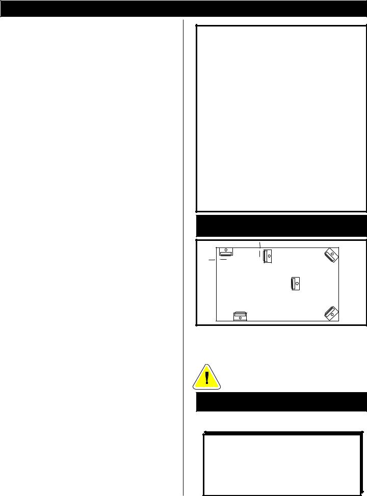
LOCATING YOUR MAJESTIC
GAS FIREPLACE
|
12" |
|
|
A |
(305mm) |
B |
D |
12" (305mm) |
|
||
|
|
|
|
|
|
|
C |
E |
|
|
F |
|
|
|
Fig. 1 |
A) *Flat on wall corner |
B) |
*Room divider |
C) Island |
D) |
Cross corner |
E)Flat on wall
*A & B must maintain a 12" (305mm) clearance between the wall and side glass of fireplace.
A minimum 12 foot vent height is required to effectively vent this fireplace.
CLEARANCES TO COMBUSTIBLES
Adequate clearances as listed below must be maintained for servicing and proper operation.
BACK... ...................................... |
1" |
SIDES.. .................................... 12" |
|
COMBUSTIBLE FLOOR.. .......... 0" |
|
TOP.... ...................................... |
36" |
CORNER ............ |
0" to back edges |
Flue Pipe Clearances - 6" Single Wall, 1"B" Vent.
- 3 -
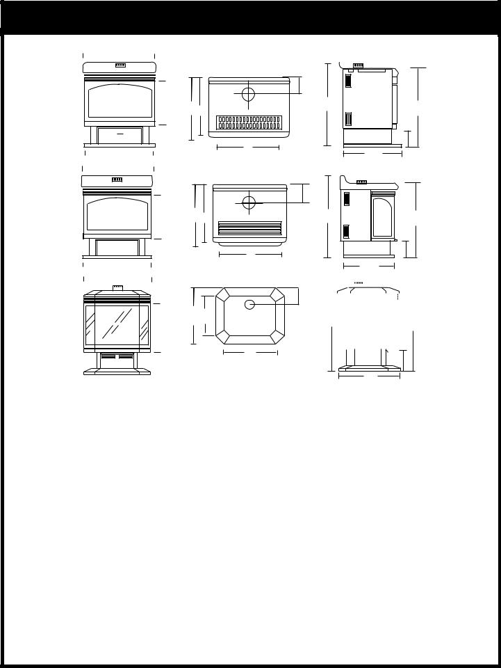
FIREPLACE DIMENSIONS
A
C
B
A
C
B
A
C
|
|
|
B |
|
|
|
|
|
|
||
|
MODEL RFS22 |
||||
A |
26" |
|
660mm |
||
|
|
|
|
|
|
B |
26" |
|
660mm |
||
|
|
|
|
|
|
C |
15 1/4" |
|
387mm |
||
D |
19 1/4" |
|
488mm |
||
E |
18 5/8" |
|
473mm |
||
F |
21" |
|
533mm |
||
|
|
|
|
|
|
G |
31 1/2" |
|
800mm |
||
H |
17 3/4" |
|
451mm |
||
I |
29 5/8" |
|
752mm |
||
J |
95/8" |
|
244mm |
||
K |
5 1/4" |
|
133mm |
||
L |
– |
|
– |
||
|
|
|
|
|
|
M |
– |
|
– |
||
|
|
|
|
|
|
N |
– |
|
– |
||
|
|
|
|
|
|
K
D E
F
MODEL RFS22
K
D E
F
MODEL RFS32
K
D M
N
MODEL RFS42
MODEL RFS32
A |
25" |
635mm |
|
|
|
B |
24 1/8" |
613mm |
C |
16" |
406mm |
|
|
|
D |
20" |
508mm |
|
|
|
E |
19" |
483mm |
|
|
|
F |
21" |
533mm |
|
|
|
G |
31 3/4" |
806mm |
H |
17 3/4" |
451mm |
I |
29 5/8" |
752mm |
J |
9" |
229mm |
|
|
|
K |
5 1/4" |
133mm |
L |
– |
– |
|
|
|
M |
– |
– |
|
|
|
N |
– |
– |
|
|
|
G I
J
H
G |
I |
J
H
|
|
|
|
|
|
|
|
|
|
|
|
|
|
|
|
|
|
|
|
|
|
|
|
|
|
|
|
|
|
|
|
|
|
|
|
|
|
|
|
|
|
|
|
|
|
|
|
|
|
|
|
|
|
|
|
L |
|
|
|
|
|
|
|
|
I |
||||
|
|
|
|
|
|
|
|
|
|
|
|
|
|
|
|
|
|
|
|
|
|
|
|
|
|
|
|
|
|
|
|
|
|
|
|
|
|
|
|
|
|
J
H
MODEL RFS42
A |
28 1/4" |
717mm |
B |
28 1/4" |
717mm |
C |
17 7/8" |
454mm |
D |
22 3/4" |
578mm |
E |
– |
– |
|
|
|
F |
– |
– |
|
|
|
G |
– |
– |
|
|
|
H |
22 3/4" |
578mm |
I |
33 5/8" |
854mm |
J |
10 5/8" |
270mm |
K |
5 1/4" |
133mm |
L |
36 3/8" |
924mm |
M |
14 3/16 |
360mm |
N |
17 3/8" |
441mm |
- 4 -
GAS SPECIFICATIONS
|
|
|
MAX. |
MIN. |
|
|
|
INPUT |
INPUT |
MODEL |
FUEL |
GAS CONTROL |
B.T.U.H |
B.T.U.H. |
|
|
|
|
|
RFS22RN |
Natural Gas |
Millivolt Hi/Lo |
30,000 |
21,000 |
|
|
|
|
|
RFS22RP |
Propane Gas |
Millivolt Hi/Lo |
30,000 |
22,500 |
|
|
|
|
|
RFS22TN |
Natural Gas |
Thermostatic |
30,000 |
21,000 |
|
|
|
|
|
RFS22TP |
Propane Gas |
Thermostatic |
30,000 |
22,500 |
|
|
|
|
|
RFS32RN |
Natural Gas |
Millivolt Hi/Lo |
30,000 |
21,000 |
|
|
|
|
|
RFS32RP |
Propane Gas |
Millivolt Hi/Lo |
30,000 |
22,500 |
|
|
|
|
|
RFS32TN |
Natural Gas |
Thermostatic |
30,000 |
21,000 |
|
|
|
|
|
RFS32TP |
Propane Gas |
Thermostatic |
30,000 |
22,500 |
|
|
|
|
|
RFS42RN |
Natural Gas |
Millivolt Hi/Lo |
40,000 |
28,000 |
RFS42RP |
Propane Gas |
Millivolt Hi/Lo |
37,000 |
27,750 |
RFS42TN |
Natural Gas |
Thermostatic |
40,000 |
28,000 |
|
|
|
|
|
RFS42TP |
Propane Gas |
Thermostatic |
37,000 |
27,750 |
|
|
|
|
|
The installation of your Majestic Fireplace must conform with local codes, or in the absence of local codes, with National Fuel Gas Code, ANSI Z223.1 latest edition, or CAN 1 B1-149.1 and .2 Installation Code. (EXCEPTION: Do not derate this appliance for elevations up to 4,500 ft. (1,370mm). Maintain the manifold pressure at 3.5 inches W.C. for Natural Gas and 10 inches W.C. for LP gas.)
RFS22 / RFS32 / RFS42
CERTIFIED TO
ANSI.Z21.88a-1998 / CSA 2.33a - M98
Vented Gas Fireplace Heaters
GAS INLET & MANIFOLD PRESSURES
|
NATURAL |
LP (Propane) |
Input Minimum |
4.5" wc |
11" wc |
Input Maximum |
7" wc |
13" wc |
Manifold Pressure |
3.5" wc |
10" wc |
PREPARATION
The use of wall paper adjacent to this fireplace is not recommended, as the high heat given off by this fireplace may adversely effect the binders in the adhesive used to apply the wallpaper.
Before beginning, remove the glass door from the fireplace (See page 9). Also check to make sure there is no hidden damage to the fireplace. Take a minute and plan out the gas, vent and electrical supply.
- 5 -
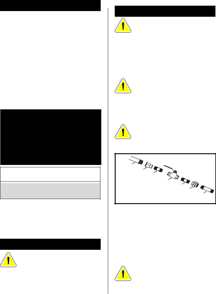
GAS LINE INSTALLATION
When purging gas line, the front glass must be removed.
The gas pipeline can be brought in through the rear of the fireplace as well as the bottom. Knockouts are provided on the bottom behind the valve to allow for the gas pipe installation and testing of any gas connection. It is most convenient to bring the gas line in from the rear right side of the valve, as this allows fan installation or removal without disconnecting the gas line.
The gas line connection can be made with properly tinned 3/8" copper tubing, 3/8" rigid pipe or an approved flex connector. Since some municipalities have some additional local codes, it is always best to consult your local authority and the CAN/CGAB149 (.1 or
.2) installation code.
FOR U.S.A Installations consult the current National Fuel Gas Code, ANSI Z223.1
Always check for gas leaks with a mild soap and water solution. Do not use an open flame for leak testing.
The gas control is equipped with a captured screw type pressure test point, therefore it is not necessary to provide a 1/8" test point up stream of the control.
1/2" GAS SUPPLY
1/2" X 3/8" REDUCER
3/8" NIPPLE
3/8" X 3/8" SHUT OFF VALVE
3/8" NIPPLE
3/8" UNION
3/8" NIPPLE
Fig. 2 Typical gas supply installation
When using copper or flex connector use only approved fittings. Always provide a union when using black iron pipe so that gas line can be easily disconnected for burner or fan servicing. See Fig. 2. See gas specification for pressure details and ratings.
The fireplace valve must not be subjected to any test pressures exceeding 1/2 psi. Isolate or disconnect this or any other gas appliance control from the gas line when pressure testing.
DO NOT USE THIS FIREPLACE IF ANY PART OF THIS FIREPLACE HAS BEEN UNDER WATER. IMMEDIATELY CALL A QUALIFIED SERVICE TECHNICIAN TO INSPECT THE HEATER AND TO REPLACE ANY PART CONTROL WHICH HAS BEEN UNDER WATER.

|
|
|
Manifold Gas Outlet |
|
Brass |
|
|
Brass Plug |
|
Plug |
|
|
|
|
Thermostat |
|
|
|
Pressure |
Bulb |
|
|
|
|
|
|
|
Regulator |
|
|
|
|
|
|
Gas Inlet |
|
|
|
|
Thermocouple |
|
|
|
|
Inlet |
|
|
|
|
Pilot Tube entry |
|
|
|
|
|
|
|
|
Control |
Pilot Adjustment |
|
|
Control |
Knob |
Screw |
|
|
Knob |
|
|
|
|
HI |
|
|
|
it |
OFF |
|
|
LO |
|
PILOT |
|
|
|
|
|
|
|
Minimum |
Fig. 3 |
||
|
Rate Screw |
|||
|
|
|||
(Non-Adjustable) |
|
|||
On fireplaces equipped with Eurosit 630 gas valves there are brass plugs in two of the holes. These plugs are not to be removed. The gas inlet hole has a plastic cap in it. Remove the plastic cap and connect your gas supply line at this point. (Fig. 3).
INSTALLATION OF REMOTE
SWITCH FOR RN/RP GAS VALVE
Install on/off switch assembly on either the rear right or left side of the RFS22/RFS32/RFS42 Gas Fireplace.
1.Remove the screw at the back of the cabinet top either on the left or the right side of the fireplace.
2.Position switch assembly onto the back of the fireplace, then fasten two screws as shown in Fig. 5.
3.Attach wiring under the clips on the rear casing (Fig. 5) and install wiring through the rear opening of the fireplace before connecting to the valve as shown in Fig. 4.
VALVE |
|
|
|
|
TPTH |
|
|
TH |
|
THERMOPILE |
|
|
|
|
TP |
|
|
TP |
|
TH |
|
|
TP TH |
|
|
|
P |
PILOT |
|
|
I |
|
||
|
TOL |
|
ADJ |
|
|
|
|
||
ON/OFF SWITCH OR |
|
|
|
|
MILLIVOLT THERMOSTAT |
|
|
Fig. 4 |
|
|
|
|
||
|
Screw |
On/off switch |
(through existing hole) |
assembly |
Screw |
|
|
Clips |
|
|
Wiring for milli-volt |
|
gas valves |
Fig. 5
- 6 -
OPTIONAL FAN KIT - FK24
STANDARD WITH RFS42
It will be easier to install the fan before connecting the gas line to the fireplace.
1.Open front access door panel by pulling forward on brass lip.
2.Guide the fan through the opening at the back of the pedestal, with the outlet pointed up and the fan mounting bracket facing the back of the fireplace. The fan mounts over two studs which hold the fan just below the firebox floor. Do not install this fan on the base. Hold the fan in place with the two nuts provided. (Fig. 7)
3.Locate the fan speed control/junction box on screw studs provided on base of the fireplace. Tighten with 3/8" nuts provided.
4.Install thermal sensor element on screw studs located to the right of the gas valve on the burner base.
5.Plug in grounded service cord to a convenient wall receptacle.
THIS FAN ASSEMBLY COMES COMPLETELY WIRED TO ELIMINATE THE NEED FOR ELECTRICIANS. THIS
ELECTRICAL DEVICE, WHEN INSTALLED, MUST BE ELECTRICALLY CONNECTED AND GROUNDED IN ACCORDANCE WITH LOCAL CODES. IN THE ABSENCE
OF LOCAL CODES, WITH THE CURRENT CSA C22.1 CANADIAN ELECTRICAL CODE.
FOR U.S.A. INSTALLATION: FOLLOW LOCAL CODES AND THE NATIONAL ELECTRICAL CODE ANSI/NFPA
NO.70-1984.
Should this fan require servicing, the power supply must be disconnected. For rewiring of any replacement components see Fig. 6.
A = Speed Control |
C |
|
B = Temperature Sensor |
B |
|
C = Fan |
||
|
||
|
A |
|
BLACK |
|
|
WHITE |
|
|
GROUND |
Fig. 6 |
Thermal sensor location
Valve
Stud
Fan is installed at the back of the pedestal


 Fan speed control/ Junction box
Fig. 7
TOP VIEW
 Loading...