


INSTALLER/CONSUMER SAFETY INFORMATION
PLEASE READ THIS MANUAL BEFORE INSTALLING AND USING APPLIANCE
WARNING!
IF THE INFORMATION IN THIS MANUAL IS NOT FOLLOWED EXACTLY, A FIRE OR EXPLOSION MAY RESULT CAUSING PROPERTY DAMAGE, PERSONAL INJURY OR LOSS OF LIFE.
FOR YOUR SAFETY
Installation and service must be performed by a qualified installer, service agency or the gas supplier.
WHAT TO DO IF YOU SMELL GAS:
•Do not try to light any appliance.
•Do not touch any electric switch;
•Do not use any phone in your building.
•Immediately call your gas supplier from your neighborʼs phone. Follow the gas suppliers instructions.
•If you cannot reach your gas supplier call the fire department.
DO NOT STORE OR USE GASOLINE OR OTHER FLAMMABLE VAPORS AND LIQUIDS IN THE VICINITY OF THIS OR ANY OTHER APPLIANCE.
Chateau™
Direct Vent Decorative
Gas Appliance
Model: DVT38, DVT44
|
S |
IG |
|
E |
N |
||
D |
|
|
|
CERTIFIED
C |
D |
E |
|
|
RTIFIE |
Installation Instructions and
Homeownerʼs Manual
CFM Specialty Home Products
410 Admiral Blvd. • Mississauga, Ontario, Canada L5T 2N6 • 905-670-7777 www.majesticproducts.com • www.vermontcastings.com
INSTALLER: DO NOT DISCARD THIS MANUAL - LEAVE FOR HOMEOWNER
20006081 3/05 Rev. 7

Chateau™
Table of Contents
Please read the installation & operating instructions before using this appliance.
Thank you and congratulations on your purchase of a Vermont Castings, Majestic Products fireplace. IMPORTANT: Read all instructions and warnings carefully before starting installation.
Failure to follow these instructions may result in a possible fire hazard and will void the warranty.
Installation & Operating Instructions |
|
Important Curing/Burning Instructions................................................................................. |
3 |
Locating Your Fireplace....................................................................................................... |
3 |
Fireplace Dimensions.......................................................................................................... |
4 |
Clearance to Combustibles ................................................................................................. |
5 |
Mantels ............................................................................................................................... |
5 |
Hearth ............................................................................................................................... |
5 |
Framing & Finishing ............................................................................................................ |
6 |
Final Finishing ..................................................................................................................... |
7 |
Gas Specifications............................................................................................................... |
7 |
Gas Inlet and Manifold Pressures ....................................................................................... |
7 |
High Elevations ................................................................................................................... |
7 |
Gas Line Installation............................................................................................................ |
7 |
Remote ON/OFF Switch...................................................................................................... |
8 |
Electrical Junction Box ........................................................................................................ |
8 |
Electronic Gas Control Valve............................................................................................... |
8 |
General Venting Information |
|
General Venting................................................................................................................... |
9 |
General Venting Information - Termination Location ......................................................... |
10 |
General Information Assembling Vent Pipes..................................................................... |
11 |
SK8 Venting Pipes............................................................................................................. |
11 |
Horizontal Termination....................................................................................................... |
12 |
Vertical Termination........................................................................................................... |
12 |
Sidewall Applications......................................................................................................... |
12 |
Use of the Restrictor Plates in Horizontal Venting Applications ........................................ |
12 |
Sidewall Installation........................................................................................................... |
14 |
Vertical Through-the-Roof Applications............................................................................. |
15 |
Use of Restrictor Plates for Vertical Venting Applications ................................................. |
15 |
Vertical Through-the-Roof Installation............................................................................... |
17 |
Chimney Components....................................................................................................... |
19 |
Operating Instructions |
|
Glass Information .............................................................................................................. |
20 |
Window Frame Assembly Removal................................................................................... |
20 |
Glass Cleaning.................................................................................................................. |
20 |
Restrictor Plate Installation................................................................................................ |
20 |
Ceramic Refractory Installation ......................................................................................... |
21 |
Log, Lava Rock and Ember Placement............................................................................. |
22 |
Flame & Temperature Adjustment..................................................................................... |
24 |
Flame Characteristics........................................................................................................ |
24 |
Lighting and Operating Instructions (Standing Pilot Models) ............................................ |
25 |
Lighting and Operating Instructions (Electronic Ignition Models) ...................................... |
26 |
Troubleshooting................................................................................................................. |
27 |
Fuel Conversion ................................................................................................................ |
29 |
Maintenance |
|
Cleaning the Standing Pilot Control System ..................................................................... |
32 |
Cleaning Electronic Ignition System.................................................................................. |
32 |
Battery Replacement for Ignitor Module............................................................................ |
32 |
Replacement Parts ..................................................................................................................... |
33 |
Optional Accessories .................................................................................................................. |
36 |
Warranty ....................................................................................................................................... |
37 |
2 |
20006081 |
Chateau™
Installation & Operating Instructions
This gas fireplace should be installed by a qualified installer in accordance with local building codes and with current CSAB149.1 Installation codes for Gas Burning Appliances and Equipment. For USA Installations follow local codes and/or the current National Fuel Gas Code. ANSI Z223.1/NFPA 54.
FOR SAFE INSTALLATION AND OPERATION PLEASE NOTE THE FOLLOWING:
1 . This fireplace gives off high temperatures and should be located out of high traffic areas and away from furniture and draperies.
2.Children and adults should be alerted to the hazards of the high surface temperatures of this fireplace and should stay away to avoid burns or ignition of clothing.
3.CAUTION: Due to high glass surface temperature children should be carefully supervised when in the same room as fireplace.
4.Under no circumstances should this fireplace be modified. Parts removed for servicing should be replaced prior to operating this fireplace again.
5.Installation and any repairs to this fireplace must be performed by a qualified installer, service agency or gas supplier. A professional service person should be contacted to inspect the fireplace annually. More frequent cleaning may be required due to excess lint and dust from carpeting, bedding material, etc.
6.Control compartments, burners and air passages in this fireplace should be kept clean and free of dust and lint. Make sure that the gas valve and pilot light are turned off before you attempt to clean this fireplace.
7.The venting system (chimney) of this fireplace should be checked at least once a year and if needed your venting system should be cleaned.
8.Keep the area around your fireplace clear of combustible materials, gasoline and other flammable vapor and liquids. This fireplace should not be used as a drying rack for clothing, nor should Christmas stockings or decorations be hung on or around the fireplace.
9.Under no circumstances should any solid fuels (wood, coal, paper or cardboard etc.) be used in this fireplace.
10.The flow of combustion and ventilation air must not be obstructed in any way.
11.When the fireplace is installed directly on carpeting, vinyl tile or any combustible material other than wood, this fireplace must be installed on a metal or wood panel extending the full width and depth of the fireplace.
12.This fireplace requires adequate ventilation and combustion air to operate properly.
13.This fireplace must not be connected to a chimney flue serving a separate solid fuel burning fireplace.
14.When the fireplace is not in use it is recommended that the gas control valve be left in the “OFF” position.
NOTE: This appliance uses a fast acting thermocouple and must be replaced with same.
Proposition 65 Warning: Fuels used in gas, woodburning or oil fired appliances, and the products of combustion of such fuels, contain chemicals known to the State of California to cause cancer, birth defects and other reproductive harm. California Health & Safety Code Sec. 25249.6
20006081
This appliance may be installed in an aftermarket permanently located, manufactured home or mobile home, where not prohibited by local codes.
This appliance is only for use with the type of gas indicated on the rating plate. This appliance is not convertibleforusewithothergases,unlessacertified kit is used.
The DVT38/44 has been approved for mobile home installations.
IMPORTANT:
PLEASE REVIEW THE FOLLOWING CAREFULLY
Remove any plastic from parts before turning the fireplace ON.
It is normal for fireplaces fabricated of steel to give off some expansion and/or contraction noises during the start up or cool down cycle. Similar noises are found with your furnace heat exchanger or car engine.
It is not unusual for your Vermont Castings, Majestic Products gas fireplace to give off some odor the first time it is burned. This is due to the curing of the paint and any undetected oil from the manufacturing process.
Please ensure that your room is well ventilatedopen all windows.
It is recommended that you burn your fireplace for at least ten (10) hours the first time you use it.
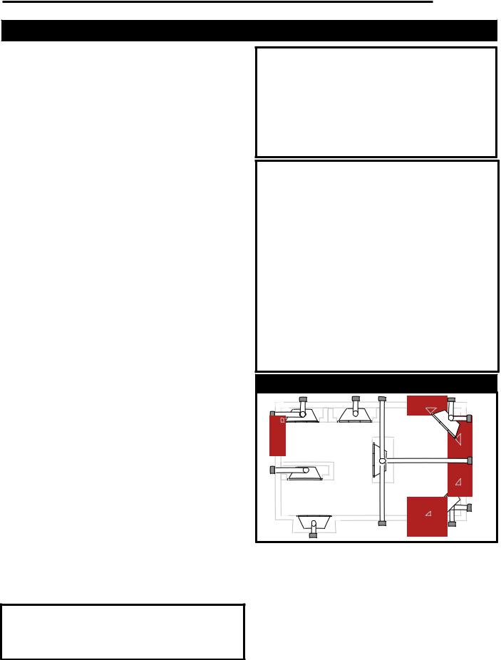
Locating Your Fireplace
E |
A |
B |
Y |
|
|
|
|
|
|
C |
X |
|
|
|
D |
|
|
Y |
|
B |
|
|
|
|
F |
|
|
|
LU584-1 |
Fig. 1 Locate gas fireplace. |
|
|
A) Flat on wall |
B) Cross corner |
C) **Island |
D) *Room divider |
E) *Flat on wall corner |
F) Chase installation |
Y) 6” minimum |
|
|
Note (Fig. 1): |
|
|
** Island (C) and Room Divider (D) installation is possible as |
||
long as the horizontal portion of the vent system (X) does not exceed 20ʼ (6 m). See details in Venting Section.
* When you install your Vermont Castings, Majestic Products fireplace in (D) Room divider or (E) Flat on wall corner positions (Y), a minimum of 6” (152 mm) clearance must be maintained
from the perpendicular wall and the front side edge of the fire- |
|
place. |
3 |
|

Chateau™
54" (1372mm)
Fireplace Dimensions - DVT38
|
Rough |
11 " |
17" (432mm) |
|
Opening |
(298mm) |
|
54" (1372mm) |
Depth |
|
|
3" (76mm)
25 " (648mm)
38
|
(968mm) |
|
|
(19mm) |
|
" |
|
|
|
|
|
|
|
|
|
3/4" |
|
|
|
(76mm) |
(1940mm) |
||
|
|
|
" |
|
|
|
3" |
76 |
|
|
|
28 " (724mm)
|
Rough Opening Width " |
Rough |
(1114mm) |
Opening |
|
Height |
|
49 " |
1 " |
(41mm) |
|
(1257mm) |
|
8 " Dia. (213mm)
11" Dia. (279mm)
3/4" (19mm) |
5 " |
|
(140mm) |
12 " (311mm)
33 " |
|
|
9 " |
|
(848mm) |
" (876mm) |
55" |
(235mm) |
|
29 " |
(1397mm) |
|
|
|
(746mm) |
|
|
7 " |
3 " |
|
|
|
(86mm) |
|
|
1/2" (13mm) |
|
(187mm) |
|
|
|
|
||
|
|
|
|
|
2 " |
37 " (962mm) |
|
|
10" |
(60mm) |
|
|
|
No drywall in this area, MUST use noncombustible wallboard such as Dura Rock.
(254mm)
 Valve box should not be left attached to the unit.
Fig. 2 Fireplace specifications and framing dimensions for DVT38.
Fireplace Dimensions - DVT44
57 " (1464mm)
|
Rough |
11 " |
|
|
(298mm) |
|
|
|
Opening |
|
23 " (587mm) |
57 " (1464mm) |
Depth |
|
|
3" (76mm)
25 " (648mm)
41
|
(1045mm) |
|
|
(19mm) |
|
" |
|
|
|
3/4" |
|
|
|
|
|
|
|
|
|
(76mm) |
(2067mm) |
||
|
|
|
" |
|
|
|
3" |
81 |
|
|
|
|
|
|
|
||
|
|
|
|
|
|
28 " (724mm)
|
Rough Opening Width " |
Rough |
(1267mm) |
Opening |
|
Height |
|
54 " |
1 " |
(41mm) |
|
(1394mm) |
|
8 " Dia. (213mm)
11" Dia. (279mm)
 3/4" (19mm)
  5 " (140mm)
12 " (311mm)
38 " |
|
|
9 " |
|
|
|
(978 mm) |
40 " (1029 mm) |
55" |
(235mm) |
|
|
|
34 " |
(1397mm) |
|
|
|
|
|
(875mm) |
|
|
|
7 " |
|
3 " |
|
|
|
|
|
(86mm) |
|
|
1/2" (13mm) |
|
|
(187mm) |
||
|
|
|
|
|||
|
|
|
|
|
|
|
2 " |
43 " (1114mm) |
|
|
|
|
10" |
(60mm) |
|
|
|
|
|
|
|
|
|
|
(254mm) |
||
No drywall in this area, MUST use noncombustible |
|
|||||
|
|
|
||||
wallboard such as Dura Rock. |
|
|
|
|
|
|
 Valve box should not be left attached to the unit.
4Fig. 3 Fireplace specifications and framing dimensions for the DVT44. |
20006081 |
Chateau™
|
Clearance to Combustibles |
|
|
|
|
|
|
|
|
|
|
|
|
|
|
|
|
|
|
|
|
|
|
|
|
|
|
|
|
|
|
|
|
|
|
|
|
|
|
|
|
|
|
|
|
|
|
|
|
|
|
|
|
|
|
|
|
|
|
|
|
|
|
|
|
|
|
|
|
|
|
|
|
|
|
|
|
||
|
|
|
|
|
|
|
|
|
|
|
|
|
|
|
|
|
|
|
|
|
|
|
|
|
|
|
|
|
|
|
|
|
|
|
|
|
|
||
|
Appliance |
|
|
|
|
|
|
|
|
|
|
|
|
|
|
|
|
|
|
|
|
|
|
|
|
|
|
|
|
|
|
|
|
|
|
|
|
|
|
|
Top Standoffs ............................................. |
0” (0mm) |
|
|
|
|
|
|
|
|
|
|
|
|
|
|
|
|
|
|
|
|
|
|
|
|
|
|
|
|
|
|
|
|
|
|
|
|
|
|
Bottom........................................................ |
0” (0mm) |
|
|
|
|
|
|
|
|
|
|
|
|
|
|
|
|
|
|
|
|
|
|
|
|
|
|
|
|
|
|
|
|
|
|
|
|
|
|
Side Standoffs............................................ |
0” (0mm) |
|
|
|
|
|
|
|
|
|
|
|
|
|
|
|
|
|
|
|
|
|
|
|
|
|
|
|
|
|
|
|
|
|
|
|
|
|
|
...........................................Back Standoffs |
0” (0mm) |
|
|
|
|
|
|
|
|
|
|
|
|
|
|
|
|
|
|
|
|
|
|
|
|
|
|
|
|
|
|
|
|
|
|
|
|
|
Venting |
|
|
|
|
|
|
|
|
|
|
|
|
|
|
|
|
|
|
|
|
|
|
|
|
|
|
|
|
|
|
|
|
|
|
|
|
|
|
|
|
Horizontal Termination through-a-side wall: |
|
|
|
|
|
|
|
|
|
|
|
|
|
|
|
|
|
|
|
|
|
|
|
|
|
|
|
|
|
|
|
|
|
|
|
|
|
|
|
|
|
|
|
|
|
|
|
|
|
|
|
|
|
|
|
|
|
|
|
|
|
|
|
|
|
|
|
|
|
|
|
|
|
|
|
|
||
|
|
|
|
|
|
|
|
|
|
|
|
|
|
|
|
|
|
|
|
|
|
J I |
|
|
|
H |
|
|
|
|
|
|
|
||||||
|
Vertical Sections: |
|
|
|
|
|
|
|
|
|
|
|
|
|
|
|
|
|
|
|
|
|
|
|
|
|
|
|
|
|
G |
|
|
|
|||||
|
|
|
|
|
|
|
|
|
|
|
|
|
Mantel |
|
|
|
|
|
|
|
|
|
|
|
|
|
|
|
|
||||||||||
|
|
|
|
|
|
|
|
|
|
|
|
|
|
|
|
|
|
|
|
|
|
|
|
|
|
|
|
|
|||||||||||
|
|
|
|
|
|
|
|
|
|
|
|
|
|
|
|
|
|
|
|
|
|
|
|
|
|
|
|
|
|||||||||||
|
...............................................Sides |
2¹⁄ ” (64mm) |
|
|
|
|
|
|
|
|
|
|
|
|
|
|
|
|
|
|
|
|
|
|
|
|
|
|
|
|
|
||||||||
|
|
|
|
|
|
|
|
|
|
|
|
|
|
|
|
|
|
|
|
|
|
|
|
|
|
|
|
|
|
|
|
|
|
F |
|
|
|||
|
|
|
|
|
|
|
|
|
|
|
|
Leg |
|
|
|
|
|
|
|
|
|
|
|
|
|
|
|||||||||||||
|
Horizontal Sections: |
|
|
|
|
|
|
|
|
|
|
|
|
|
|
|
|
|
|
|
|
|
|
|
|
|
|
|
|
||||||||||
|
|
|
|
|
|
|
|
|
|
|
|
|
|
|
|
|
|
|
|
|
|
|
|
|
|
|
|
|
|
|
|
|
|
|
|
|
|
|
|
|
|
|
|
|
|
|
|
|
|
|
|
|
|
|
|
|
|
|
|
|
|
|
|
|
|
|
|
|
|
|
|
|
|
|
|
|
|
|
|
|
Top.................................................. |
3¹⁄ ” (89mm) |
|
|
CFM164b |
|
|
|
|
|
|
|
|
|
|
|
|
|
|
|
|
||||||||||||||||||
|
|
|
|
|
|
|
|
|
|
|
|
|
|
|
|
|
|||||||||||||||||||||||
|
Bottom |
1¹⁄ ” (38mm) |
|
|
|
|
|
|
|
|
|
|
|
|
|
|
|
|
|
|
|
|
|
|
|
|
|
|
|
|
|
|
|
|
|
|
|
|
|
|
|
|
|
|
|
|
|
|
|
|
|
|
|
|
|
|
|
|
|
|
|
|
|
|
|
|
|
LK |
|
|
|
|
|
|
|
|
|||
|
Sides............................................... |
2¹⁄ ” (64mm) |
|
|
|
|
|
|
|
|
|
|
|
|
|
|
|
|
|
|
|
|
|
|
|
|
|
|
|
|
|
|
|
|
|
|
|
||
|
|
|
|
|
|
|
|
|
|
|
|
|
|
|
|
|
|
|
|
|
|
|
|
|
M |
|
|
|
|
|
|
|
|
|
|||||
|
Vertical Vent Application: |
|
|
|
|
|
|
|
|
|
|
|
|
|
|
|
|
|
|
|
|
|
|
|
|
|
|
|
|
|
|
|
|
|
|
|
|
||
|
|
|
|
|
|
|
Side of Fireplace |
|
|
N |
|
|
|
|
|
|
|
|
|
||||||||||||||||||||
|
|
|
|
|
|
|
|
|
|
|
|
|
|
|
|
|
|||||||||||||||||||||||
|
Sides .............................................. |
1¹⁄ ” (38mm) |
|
|
|
|
|
|
O |
|
|
|
|
|
|
|
|
|
|
|
|
|
|||||||||||||||||
|
|
|
|
|
|
|
|
|
|
|
|
|
|
|
|
|
|
|
|
|
|
|
|
|
|
|
|
|
|
|
|
|
|
|
|
|
|
||
Mantels
The height that a combustible mantel is fitted above the fireplace is dependent on the depth of the mantel. This
also applies to the distance between the mantel leg (if
fitted) and the fireplace. Noncombustible Finish Material
For the correct mounting height and widths refer to Figs. 4a and 4b, the following Mantel Charts.
Noncombustible mantels and legs may be installed at any height and width around the appliance.
When using paint or lacquer to finish the mantel, such |
|
|
|
|
|
|
|
|
CFM170a |
|||||||||||||||||||||||||
|
|
|
|
|
|
|
|
|
||||||||||||||||||||||||||
paint or lacquer must be heat resistant to prevent |
|
|
|
Mantel |
|
|
Mantel Leg from Side |
|||||||||||||||||||||||||||
discoloration. |
|
|
|
|
|
|
|
|
|
|
|
|
|
|
|
|
|
|
Ref. |
|
Leg Depth |
Ref. |
|
of Comb. Opening |
||||||||||
|
|
|
|
|
|
|
|
|
|
|
|
|
|
|
|
|
|
|
|
|
|
|
|
|
|
|
F |
|
12” (305mm) |
K |
|
12” (305mm) |
||
|
|
|
|
|
|
|
|
|
|
|
|
|
|
|
|
|
Combustible |
|
||||||||||||||||
|
|
|
|
|
|
|
|
|
|
|
|
|
|
|
|
|
|
G |
|
9” (229mm) |
L |
|
9” (229mm) |
|||||||||||
|
|
|
|
|
|
|
|
|
|
|
|
|
|
|
|
|
Framing and Fin- |
|
|
|
||||||||||||||
|
|
|
|
|
|
|
V |
|
|
|
|
|
|
|
|
ish Wall Above |
|
H |
|
6” (152mm) |
M |
|
6” (152mm) |
|||||||||||
|
|
|
|
|
|
|
|
|
|
|
|
|
|
|
Standoffs |
|
I |
|
4” (102mm) |
N |
|
4” (102mm) |
||||||||||||
|
|
|
|
|
|
|
|
|
|
|
|
|
|
|
|
|
|
|
|
|||||||||||||||
|
|
|
|
|
|
|
W |
|
|
|
|
|
|
|
|
May use combus- |
|
|
|
|
|
|
|
|
|
|||||||||
|
|
|
|
|
|
|
|
|
|
|
|
|
|
|
|
J |
|
3” (76mm) |
O |
|
3” (76mm) |
|||||||||||||
|
|
|
|
|
|
|
|
|
|
|
|
|
|
|
tible facing mate- |
|
|
|
||||||||||||||||
|
|
|
|
|
|
|
X |
|
|
|
|
|
|
|
|
rial in this area |
Fig. 4b |
Combustible mantel leg minimum installation. |
||||||||||||||||
|
|
|
|
|
|
|
|
|
|
|||||||||||||||||||||||||
|
|
|
|
|
|
|
Y |
|
|
|
|
|
|
|
|
Standoff |
|
|
|
|
|
|
|
|
|
|||||||||
|
|
|
|
|
|
|
|
|
|
|
|
|
|
|
|
|
|
|
|
|
|
|
|
|
|
|
|
Hearth |
|
|
|
|||
|
|
|
|
|
|
|
Z |
|
|
|
|
|
|
|
|
|
|
|
|
|
|
|
|
|
|
|
|
|
|
|
|
|||
|
|
|
|
|
|
|
|
|
|
|
|
|
|
|
|
|
|
|
|
|
|
|
|
|
|
|
|
|
|
|
|
|
||
|
|
A |
|
B |
C |
|
|
|
|
|
|
|
|
|
|
|
|
|
|
|
|
|
|
|
|
A hearth is not mandatory but is recommended for |
||||||||
|
|
|
D |
E |
|
|
|
|
|
|
|
|
|
|
|
|
|
|
|
|
|
aesthetic purposes. We recommend a noncombustible |
||||||||||||
|
|
|
|
|
|
|
|
|
|
|
|
|
|
|
|
|
|
|
|
|
|
|
|
|
|
hearth which projects out 12” (305mm) or more from |
||||||||
|
Noncombustible Finish |
|
|
|
|
|
|
|
|
|
|
|
|
|
|
|
|
|
||||||||||||||||
|
|
|
|
|
|
|
|
|
|
|
|
|
|
|
|
|
|
the front of the fireplace. The hearth cannot exceed 1¹⁄ ” |
||||||||||||||||
|
Material |
|
|
|
|
|
|
|
|
|
|
|
|
|
|
|
|
|
(38mm) in height from bottom of fireplace for ease of |
|||||||||||||||
|
(Such as Dura Rock) |
|
|
|
|
|
|
|
|
|
|
|
|
|
|
|
|
|
||||||||||||||||
CFM146c |
|
Fireplace Front |
|
|
|
|
|
|
|
|
Top of Sheet |
|
|
door accessibility. (Fig. 5) |
|
|
|
|||||||||||||||||
|
|
|
|
|
|
|
|
|
|
|
|
|
|
|||||||||||||||||||||
|
|
|
|
|
|
|
|
|
|
|
|
|
Metal |
|
|
Cold climate installation recommendation: |
||||||||||||||||||
|
|
|
|
|
|
|
|
|
|
|||||||||||||||||||||||||
|
|
|
|
|
|
Mantel Chart |
||||||||||||||||||||||||||||
|
|
|
|
|
|
|
|
When installing this unit against a non- |
||||||||||||||||||||||||||
|
|
|
Mantel Shelf |
|
|
|
|
Mantel from Top |
|
|
insulated exterior wall or chase, it is |
|||||||||||||||||||||||
|
Ref. |
or Breast Plate |
Ref. |
|
of Comb. Chamber |
|
|
|||||||||||||||||||||||||||
|
|
|
|
mandatory the outer walls be insulated to |
||||||||||||||||||||||||||||||
|
|
|
|
Depth |
|
|
|
|
|
|
|
|
|
|
|
|
|
|
|
|
|
|
|
|||||||||||
|
|
|
|
|
|
|
|
|
|
|
|
|
|
|
|
|
|
|
|
|
|
|
conform to applicable insulation codes. |
|||||||||||
|
V |
|
10” (254 mm) |
A |
|
|
|
|
|
10” (254 mm) |
|
|
||||||||||||||||||||||
|
|
|
|
|
|
|
|
|
|
|
|
|
|
|
|
|||||||||||||||||||
|
W |
|
9” (229 mm) |
B |
|
|
|
|
|
9” (229 mm) |
|
|
|
|
|
|
|
|
|
|||||||||||||||
|
X |
|
8” (203 mm) |
C |
|
|
|
|
|
8” (203 mm) |
|
|
|
|
|
|
|
|
|
|||||||||||||||
|
Y |
|
7” (178 mm) |
D |
|
|
|
|
|
7” (178 mm) |
|
|
|
|
|
|
|
|
|
|||||||||||||||
|
Z |
|
6” (152 mm) |
E |
|
|
|
|
|
6” (152 mm) |
|
|
|
|
|
|
|
|
|
|||||||||||||||
Fig. 4a Combustible mantel minimum installation.
20006081 |
5 |
Chateau™
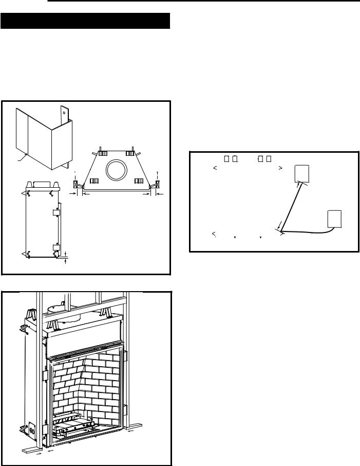
Framing and Finishing
NOTE: The valve box assembly must be installed in the same room as the fireplace.
1.Choose the unit location.
2.The unit is shipped with four (4) nailing flanges mounted to the sides near the front corners. (Fig. 5)
3.Frame the fireplace with a header across the top of the standoff. (Fig. 6) It is very important to allow for the finished wall face along with marble, tiles or any
Bend |
|
|
Line |
|
|
3" |
3" |
|
(76mm) Min. |
||
(76mm) Min. |
||
|
||
1¹⁄" |
|
|
(38mm) |
|
|
Max. Hearth Height |
FP1357 |
|
|
Fig. 5 Nailing flanges.

 3" (76mm)
3" |
FP1358 |
(76mm) |
Fig. 6 Fireplace framing.
other noncombustible face finish material desired when setting the depth of the framing.
4.Attach the fireplace nailing flanges to the frame as shown in Figure 5.
5.The gas components are located in the control panel assembly attached to the right side of the unit. Choose the desired location on the wall or mantel for the valve box assembly. The conduit length is 5ʼ (1524mm). (Fig. 7) The framing dimensions for the box are 12¹⁄”L x 9¹⁄”W x 5⁄”D (311mm x 235mm x 143mm). When the framing for the box is complete, remove the screws securing the valve box to the outer casing. Carefully remove the valve box and, without stressing the conduit, slide the box into the framed opening. Replace the screws removed from the side of the outer casing.
53" |
(1346mm) |
|
 45" (1143mm)

Fig. 7 Valve box assembly location.
6.To secure the valve box assembly to the framing members, open the box door, remove extension knob(s). For units with two piece cover plates, remove the front cover plate by removing the screws holding the front plate to the second plate. Disconnect the wires for the pilot indicator and remove the second plate located at the top of the box.
For units with a one piece cover plate, remove the valve cover by removing the two (2) screws securing the valve cover to the box, hold the cover plate with one hand and disconnect the wires to the switch and pilot indicator (R models only). NOTE: Do not allow the valve cover plate to hang from the pilot indicator wires as this could damage the wires.
Secure the box to the framing through the two (2) holes at the top and one (1) on each side using sheet rock screws. (Fig. 8) After framing the box, replace the wires, the valve cover, the extension knob(s) in reverse order.
NOTE: The pilot indicator body is labelled +/-, make sure the positive wire on the pilot indicator goes to ground and the negative goes to the plug between the valve and the thermocouple.
6 |
20006081 |
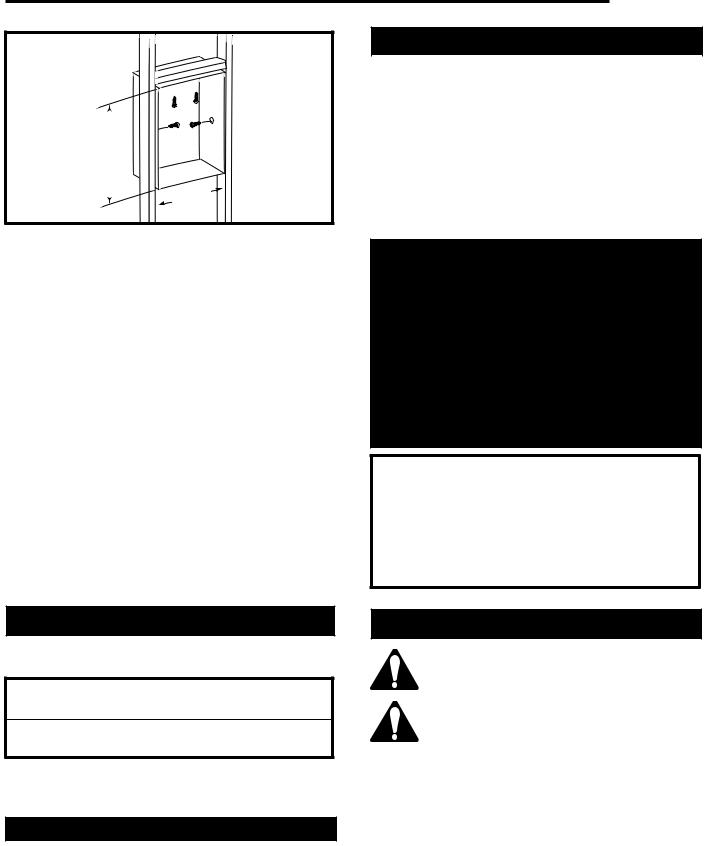
12 " (311mm)
9 " |
|
(235mm) |
FP1362 |
Fig. 8 Valve box framing.
7.The U-channel located on the top of the unit as well as the nailing flanges on the sides that were mentioned in Step 1, are designed to accommodate noncombustible board (recommended Dura-Rock). They are positioned 1” (25mm) back from the face of the unit. NOTE: The U-channel depth can be adjusted by loosening the hex nut inside the channel.
If marble, tile or any other noncombustible decorative face finish material is desired, a 3” (76mm) wide noncombustible board (recommended Dura-Rock) is to be nailed to the nailing flanges on both sides of the unit. Also, 12” (305mm) of noncombustible board is to be nailed to the front face of the U-chan- nel and the top framing member above the standoff.
Combustible material can then be brought to the outside edges of the noncombustible board installed earlier. Any noncombustible decorative face finish could be brought to the sides and top of the unit and can cover the framing and sheet rock. If a decorative facing is not desired, then the noncombustible boards must be double thickness and brought flush with the face of the unit.
Final Finishing
Noncombustible materials such as brick or tile may be brought to the edges of the face of the appliance.
DVT38 / DVT44
Certified To
ANSI Z21.50b-2002/CSA 2.22b-2002
Vented Gas Fireplace
DVT38 Units: GF1HC0, GF1IC0, GF1AC0, GF1BC0 DVT44 Units: E21H00, E21I00, E21A00, E21B00
Gas Inlet and Manifold Pressures
|
Natural |
LP (Propane) |
Minimum Inlet Pressure |
5.5” w.c. |
11.0” w.c. |
Maximum Inlet Pressure |
14.0” w.c. |
14.0” w.c. |
Manifold Pressure |
3.5” w.c. |
10.0” w.c. |
Chateau™
Gas Specifications
|
|
|
MAX. |
MIN. |
|
|
GAS |
INPUT |
INPUT |
MODEL |
FUEL |
CONTROL |
B.T.U.H |
B.T.U.H. |
DVT38RN |
Natural Gas |
Millivolt |
46,000 |
34,000 |
DVT38RP |
Propane |
Millivolt |
46,000 |
36,000 |
DVT38EN |
Natural Gas |
24V Hi/Lo |
46,000 |
34,000 |
DVT38EP |
Propane |
24V Hi/Lo |
46,000 |
36,000 |
DVT44RN |
Natural Gas |
Millivolt |
60,000 |
37,000 |
DVT44RP |
Propane |
Millivolt |
60,000 |
45,000 |
DVT44EN |
Natural Gas |
24V Hi/Lo |
60,000 |
37,000 |
DVT44EP |
Propane |
24V Hi/Lo |
60,000 |
45,000 |
High Elevations
Input ratings are shown in BTU per hour and are certified without deration for elevations up to 4,500 feet (1,370m) above sea level.
For elevations above 4,500 feet (1,370m) in USA, installations must be in accordance with the current ANSI Z223.1/NFPA 54 and/or local codes having jurisdiction.
In Canada, please consult provincial and/or local authorities having jurisdiction for installations at elevations above 4,500 feet (1,370m).
WARNING: Improper installation, adjustment, alteration, service or maintenance can cause injury or property damage. Refer to this manual for correct installation and operational procedures. For assistance or additional information consult a qualified installer, service agency, or the gas supplier.
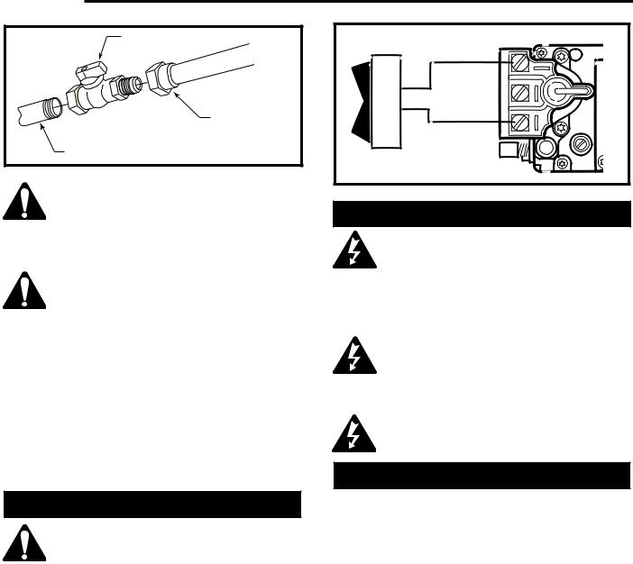
Gas Line Installation
When purging gas line the front glass must be removed.
A gas shut off valve must be installed on the gas pipe line going into the appliance
within easy access.
The gas pipeline can be brought in through the bottom right side of the valve box assembly.
The gas line connection can be made with properly tinned 1/2” copper tubing or 1/2” gas tight. Some municipalities have additional local codes, it is always best to consult your local authority and the CSA-B149.1 installation codes.
For USA installations consult the current National Fuel Gas Code, ANSI Z223.1/NFPA 54.
20006081 |
7 |
Chateau™ |
|
||
|
|
1/2” NPT X 1/2” Flare |
|
|
|
Shut-off Valve |
|
|
|
|
1/2” Gas Tight or |
|
|
|
Tinned Copper |
|
|
1/2” Gas Supply |
(from valve) |
FP297A |
(Not provided) |
||
|
|
||
Fig. 9 |
Typical gas supply installation. |
|
|
Always check for gas leaks with a mild soap and water solution applied with a
brush no larger than 1” (25mm). Never apply soap and water solution with a spray bottle. Do not use an open flame for leak testing.
The fireplace valve must not be subjected to any test pressures exceeding 1/2 psi.
Isolate or disconnect this or any other gas appliance control from the gas line when pressure testing.
The gas control is equipped with a captured screw type pressure test point, therefore it is not necessary to provide a 1/8” test point up stream of the control.
When using copper, use only approved fittings. Always provide a union when using black iron pipe so the gas line can be easily disconnected for burner servicing. A union may not be behind a wall. (Fig. 9) See the gas specifications for pressure details and ratings.
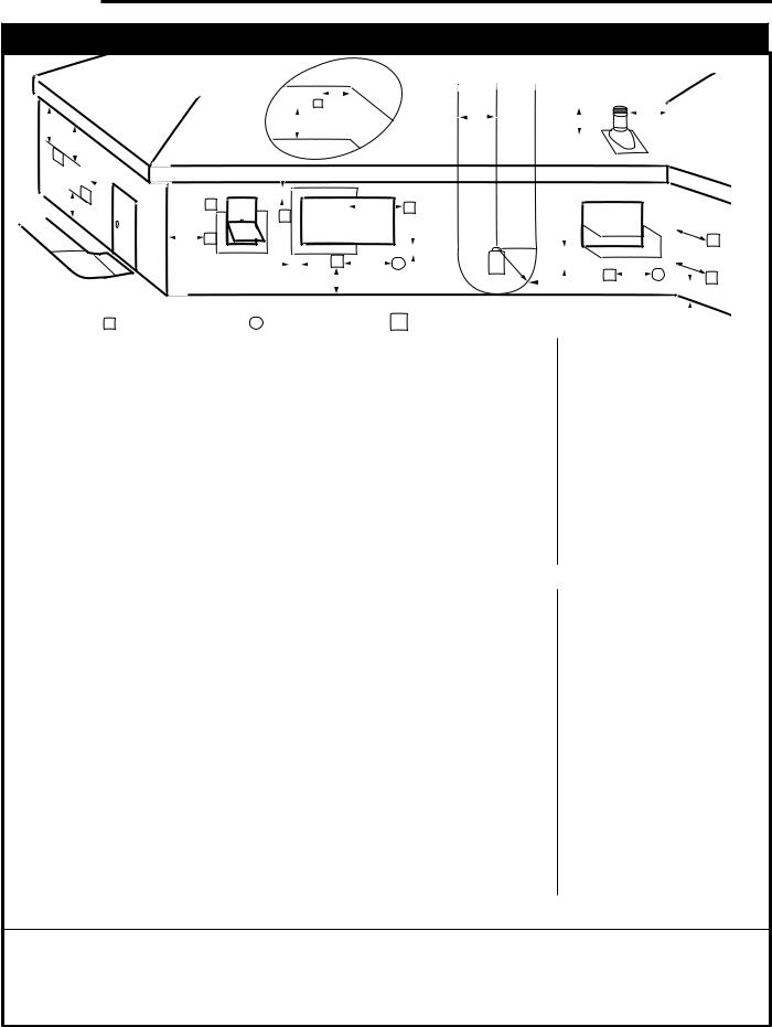
Remote ON/OFF Switch
Do not wire the remote ON/OFF wall switch for this gas appliance into a 120V power
supply.
The unit is equipped with an ON/OFF rocker switch at the valve box assembly. If a wall switch is desired, follow these instructions.
1.The valve box is equipped with two knockouts at the top right and left corners. The right knockout is designed to run the wall switch wires to the valve. Use Romex connectors when running wires through the valve box where the knockouts are located.
2.Attach the wire to the ON/OFF switch and install the switch into the receptacle box.
3.Connect the other end of the wire to the gas control valve. (Fig. 10)
8
Remote ON/OFF Switch
THTP |
|
|
|
|
TP |
|
|
|
|
TH |
|
|
|
|
|
|
|
|
|
|
|
|
|
|
|
|
|
||
|
|
|
|
|
|
|
|
||
Gas Control Valve |
|
|
|
|
|
|
|
FP1366 |
|
|
|
|
|
|
Fig. 10 Remote switch wiring diagram for R models.
Electrical Junction Box (E Units Only)
The fireplace, when installed, must be electrically connected and grounded in accordance with local codes or, in the absence of local codes, with the current CSA C22.1 Canadian Electrical Code or the national electrical code ANSI/NFPA No. 70 in the USA.
It is strongly suggested that the wiring of the Electrical Junction Box be carried out by a licensed electrician. The box should be near the valve box assembly to plug the cord into.
Ensure the power to the supply line has been disconnected before commencing this procedure.
Electronic Gas Control Valve
This appliance may be fitted with a Honeywell ignition module. The unit is shipped from the manufacturer with an ON/OFF switch. The ON/OFF switch is located in the valve box assembly. If desired a wall switch may be used.
Installation of the remote ON/OFF switch on electronic ignition units:
1.The valve box is equipped with two knockouts at the top right and left corners. The right knockout is designed to run the wall switch wires to the valve. The left knockout is designed for wiring the electronic unit (E model) to 120v with proper grounding. Use Romex connectors when running wires through the valve box where the knockouts are located.
2.Attach the wire to the ON/OFF switch and install the switch into the receptacle box. (Fig. 11)
3.Connect the White wire from the wall switch to the Black wire from the transformer, using an approved wire nut or terminal. Connect the Black wire from the wall switch to the Black wire running from the #6 position of the ignition module, also using an approved wire nut or terminal.
20006081

PILOT
|
|
HONEYWELL IGNITION MODULE |
|
|||
MV |
MV/VP PV |
24V |
24V |
SENSE SPARK |
||
GRD |
||||||
1 |
2 |
3 |
5 |
6 |
8 |
9 |
BLACK
WHITE
WHITE
|
LO |
|
|
|
HI |
|
|
To Receptacle |
|
|
|
Supplied |
|
|
|
in Valve Box |
|
|
|
|
NOVA SIT 822 VALVE |
BLACK |
|
120 VAC RTN |
24 VAC HOT |
BLACK |
|
|
|
||
WHITE |
BLACK |
|
|
|
WHITE |
WHITE |
|
BLACK |
|
||
GREEN |
|
WALL SWITCH |
|
|
|
||
120 VAC HOT |
24 VAC RET |
|
|
FP1367 |
40VA TRANSFORMER |
|
|
BLACK |
WHITE |
||
|
Fig. 11 Honeywell ignition module.
Chateau™
General Venting
Your fireplace is approved to be vented either through the side wall, or vertical through the roof.
•Only Vermont Castings, Majestic Products venting components specifically approved and labelled for this fireplace may be used.
•Venting terminals shall not be recessed into a wall or siding.
•Horizontal venting must be installed on a level plane without an inclining or declining slope.
There must not be any obstruction such as bushes, garden sheds, fences, decks or utility buildings within 24” (610mm) from the front of the termination hood.
Do not locate termination hood where excessive snow or ice build up may occur. Be sure to check vent termination area after snow falls, and clear to prevent accidental blockage of venting system. When using snow blowers, make sure snow is not directed towards vent termination area.
Location of Vent Termination
It is imperative the vent termination be located observing the minimum clearances as shown on following page.
20006081 |
9 |
Chateau™
General Venting Information - Termination Location
D
V
E
L
V
B
 C
C
V
F |
V |
|
|
 B
B
|
INSIDE |
|
|
|
|
|
|
|
CORNER DETAIL |
|
|
|
|
|
|
|
G |
|
|
|
|
|
|
|
V |
|
|
H |
|
N |
|
A |
|
|
|
N |
|
||
|
|
|
|
|
|||
|
|
|
|
|
|
||
B |
|
B |
V |
|
|
|
|
V |
|
|
|
|
|
||
|
|
|
|
|
|
G |
|
|
|
|
|
|
|
|
|
|
|
|
B |
|
|
|
V |
B |
V |
J X |
M |
|
|
G |
|
|
|
V K X |
|||||
|
A |
|
|
I |
|
V |
|
|
|
|
|
|
|
|
A |
|
|
V VENT TERMINATION X AIR SUPPLY INLET |
AREA WHERE TERMINAL IS NOT PERMITTED |
|||
|
CFM145a |
|
|
|
|
|
|
|
|
Canadian Installations1 |
US Installations2 |
|
|
|
A = |
Clearance above grade, veranda, porch, |
12” (30cm) |
|
12” (30cm) |
|
|
|
deck, or balcony |
|
|
|
|
|
B = Clearance to window or door that may be |
6” (15cm) for appliances |
6” (15cm) for appliances |
|||
|
|
opened |
< 10,000Btuh (3kW), 12” (30cm) |
< 10,000 Btuh (3kW), 9” |
||
|
|
|
for appliances > 10,000 Btuh (3kW) and |
(23cm) for appliances > 10,000 |
||
|
|
|
< 100,000 Btuh (30kW), 36” (91cm) |
Btuh (3kW) and < 50,000 Btuh |
||
|
|
|
for appliances > 100,000 Btuh (30kW) |
(15kW), 12” (30cm) for |
||
|
|
|
|
|
appliances > 50,000 Btuh (15kW) |
|
|
C = Clearance to permanently closed window |
12” (305mm) recommended to |
12” (305mm) recommended to |
|||
|
|
|
prevent window condensation |
prevent window condensation |
||
|
D = Vertical clearance to ventilated soffit located |
|
|
|
|
|
|
|
above the terminal within a horizontal |
18” (458mm) |
|
18” (458mm) |
|
|
|
distance of 2 feet (610mm) from the center |
*Clearances to soffit do not apply |
to “vinyl soffits”. |
||
|
|
line of the terminal |
||||
|
|
|
|
|
|
|
|
E = Clearance to unventilated soffit |
12” (305mm) |
|
12” (305mm) |
||
|
F = |
Clearance to outside corner |
see next page |
|
see next page |
|
|
G = Clearance to inside corner (see next page) |
see next page |
|
see next page |
||
|
H = Clearance to each inside of center line |
3ʼ (91cm) within a height of 15ʼ |
3ʼ (91cm) within a height of 15ʼ |
|||
|
|
extended above meter/regulator assembly |
above the meter/regulator assembly |
above the meter/regulator assy |
||
|
I = |
Clearance to service regulator vent outlet |
3ʼ (91cm) |
|
3ʼ (91cm) |
|
|
J = |
Clearance to nonmechanical air supply inlet |
6” (15cm) for appliances < 10,000 |
6” (15cm) for appliances |
||
|
|
to building or the combustion air inlet to any |
Btuh (3kW), 12” (30cm) for |
< 10,000 Btuh (3kW), 9” |
||
|
|
other appliances |
appliances > 10,000 Btuh (3kW) and < |
(23cm) for appliances > 10,000 |
||
|
|
|
100,000 Btuh (30kW), 36” (91cm) |
Btuh (3kW) and < 50,000 Btuh |
||
|
|
|
for appliances > 100,000 Btuh (30kW) |
(15kW), 12” (30cm) for |
||
|
|
|
|
|
appliances > 50,000 Btuh (15kW) |
|
|
K = |
Clearance to a mechanical air supply inlet |
6ʼ (1.83m) |
|
3ʼ (91cm) above if within 10ʼ |
|
|
|
|
|
|
(3m) horizontally |
|
|
L = |
Clearance above paved sidewalk or paved |
7ʼ (2.13m)† |
|
7ʼ (2.13m)† |
|
|
|
driveway located on public property |
|
|
|
|
|
M = Clearance under veranda, porch, deck or |
12” (30cm)‡ |
|
12” (30cm)‡ |
||
|
|
balcony |
|
|
|
|
N = Clearance above a roof shall extend a minimum of 24” (610mm) above the highest point when it passes through the roof surface, and any other obstruction within a horizontal distance of 18” (450mm).
1 In accordance with the current CSA-B149 Installation Codes
2 In accordance with the current ANSI Z223.1/NFPA 54 National Fuel Gas Codes
† A vent shall not terminate directly above a sidewalk or paved driveway which is located between two single family dwellings and serves both dwell ings
‡ only permitted if veranda, porch, deck or balcony is fully open on a minimum 2 sides beneath the floor: NOTE: 1. Local codes or regulations may require different clearances.
2. The special venting system used on CFM Specialty Home Products Direct Vent Fireplaces are certified as part of the appliance, with clearances tested and approved by the listing agency.
Fig. 12 Vent termination clearances.
Chateau™
Termination Clearances
Termination clearances for buildings with combustible and noncombustible exteriors.
Inside Corner |
|
Outside Corner |
|
|
|
A = |
|
|
B = |
A |
|
|
Combustible |
|
Combustible |
|
|
6"(152mm) |
|
|
6"(152mm) |
|
V |
Noncombustible |
|
Noncombustible |
2"(50mm) |
||
|
|
|||
V |
2"(50mm) |
|
B |
|
Balcony - |
|
Balcony - |
|
|
with no side wall |
|
with perpendicular side wall |
||
G |
H |
|
|
|
|
V |
|
V |
G = |
Combustible & |
J |
|
||
Noncombustible |
|
|
Combustible & |
|
|
Noncombustible |
H = 24"(610mm) |
|
12"(305mm) |
J = 20"(508mm) |
|
|
|
Recessed Location
 D
D 
C C
 E
E 
V
C = Maximum depth of 48" (1219mm) for recessed location.
D = Minimum width for back wall of a recessed location. Combustible 38"(965mm) Noncombustible 24"(610mm)
E = Clearance from corner in recessed location. Combustible 6"(152mm) Noncombustible 2"(50mm)
584-15
Fig. 13 Termination clearances.
Quick Reference for Fresh Air Restrictor Plate / Flue Baffle
Application |
Item |
DVT38N |
DVT38P |
DVT44N |
|
DVT44P |
|
||||||
SK8DVSK |
Flue Restrictor Plate |
3” |
None |
None |
|
4¹⁄ ” |
|
Fresh Air Restrictor Plate |
None |
None |
None |
|
#1 |
Vertical Less than 12’ |
Flue Restrictor Plate |
None |
None |
None |
|
None |
|
Fresh Air Restrictor Plate |
None |
None |
None |
|
None |
Vertical 12’ to 20’ |
Flue Restrictor Plate |
4¹⁄ ” |
4¹⁄ ” |
4¹⁄ ” |
|
4¹⁄ ” |
|
Fresh Air Restrictor Plate |
#3 |
#3 |
#3 |
|
#3 |
Vertical 20’ to 30’ |
Flue Restrictor Plate |
4¹⁄ ” |
4¹⁄ ” |
4¹⁄ ” |
|
4¹⁄ ” |
|
Fresh Air Restrictor Plate |
#2 |
#2 |
#2 |
|
#2 |
Vertical 30’ to 40’ |
Flue Restrictor Plate |
4¹⁄ ” |
4¹⁄ ” |
4¹⁄ ” |
|
4¹⁄ ” |
|
Fresh Air Restrictor Plate |
#1 |
#1 |
#1 |
|
#1 |
20006081 |
11 |
Chateau™
General Information Assembling Vent Pipes
SK8 Venting Pipes
Canadian Installations:
The venting system must be installed in accordance with the current CSA-B149 .1 installation code.
USA Installations:
The venting system must conform with local codes and/ or the current National Fuel Gas code ANSI Z223.1/ NFPA 54.
Only venting components manufactured by Vermont Castings, Majestic Products can be used in Direct Vent systems.
NOTE: The joints of the inner pipe (flue pipe) must be taped with 550°F or higher temperature metal adhesive tape that meets the requirements of F.A.R. 25.853(a)
High temperature sealant milpack or stove cement of 550°F or higher could be used instead. The joints of The outer pipe (fresh air pipe) must be taped with
315°F or higher temperature metal adhesive tape or the use of high temperature milpack or stove cement would be applicable. When using the unitized 30°, 45° or 90° elbows, apply 1/4” bead of high temperature, 550°F or higher, sealant (milpack or stove cement) to the joint of the inner pipe (flue pipe) and the straight section as it is impossible to be taped. The outer pipe must be taped with 315°F high temperature metal adhesive tape for proper sealing.
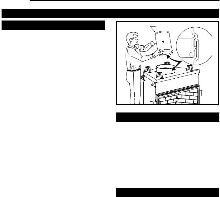
Start by attaching the first vent pipe section to the collar on top of the fireplace. In order to attach the first pipe section, it may be necessary to remove the top shield. Remove four (4) screws securing top shield, install first pipe section and replace top shield.
Install the pipe as shown in Figure 14. When you get a good lock, you will hear the pipe clearly snap together. Once sections are snap-locked in place, it is extremely difficult to get them apart. Make sure the pipe is firmly snapped and locked together as each pipe section is mounted.
When installing elbows, follow the same procedure. The joints of inner and outer elbow must be taped with UL approved high temperature metal adhesive tape for proper sealing. Be sure to always attach straps on upper elbow to a structural framing member.
For vertical installations, continue installing the pipe as required until pipe is installed up through the ceiling. At this point, you must install a firestop spacer.
Pipe Section
 UP
UP
Pipe
Rim
 Hem
Hem
 Lance
Lance
Pipe
Rim
FP1368
Fig. 14 Install pipe, listening for the snap-lock to fasten.
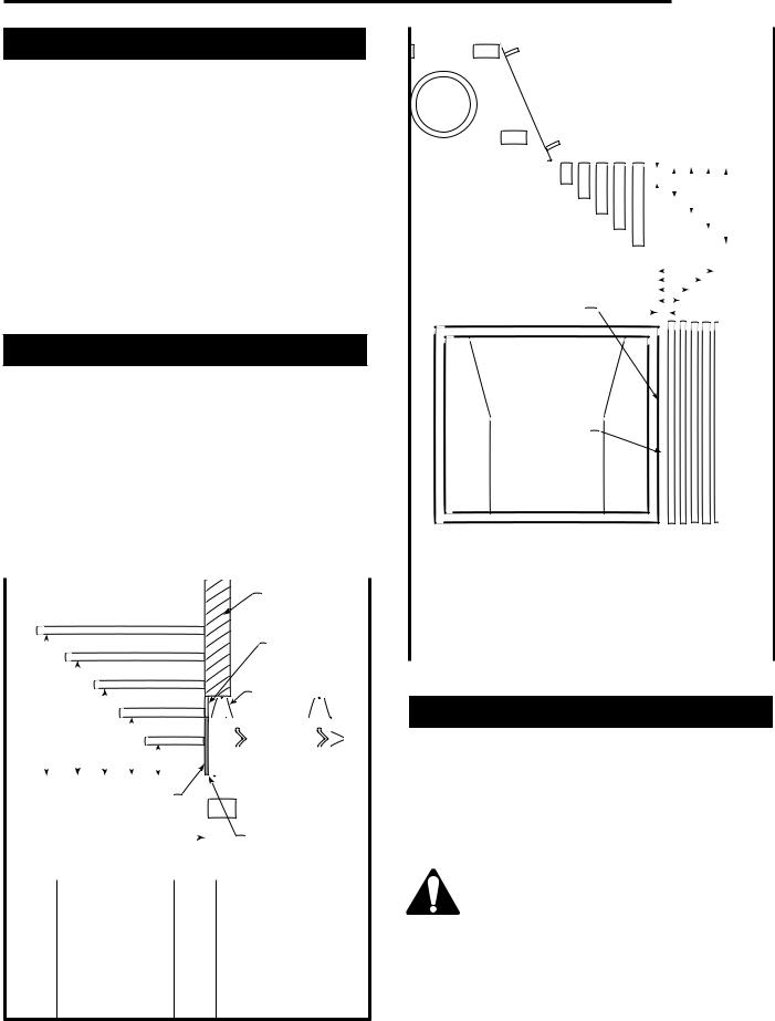
Horizontal Termination
The vent must rise vertically a minimum of 24” (610mm) off the top of the unit, before the first elbow. The horizontal run may extend up to 20ʼ (6m) and include a vertical rise of up to 40ʼ (12m). (Fig. 15) Horizontal termination must also meet the criteria shown in Figures 12 & 13.
•Approved vent systems must terminate above and including the heavy line in Figure 15.
•Two 45° elbows may be substituted for each single 90° elbow.
•With a rise between 2ʼ - 4ʼ, one (1) 90° or two (2) 45° elbows may be used.
Vertical Termination
A vertical vent system must terminate no less than 12ʼ (3.66m) and no more than 40ʼ (12m) above the appliance flue collar. A 2ʼ (610mm) vertical section must be installed before any offset. A maximum of 20ʼ (6.1m) horizontal and three (3) 90° elbows may be installed with a minimum of 12ʼ (3.66m) vertical section above the flue collar of the unit. Refer to Page 15, Figure 26 for more information.
A vertically terminated vent system must also conform to the following criteria:
•No more than three (3) 90° elbows may be used.
•Two (2) 45° elbows may be substituted for one (1) 90° elbow. No more than six (6) elbows may be used.
12 |
20006081 |
 Loading...