


MS 4150 RS
MP3
Owner’s manual and mounting instruction
Mode d’emploi et manuel d’installation
Bedienungsund Einbauanleitung
Gebruiksaanwijzing en inbouwhandleiding
Istruzioni d’uso e d’installazione
www.vdodayton.com
Italiano Nederlands Deutsch Français English
Attention!
Only use this system when it is safe to do so. It is more important to keep your eyes on the road and your hands on the wheel.
Due to constantly changing traffic conditions, we unfortunately cannot guarantee 100 % precision under all circumstances.
Attention !
N’utilisez le système que si vous ne mettez pas en danger votre vie ou celle des autres usagers de la route. Il est plus important de surveiller le trafic routier et d’avoir les mains sur le volant que de lire les informations apparaissant sur l’écran.
Étant donné que le sens de circulation a pu être changé entre temps, nous ne pouvons pas vous garantir une exactitude à 100 % des indications données.
Achtung!
Benutzen Sie das System nur, wenn die Sicherheit es zuläßt. Es ist wichtiger, auf den Verkehr zu achten und die Hände am Lenkrad zu lassen.
Aufgrund sich ständig ändernder Verkehrsführungen kann leider keine 100 %ige Genauigkeit unter allen Umständen gewährleistet werden.
Belangrijk!
Gebruik het systeem uitsluitend, als de veiligheid het toelaat. Het is belangrijker om op het verkeer te letten en de handen aan het stuur te houden.
Op grond van voortdurend veranderende verkeerssituaties kan helaas geen 100 % nauwkeurigheid onder alle omstandigheden worden gegarandeerd.
Attenzione!
Usare questo sistema solo se il traffico lo ammette. E´ importante tenere d´occhio la strada e le mani sul volante.
A causa dei cambiamenti continui della viabilità non si può garantire una precisione assoluta in tutte le circostanze.

|
SDVC |
|
|
|
|
B |
|
|
[A1] |
|
A |
|
|
|
|
|
[A3] |
|
|
|
|
||
|
|
|
|
|
|
||
|
[A2] |
|
|
|
|
|
|
[A5] |
[A4] |
[A6] |
[A8] |
[A7] |
|
|
|
|
|
|
|
+12V |
|
|
|
|
|
|
|
RR |
FR |
FL |
RL |
Power Amplifier |
Tel. in |
TMC receiver |
Remote |
CD Changer |
|
|
J |
|
|
|
|
|
|
B' |
|
|
|
|
F |
|
|
|
|
A' |
|
E |
|
|
|
|
|
|
B |
F |
|
|
|
A |
|
|
|
|
|
|
|
|
|
14 |
|
|
+30˚ |
|
|
|
|
-10˚ |
|
|
|
MS 4150 RS MP3 Connector Overview
ISO chamber A:
Pin |
Connection |
A1 |
Input digital speedometer signal / SDVC / GALA |
A2 |
Switch input reversing signal (reversing light plus) |
A3 |
Switch input telephone mute function |
A4 |
+ 12 V permanent positive; terminal 30 |
A5 |
Switch output for electronic antenna /relay motor antenna |
A6 |
Switch input pilot light |
A7 |
+12 V ignition positive / ACC; terminal 15 (without switch-off on starting engine) |
A8 |
Battery negative; terminal 31 |
ISO chamber B (loudspeakers):
Pin |
Connection to loudspeaker |
B1 |
+ Rear right (RR+) |
B2 |
– Rear right (RR-) |
B3 |
+ Front right (FR+) |
B4 |
– Front right (FR-) |
B5 |
+ Front left (FL+) |
B6 |
– Front left (FL-) |
B7 |
+ Rear left (RL+) |
B8 |
– Rear left (RL-) |
C
B
A
C1
1 4
3 6
2 5
 1
1
 2
2
 1
1
 2
2
C2 |
C3 |
|||
7 |
10 |
13 |
16 |
19 |
9 |
12 |
15 |
|
18 |
8 |
11 |
14 |
17 |
20 |
3 |
5 |
7 |
|
|
4 |
6 |
8 |
|
Fuse |
3 |
5 |
7 |
|
|
|
|
|||
4 |
6 |
8 |
|
|
ISO chamber C:
|
Plug C1 / line out |
Plug C2 / telephone |
Plug C3 / CD changer |
||
Pin |
Connection |
Pin |
Connection |
Pin |
Connection |
C1 |
Rear left |
C7 |
D2B – |
C13 |
CD UART + |
C2 |
Rear right |
C8 |
Telephone in |
C14 |
CD UART – |
C3 |
Ground |
C9 |
Telephone Ref. |
C15 |
CD UART GND |
C4 |
Front left |
C10 |
D2B + |
C16 |
+ 12 V permanent |
C5 |
Front right |
C11 |
RC3 – |
C17 |
+ 12 V Switch output |
C6 |
+ 12 V Switch output |
C12 |
RC3 + |
C18 |
SPDIF Line |
|
|
|
|
C19 |
SPDIF GND |
|
|
|
|
C20 |
SPDIF GND |

Illustrations . . . . . . . . . . . . . . . . . . . Page 3 Contents. . . . . . . . . . . . . . . . . . . . . Page 7
Mounting instructions . . . . . . . . . . . . Page 15
Operating instructions . . . . . . . . . . . . Page 21 Menu overview . . . . . . . . . . . . . . . . Page 75
Illustrations . . . . . . . . . . . . . . . . . . . Page 3 Sommaire . . . . . . . . . . . . . . . . . . . Page 77 Instructions de montage . . . . . . . . . . . Page 85 Mode d’emploi . . . . . . . . . . . . . . . . Page 91 Récapitulatif des menus . . . . . . . . . . . Page 145
Abbildungen . . . . . . . . . . . . . . . . . . Seite 3 Inhalt . . . . . . . . . . . . . . . . . . . . . Seite 147 Einbauanleitung . . . . . . . . . . . . . . . Seite 155 Bedienungsanleitung . . . . . . . . . . . . Seite 161 Menü-Übersicht . . . . . . . . . . . . . . . Seite 215
Afbeeldingen . . . . . . . . . . . . . . . |
. Pagina 3 |
Inhoud . . . . . . . . . . . . . . . . . . . |
Pagina 217 |
Inbouwaanwijzing . . . . . . . . . . . . . |
Pagina 225 |
Gebruiksaanwijzing . . . . . . . . . . . . |
Pagina 231 |
Menu-overzicht . . . . . . . . . . . . . . |
Pagina 285 |
Figure . . . . . . . . . . . . . . . . . . . . . Pagina 3 Indice . . . . . . . . . . . . . . . . . . . . Pagina 287 Instruzioni per il montaggio . . . . . . . Pagina 295 Istruzioni d’uso. . . . . . . . . . . . . . . Pagina 301 Elenco delle opzioni . . . . . . . . . . . . Pagina 355
Italiano Nederlands Deutsch Français English
5
6

|
CONTENTS |
Contents |
|
GENERAL INFORMATION . . . . . . . . . . . . . . . . . . . . . . . . . . . . |
. . . . . . . 9 |
Notes on operating instructions. . . . . . . . . . . . . . . . . . . . . . . |
. . . . . . . 9 |
Class 1 laser product . . . . . . . . . . . . . . . . . . . . . . . . . . . . . |
. . . . . . . 9 |
Theft protection . . . . . . . . . . . . . . . . . . . . . . . . . . . . . . . |
. . . . . . . 9 |
Safety instructions . . . . . . . . . . . . . . . . . . . . . . . . . . . . . . |
. . . . . . 10 |
How does the navigation system work? . . . . . . . . . . . . . . . . . . . |
. . . . . . 11 |
The digital road map . . . . . . . . . . . . . . . . . . . . . . . . . . . . . |
. . . . . . 12 |
Route & Sound - Navigating and listening to an audio CD . . . . . . . . . |
. . . . . . 13 |
RDS (Radio Data System) . . . . . . . . . . . . . . . . . . . . . . . . . . . |
. . . . . . 14 |
Notes on audio CDs . . . . . . . . . . . . . . . . . . . . . . . . . . . . . . |
. . . . . . 14 |
Notes on map CDs . . . . . . . . . . . . . . . . . . . . . . . . . . . . . . |
. . . . . . 14 |
Handling CDs . . . . . . . . . . . . . . . . . . . . . . . . . . . . . . . . . |
. . . . . . 14 |
INSTALLATION INSTRUCTIONS . . . . . . . . . . . . . . . . . . . . . . . . . . . . . . . 15
OPERATION . . . . . . . . . . . . . . . . . . . . . . . . . . . . . . . . . . . . . . . . . 21 Control elements . . . . . . . . . . . . . . . . . . . . . . . . . . . . . . . . . . . . . 21 Inserting a CD . . . . . . . . . . . . . . . . . . . . . . . . . . . . . . . . . . . . . . . 22 Removing a CD . . . . . . . . . . . . . . . . . . . . . . . . . . . . . . . . . . . . . . 22 Switching on / off . . . . . . . . . . . . . . . . . . . . . . . . . . . . . . . . . . . . . 22 Volume . . . . . . . . . . . . . . . . . . . . . . . . . . . . . . . . . . . . . . . . . . 22 Menu operation . . . . . . . . . . . . . . . . . . . . . . . . . . . . . . . . . . . . . 23 Entering letters . . . . . . . . . . . . . . . . . . . . . . . . . . . . . . . . . . . . . . 23
“INFORMATION” MENU . . . . . . . . . . . . . . . . . . . . . . . . . . . . . . . . . . |
25 |
The “INFORMATION” menu . . . . . . . . . . . . . . . . . . . . . . . . . . . . . . . |
25 |
SOUND SETTINGS . . . . . . . . . . . . . . . . . . . . . . . . . . . . . . . . . . . . . . 27 The “SOUND” menu . . . . . . . . . . . . . . . . . . . . . . . . . . . . . . . . . . . 27
RADIO . . . . . . . . . . . . . . . . . . . . . . . . . . . . . . . . . . . . . . . . . . . . 29 Listening to radio . . . . . . . . . . . . . . . . . . . . . . . . . . . . . . . . . . . . . 29 Select waveband . . . . . . . . . . . . . . . . . . . . . . . . . . . . . . . . . . . . . 29 Setting stations . . . . . . . . . . . . . . . . . . . . . . . . . . . . . . . . . . . . . . 29 Presets . . . . . . . . . . . . . . . . . . . . . . . . . . . . . . . . . . . . . . . . . . . 30 The “RADIO” menu. . . . . . . . . . . . . . . . . . . . . . . . . . . . . . . . . . . . 30
CD PLAYER. . . . . . . . . . . . . . . . . . . . . . . . . . . . . . . . . . . . . . . . . . 32 CD player . . . . . . . . . . . . . . . . . . . . . . . . . . . . . . . . . . . . . . . . . 32 CD / MP3 playback . . . . . . . . . . . . . . . . . . . . . . . . . . . . . . . . . . . . 33 The “CD” menu . . . . . . . . . . . . . . . . . . . . . . . . . . . . . . . . . . . . . . 34
CD CHANGER . . . . . . . . . . . . . . . . . . . . . . . . . . . . . . . . . . . . . . . . |
35 |
CD changer (accessories) . . . . . . . . . . . . . . . . . . . . . . . . . . . . . . . . . |
35 |
CD changer playback . . . . . . . . . . . . . . . . . . . . . . . . . . . . . . . . . . . |
35 |
The “CD CHANGER” menu . . . . . . . . . . . . . . . . . . . . . . . . . . . . . . . . |
36 |
INITIALISATION . . . . . . . . . . . . . . . . . . . . . . . . . . . . . . . . . . . . . . . 37 The “INITIALISATION” menu . . . . . . . . . . . . . . . . . . . . . . . . . . . . . . . 37
k
English
7

CONTENTS |
|
C-IQ – INTELLIGENT CONTENT ON DEMAND. . . . . . . . . . . . . . . . . . . . . . . . |
39 |
C-IQ - Your key to map, traffic and travel information . . . . . . . . . . . . . . . . . |
39 |
NAVIGATION . . . . . . . . . . . . . . . . . . . . . . . . . . . . . . . . . . . . . . . . |
44 |
Main control . . . . . . . . . . . . . . . . . . . . . . . . . . . . . . . . . . . . . . . |
44 |
Destination input . . . . . . . . . . . . . . . . . . . . . . . . . . . . . . . . . . . . . |
45 |
Destination input menu . . . . . . . . . . . . . . . . . . . . . . . . . . . . . . . . . |
45 |
Special destinations (POIs) . . . . . . . . . . . . . . . . . . . . . . . . . . . . . . . . |
48 |
Via point input . . . . . . . . . . . . . . . . . . . . . . . . . . . . . . . . . . . . . . |
50 |
Guidance . . . . . . . . . . . . . . . . . . . . . . . . . . . . . . . . . . . . . . . . . |
52 |
Route selection . . . . . . . . . . . . . . . . . . . . . . . . . . . . . . . . . . . . . . |
56 |
Information during guidance . . . . . . . . . . . . . . . . . . . . . . . . . . . . . . |
57 |
Traffic information . . . . . . . . . . . . . . . . . . . . . . . . . . . . . . . . . . . . |
59 |
Dynamic guidance with TMC. . . . . . . . . . . . . . . . . . . . . . . . . . . . . . . |
61 |
Dynamic route planning . . . . . . . . . . . . . . . . . . . . . . . . . . . . . . . . . |
63 |
Alternative route . . . . . . . . . . . . . . . . . . . . . . . . . . . . . . . . . . . . . |
64 |
Address manager . . . . . . . . . . . . . . . . . . . . . . . . . . . . . . . . . . . . . |
65 |
Emergency menu . . . . . . . . . . . . . . . . . . . . . . . . . . . . . . . . . . . . . |
67 |
System settings . . . . . . . . . . . . . . . . . . . . . . . . . . . . . . . . . . . . . . |
68 |
Loading software updates . . . . . . . . . . . . . . . . . . . . . . . . . . . . . . . . |
71 |
TROUBLESHOOTING. . . . . . . . . . . . . . . . . . . . . . . . . . . . . . . . . . . . . |
72 |
TIPS & TRICKS . . . . . . . . . . . . . . . . . . . . . . . . . . . . . . . . . . . . . . . . |
74 |
Tips for convenient operation . . . . . . . . . . . . . . . . . . . . . . . . . . . . . . |
74 |
MENU OVERVIEW . . . . . . . . . . . . . . . . . . . . . . . . . . . . . . . . . . . . . . |
75 |
8

GENERAL INFORMATION
Notes on operating instructions
The following reading aids are used to simplify these operating instructions:requests you to perform an action.
shows the unit’s reaction.
provides additional information
– identifies a list.
A Safety instructions and warnings contain important information for the safe use of the unit. Failure to observe this information may result in a risk of damage or injury. Therefore, please observe this information with particular care.
Class 1 laser product
CAUTION: Any inappropriate use of the device may |
|
|
expose the user to invisible laser rays which exceed |
|
|
CLASS 1 |
||
the limits for Class 1 laser products. |
||
|
LASER PRODUCT |
|
|
|
English
Theft protection
The system has the following safety functions to prevent theft:
Security code
The navigation radio can be protected against theft with a security code. The unit is disabled as soon as it is disconnected from the voltage supply (e.g. if it is stolen). It can only be reactivated by entering the security correct code.
The security code can be activated/deactivated and changed. For further information see “INITIALISATION”, option “Security Code” page 38.
Anti-theft protection LED
When the navigation radio is switched off and the and the ignition key removed, the red anti-theft protection LED above the POWER/VOLUME knob flashes.
The anti-theft LED is linked to the security code. It will not flash if the security code has been deactivated.
Safety sticker
Affix the safety stickers provided to the vehicle windows so that they are clearly visible.
9

GENERAL INFORMATION
Safety instructions
AThe use of the navigation radio by no means relieves the driver of his/her responsibilities. The highway code must always be observed. Always observe the current traffic situation.
AThe applicable traffic regulations and the prevailing traffic situation always take precedence over the instructions issued by the navigation system if they contradict one another.
AFor traffic safety reasons, use the navigation system menus only before starting a journey or when the vehicle is stationary.
AFor reasons of safety please ensure that the operating panel is always flipped up (closed) when driving.
AIn certain areas, one-way streets, turn off and entry prohibitions (e.g. pedestrian zones) are not recorded. In areas such as these the navigation system will issue a warning. Pay particular attention to one-way streets, turn off and entry restrictions.
AThe navigation system does not take the relative safety of the suggested routes into consideration. Road blocks, building sites, height or weight restrictions, traffic or weather conditions or other influences which affect the route safety or travel time are not taken into consideration for the suggested routes. Use your own discretion in order to decide on the suitability of the suggested routes.
AThe current legal road traffic speed limit always takes priority over the values stored on the data CD. It is impossible to provide an assurance that the speed values of the navigation system will always match those of the current traffic regulations in every situation.
Always observe the relevant legal speed limits and traffic regulations. The vehicle speedometer must always be given priority for display of the vehicle speed.
ADo not rely exclusively on the navigation system when attempting to locate an emergency service (hospital, fire service, etc.). It cannot be guaranteed that all available emergency services in your vicinity are stored in the database. Use your own discretion and abilities to secure help in such situations.
10
GENERAL INFORMATION
How does the navigation system work?
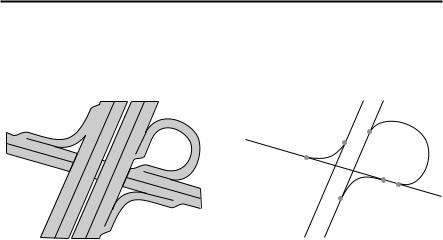
The position and movements of the vehicle are recorded by the navigation system’s sensors. The distance travelled is determined by the vehicle speedometer signal, rotary motion in curves is detected by a gyro sensor (inertial compass). The position is determined via the GPS (Global Positioning System) satellites.
The position can be calculated within a range of approx. 10 m by comparing the sensor signals with the digital map on the navigation CD.
English
Important notes on the function of your navigation radio
In principle, the system is functional with poor GPS reception, although the accuracy of the positioning may be impaired by poor or interrupted GPS reception or errors can occur in the determination of the position, which result in incorrect position reporting.
Start-up characteristics
If the vehicle is parked for longer periods of time, the satellites continue their orbit. After the ignition is switched on, it may take several minutes until the navigation system receives signals from sufficient satellites for evaluation.
During the start-up sequence, it is possible that the navigation system will report: “You are leaving the digitised area”. The navigation system assumes that the vehicle is located outside a digitised area. If other roads exist in this area, the navigation system may issue incorrect messages. The navigation system assumes that the vehicle is located on another road.
Comments
After transport of the vehicle by train or ferry, the navigation system may require a few minutes for exact positioning.
After disconnecting the vehicle battery, up to 15 minutes may be required for exact positioning. For this, the vehicle must be outdoors and the system must be switched on in order to receive transmissions from the GPS satellites.
11
GENERAL INFORMATION
The digital road map
To be able to plan a route to a destination address, the navigation system not only requires the current position of the vehicle but also a digital road map containing the destination address itself and the roads leading to the destination address. This digital road map is on the map CD which you insert into the navigation computer.
|
|
|
Real road network |
|
Digital line model |
The road system is stored on the map CD as a line model, i.e. even large junctions have only one focal point that is approached by all roads in point-to-point fashion. Thus the navigation system indicates the distance to the turn-off point as the distance to the centre of the junction. This is why the distances indicated on main road signs may not agree with those of the navigation system. The road signs indicate the distance to the beginning of the exit.
Areas with limited road information
In some areas, not all of the information on a road is available on the map CD. Thus, for example, turn-off prohibitions, information on the direction of travel in a one-way street or prohibited entry into a pedestrian zone may be missing. The navigation system will display a warning if you drive into such an area. Local traffic laws always take precedence over navigation system instructions. Always observe the road signs and motor vehicle traffic regulations.
Topicality of the map CD
Roughly 10 - 15% of the road system characteristics change each year. Due to these constantly changing traffic conditions (construction of new roads, traffic calming, etc.) we cannot guarantee that the digital road map will be in 100 % agreement with existing traffic conditions. We recommend that you always use the most current version of the map CD for navigation.
12

GENERAL INFORMATION
Route & Sound - Navigating and listening to an audio CD
With the new generation of our navigation radio units, you may insert
a map CD, plan your route, then insert an audio CD and the system will
still guide you to your intended destination. The navigation computer saves the road system in a defined area around the planned route
(corridor) in its main memory. Within this corridor, the map CD does not have to be inserted in order for the navigation to function. As soon as you leave this corridor, a message will appear automatically, prompting you to insert the map CD so that the navigation computer can reload the data required for a new route.
■ Expanded Route & Sound function
What is meant here is destination input without a map CD. If the new destination is within the range of the map section (corridor) stored in the main memory, it is possible to enter a new destination without the map CD.
What is meant by “corridor” ?
The navigation system plans a route and then loads a “belt” around the planned route (the corridor) as map data from the map CD into the main memory.
Functional restrictions in corridor mode
Please note that some navigation system functions are not or only partially available when the map CD (corridor mode) is not inserted.
In this event, the menu options appear grey (e.g. Alternative route, Route selection, Traffic info away from the planned route).
It is only possible to load stored addresses if they are located within the corridor. Route planning is only possible with roads located within the corridor. Even if a destination address is located within the corridor and can be entered as a destination, it may not be possible to plan a route to that destination. In this case, please insert the map CD.
TMC traffic information is only available for the map region stored in the corridor. Travel info and POIs can only be called up using the map CD.
Some C-IQ functions (in particular code entry) are only possible when the map CD is inserted.
As soon as you insert the map CD, these functions are available again.
Leaving the corridor
If you leave the corridor, e.g. if you are not following the planned route, the navigation system will attempt to guide you back into the corridor. The directional arrow and the distance to the planned route will be displayed.
When leaving the corridor (more than approx. 3 km), the navigation system will display only the directional arrow and the distance to the destination.
In this case, please insert the map CD so that the navigation system can plan a new route to your destination.
English
13

GENERAL INFORMATION
RDS (Radio Data System)
Many FM stations transmit RDS information. The navigation radio evaluates the RDS telegram and offers the following advantages:
–PS (Program Service Name): Display of station name,
–PTY (Program TYpe): Station selection by program type, page 31
–AF (Alternative Frequency): Automatic re-tuning to best alternative frequency,
–TA (Traffic Announcement): Traffic announcements , page 25
–EON (Enhanced Other Networks): Automatic fading in of traffic announcements on other stations, page 26
–NEWS: Fading in of messages and items of news, page 25
–TMC (Traffic Message Channel): Traffic information for dynamic navigation,page 25
Notes on audio CDs
You can play 12 cm audio CDs on your CD player. The use of 8 cm CDs (with or without adapter) and of CDs with irregular shapes is not recommended.
Notes on map CDs
The navigation system is based on a C-IQ database, which is stored on a CD in encrypted format. The CD contains map data for navigation as well as travel and traffic information (TMC) for dynamic route planning. You can customise your navigation package by activating specific components of the database.
For further information see “C-IQ - INTELLIGENT CONTENT ON DEMAND”, page 39.
Support of compressed map data
As of version 2004/02, the map and travel info content is compressed on the map CDs in order to make further useful C-IQ content available to you.
The new map CDs can then only be read using this operating software version or higher.
Handling CDs
Avoid leaving fingerprints on the CD when removing it.
Always store map and audio CDs in their protective covers.
Always ensure that CDs are clean and dry before inserting.
Protect CDs from heat and direct sunlight.
14

INSTALLATION INSTRUCTIONS
IMPORTANT INFORMATION
Please read this information carefully and follow the all the instructions outlined below. This will ensure the reliable operation and long service life of your navigation radio.
Keep the packaging and operating instructions in a safe place in order to pass them on to a subsequent owner in the event of selling the unit at a later date.
AOnly trained specialists may install the unit.
AObserve automotive industry quality standards.
AFire hazard! When drilling, care must be taken not to damage concealed wiring harnesses, the fuel tank and fuel lines.
ANever drill into supporting or safety-relevant body parts.
AOnly install in vehicles with 12V on-board voltage and negative earth. Risk of malfunction, damage and vehicle fire if installed in unsuitable vehicles (e. g. heavy goods vehicles, buses).
AAlways observe correct assignment of vehicle connections. Incorrect assignment of the connections may lead to damage of the unit or vehicle electrical system/electronics.
Connection in vehicles equipped with standard ISO connectors
The navigation radio may be installed without major preparation in vehicles equipped with ISO standard connectors. Some signals may have to be connected to ISO connector A (refer to “Connection overview ISO chamber A”).
For vehicles with different connection requirements, ask your dealer for special leads for a problem-free installation.
Connection in vehicles without standard ISO connectors
If no adapter leads are available for your vehicle, connect the navigation radio as described in “Electrical connections”.
Taking safety precautions, Fig. 1
A Before starting work, disconnect the earth lead from the negative terminal of the vehicle battery in order to prevent short circuits. For this purpose, follow the vehicle manufacturer’s safety instructions (alarm system, airbag, immobiliser, etc.).
Making the electrical connections
Route all wiring with care. For wiring details, refer to the connection diagram on the back fold-out page and the following table.
Do not cut non-assigned wires. Instead, wind them together and secure to one side. They may be required for retrofitting additional functions.
English
15

INSTALLATION INSTRUCTIONS
Connection overview, ISO chamber A, Fig. 2:
Pin Connection
A1 Input digital speedometer signal / SDVC
A2 Switch input reversing signal (reversing light plus)
A3 Switch input telephone mute function
A4 + 12 V permanent positive; terminal 30
A5 Switch output for electronic antenna /relay motor antenna
A6 Switch input pilot light
A7 +12 V ignition positive; terminal 15 (without switch-off on starting engine)
A8 Battery negative; terminal 31
A Only connect electrical signals to suitable connecting points in the vehicle.
A If separate connection is made directly to the battery, protect the positive lead with a
10 A fuse close to the battery (max. distance 10 to 15 cm).
■ Digital speedometer signal (A1):
A digital speedometer is required for correct functioning of the navigation system. Analogue speedometer signals are not supported by the system.
A
Connect pin A1 to the vehicle speedometer signal.
Never collect the speedometer signal directly from the ABS control or the CAN bus.
Digital speedometer signal requirements:
Frequency: 0 Hz - 4 kHz square-wave signal (no inductive sensor)
Low - level: < 1 V
High - level: 4 V - 24 V
Notes: Many vehicles are equipped with a digital speedometer signal on one of the radio connectors. Notes on vehicle-specific information regarding the speedometer signal and the above-mentioned accessories can be obtained from your installation service or from our Customer Help Desk.
Operation of the navigation system is possible without a speedometer signal. However, in the absence of a speedometer signal the following functional restrictions may arise:
–Inaccurate navigation
–Inaccurate or invalid information in trip computer
–Limitations with regard to SDVC (speed-dependent volume control)
If your vehicle is not equipped to produce a digital speedometer signal, an optional speed sensor can be installed. This is available as an accessory from your installation service.
Mechanical speedometer
A digital speedometer signal can be obtained through the installation of a VDO X39-397-106-191 speed sensor in the speedometer drive shaft.
CAN bus
In many vehicles, speed, reversing and light information can be read out from the vehicle’s CAN bus and converted into the appropriate signals for the navigation system using an adapter.
Universal installation
If none of the above-mentioned options are possible, the wheel speed can be converted into a digital speedometer signal by means of an MA 3400/00 magnetic field sensor and magnetisation of a tyre.
16

INSTALLATION INSTRUCTIONS
■ Reversing signal (A2):
Connect pin A2 to a suitable reversing signal point (positive lead of reversing lamp). Note: Operation of the navigation system is not possible without a reversing signal.
The absence of a reversing signal may lead to inaccurate navigation.
■ Telephone mute function (A3), optional:
Connect pin A3 to the mute function output of the car phone or the hands-free unit. When the telephone is in use, the radio is muted or the telephone conversation is amplified via the car loudspeakers. See also “Green connector C2” on the following page.
■ 12 V permanent positive (A4):
Connect pin A4 to a suitable connector with 12 V permanent positive.
A This connection should be rated for a current of at least 10 A.
■ Electronic antenna / motor antenna (A5), optional:
Connect pin A5 to the supply lead of an electronic antenna or to the control lead of a motor antenna.
A Do not use this connection to supply the antenna motor.
■ Pilot lighting (A6), optional:
Connect pin A6 to a suitable connector of the low-beam positive lead.
When the low beam is switched on, the pilot lighting at the volume control is illuminated, even when the radio is switched off.
■ 12 V ignition positive (A7):
Connect pin A7 to a suitable 12 V circuit switched through the ignition.
Connection overview ISO chamber B (loudspeakers), Fig. 3:
Pin |
Connection to loudspeaker |
B1 + Rear right (RR+)
B2 - Rear right (RR-)
B3 + Front right (FR+)
B4 - Front right (FR-)
B5 + Front left (FL+)
B6 - Front left (FL-)
B7 + Rear left (RL+)
B8 - Rear left (RL-)
AUse only loudspeakers of 4 Ohms impedance.
ADo not connect the loudspeakers to earth.
ADo not connect the booster/amplifier directly to the loudspeaker outputs.
ADo not connect loudspeakers via an external fader.
To check the correct connection of the loudspeakers the function “Loudspeaker Test” in the “INITIALISATION” menu can be performed.
English
17

INSTALLATION INSTRUCTIONS
Optional connections ISO chamber C, Fig. 4 - 6
■ Line-out (yellow connector C1):
(adapter cable, accessories)
An amplifier with additional loudspeakers can be connected to the unit via this connector.
■ Telephone input (green connector C2):
(adapter cable, accessories)
Connect the loudspeaker output of your mobile phone or hands-free unit to lead C2.
For information about setting the telephone attributes, refer to “INITIALISATION” in the operating instructions.
■ TMC receiver (connector C2):
(adapter cable, accessories)
You can connect an MT 5011 dynamic TMC receiver to the unit.
For installation and connection details, refer to the TMC receiver installation instructions.
Following connection, the TMC receiver must be registered with the navigation radio in order to specify it as the TMC source for the navigation system.
Activate the “Ext. TMC Receiver” in the “Settings –> TMC source” menu, in order to use the TMC receiver as the source for traffic announcements.
The new setting is only active after re-starting the system.
■ Steering wheel remote control (connector C2):
(adapter cable, accessories)
In some vehicles, many radio functions can be controlled using the vehicle-specific steering wheel remote control. In order for this to be possible, the steering wheel remote control must be connected to the radio using an adapter cable. Ask your dealer for the appropriate adapter cable.
■ CD changer (blue connector C3):
You can connect a digital CD changer to the unit. Please contact the service department or your dealer for information on suitable CD changers.
For connection details, refer to the CD changer installation instructions.
Installing the GPS antenna, Fig. 7
The GPS antenna may be installed in the passenger compartment, for example on the dashboard or the rear shelf. The antenna needs to have unrestricted “visual contact” to the sky.
Clean the mounting surface and attach the antenna with the double-sided adhesive strip.
Vehicles with metallised windows should have the antenna installed on the boot lid, on the roof or in the plastic bumper.
Note: To guarantee the functioning of the antenna, maintain a minimum distance of 10 cm to any metal parts (window frame, etc.) during installation.
18

INSTALLATION INSTRUCTIONS
Install installation bracket, Fig. 8 - 10
The navigation radio can be installed into a vehicle’s DIN radio slot using the installation bracket provided.
■ Note before installing, Fig. 13:
The radio must be installed horizontally. Deviations of - 10 to + 30 degrees can be set in the “Mounting angle” menu (see “Initial operation”). Larger deviations may result in malfunctions.
A rigid connection to the vehicle body is a prerequisite for correct functioning of the system
Insert the installation bracket into the DIN slot and bend the appropriate metal tabs inwards using a screwdriver (Fig. 10). Take care not to damage any hidden parts in the dashboard.
Mounting the radio, Fig. 11
1.Connect the GPS antenna connector to the GPS antenna socket on the back of the unit.
2.Insert antenna plug E into antenna socket. If necessary, use a suitable antenna adapter. Use hook (J) on the back of the unit for secure attachment.
3.Insert ISO plug A (power supply) into the radio ISO socket A'.
4.Insert ISO plug B (loudspeakers) into the radio ISO socket B'. If extensions are to be connected to the unit (optional):
5.Push all chamber C connectors together and plug them into the radio ISO socket C'. Push the green connector C2 between the yellow connector C1 and the blue connector C3. At least one of these connectors is required for C2 to engage into the socket:
Yellow connector C1: Left chamber of ISO socket C1'. Green connector C2: Centre chamber of ISO socket C2'. Blue connector C3: Right chamber of ISO socket C3'.
6.Push the unit into the installation bracket until it engages.
Initial operation, Fig. 12
1.Reconnect the battery.
2.Restore complete functioning of the electrical system (clock, trip computer, alarm system, airbag, immobiliser, etc.).
3.Switch on the ignition.
4.Insert the map CD in the radio. To register the system and enable map, travel guide and/or traffic info, see the operating instructions, Section “C-IQ”.
5.Park the vehicle outdoors to ensure unimpeded GPS reception.
6.Switch on the ignition and the radio.
7.Press the NAV / NAVIGATION button and confirm the user information. The main menu appears. The navigation radio will now initialise.
After connection of the power supply, the integrated GPS receiver requires approximately 2 to 10 minutes until GPS reception is satisfactory.
k
English
19

INSTALLATION INSTRUCTIONS
■ Setting the mounting angle
In order to ensure perfect functioning of the system, the navigation radio must be set to the actual mounting angle in the instrument panel.
1.In navigation mode:
Select the “Mounting angle” option in the “System settings” menu.
2.Depending upon the installation, set the angle to between -10 and +30 degrees. The system does not differentiate between negative and positive angles. Thus, even for a mounting angle of e.g. -10 degrees, set a value of “10” in the menu.
■ Loudspeaker test
To check that the loudspeakers are connected correctly, page 37.
■ Setting the time zone and time format
To set the desired time format (12 or 24-hour) and the time zone appropriate to your location, page 37.
Checking the vehicle functions
A Check the safety-relevant vehicle functions only when the vehicle is stationary, or moving at low speed. Only perform the check in an open area.
Brake system, alarm system, lights, immobiliser, speedometer, trip computer, clock.
Checking GPS reception and calibrating the system
Enter a destination and select “Guidance”. Call up the “GPS / Compass” information menu via the guidance screen (see operating instructions) and check the number of satellites. For a sufficiently exact location determination, the number should be between 4 and 8.
As soon as adequate GPS reception is available, perform a short test drive (approx. 10 minutes) on digitised roads in order to calibrate the system. Calibration takes place fully automatically. Turn off several times and drive through a number of junctions.
Then check whether the navigation system indicates the correct vehicle position in the “Car position” information menu.
Note: The system can also be calibrated without C-IQ contents activated. However, no directional information will be provided. The current vehicle position can then be checked in the emergency menu (see operating instructions).
Removing the radio, Fig. 14
The radio can be released using the pair of U-shaped removal tools supplied.
Push both U-shaped tools into the small holes to the right and left of the unit front until they are felt to engage.
Gently push the tools outwards and carefully pull the radio out of the installation bracket using the tools.
20
OPERATION
Control elements
15 |
|
14 |
|
13 |
|
12 |
|
11 |
|
10 |
|
9 |
1 |
MUTE |
RADIO BAND |
|
MS 4150 |
CD.C |
|
|
|
2 |
SOUND |
|
|
INFO |
1 |
2
3
POWER |
VOLUME |
NAV |
ALT-R |
|
CLEAR |
8 |
4 |
MENU |
|
 5
5
 6
6
SCAN
English
|
|
|
|
|
|
|
|
|
|
|
|
|
|
|
3 |
|
4 |
|
|
5 |
|
|
6 |
|
7 |
|
|
1 o |
Release button for operating panel |
|
|
|
|
||||||||
|
|
|
|
||||||||||
2 SOUND . . . . . . . |
. Opens the “SOUND” menu. page 27. |
|
|
|
|
||||||||
3 POWER/VOLUME . Press: Switching on / off |
|
|
|
|
|||||||||
|
|
Turn: Setting the volume |
|
|
|
|
|||||||
4 INFO . . . . . . . . . |
. Opens the “INFORMATION” menu. page 25. |
|
|
||||||||||
5 1 ... 6 . . . . . . |
. . |
. Radio mode: Preset button |
|
|
|
|
|||||||
|
|
Briefly press preset buttons : Select station memory, |
|||||||||||
|
|
Press and hold: Storing selected station on preset button |
|||||||||||
|
|
CD changer mode: Selection of CD 1 to 6 in the changer magazine. |
|||||||||||
6 MENU . . . . . . . . . Opens the relevant settings menu, depending on the mode (Radio, CD, CD changer, NAV)
7 SCAN . . . . . . . . . . Turn: Moves the cursor in the menus. Press: Confirms a selection in the menus.
For radio, CD and CD changer: Search and scan functions
8 CLEAR . . . . . . . . . Deletes the last entry / Returns to the next higher menu level
9 ALT-R. . . . . . . . . . Planning an alternative route in navigation mode. page 23.
0 NAV. . . . . . . . . . . Opens the navigation menu. page 23.
q {. . . . . . . . . . . . Play back current direction and (if available) the current TMC message. pages 52, 54.
w . . . . . . . . . . . . . . |
Display |
e CD•C . . . . . . . . . |
Switch to CD player, page 34 / CD changer (only with |
|
connected CD changer). page 36. |
r RADIO . . . . . . . . |
Switch to radio mode. page 30. |
BAND . . . . . . . . . |
Opens the “BAND SELECTION” menu (in radio-modus). page 29. |
t MUTE. . . . . . . . . . With mobile phone connected: Switch to telephone input Without mobile phone connected: Muting the system.
21
OPERATION
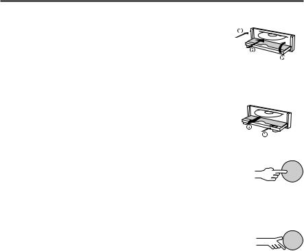
Inserting a CD
1. Open the front panel.
2. Insert the CD into the drive (printed side up).
For audio CDs, playback starts automatically. 3. Close the front panel.
Removing a CD
1.Open the front panel.
2.Press the eject button.
3. Carefully remove the CD and close the front panel.
Switching on / off
Press the POWER/VOLUME knob to switch the unit on or off.
Volume
A When setting the volume, please make sure that traffic noises (horns, sirens, emergency vehicles, etc.) are still audible.
Turn the POWER/VOLUME knob to set the volume.
Setting the volume of the navigation messages
The volume of navigation messages can be modified whilst a message is playing by turning the POWER/VOLUME knob.
Press the { button to hear a navigation message and set the NAV volume.
Setting the volume of traffic announcements
The volume of traffic announcements can be set in the “INFORMATION” menu.page 25.
MUTE
Press MUTE to activate/deactivate the mute function.
Notes:
The current navigation message can be played whilst the system is set to mute by pressing the { button.
No traffic announcements or navigation messages are made when muting is activated. Should you nevertheless wish to hear traffic announcements (with TA Scan activated) and navigation information without the radio or CD playing, simply turn the volume to zero on the unit. The announcements and information are then output at the preset volume (“TA volume” or “NAV volume” in the “INFORMATION” menu).
22
OPERATION
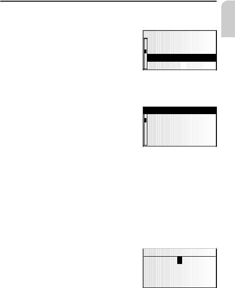
Menu operation
Cursor
The currently selected line or field on the screen is designated as the cursor. The cursor is identified by an inverse field (bright letters on black background).
Move the cursor by turning the right rotary control.
Confirm by pressing the right rotary control.
To confirm, the cursor will be displayed briefly as a frame around the selected field.
Currently non-available options appear grey.
System settings Guidance screen Dyn. route sett. Language Measuring


 units
units


Scroll bar
All menus display a scroll bar on the left side of the screen. It shows the part of the menu in which to find the cursor.
Move the cursor to a menu entry at the top or bottom of the screen by turning the right rotary control.
Turn the right rotary control further in the same direction.
Return  Guidance screen Dyn. route sett. Language Measuring units
The screen automatically displays the next menu items.
In all menus except the main control, the menu title changes to the “Return” option
when you move the cursor to the top of the screen.
Confirm “Return” by pressing the right rotary control to quit the menu
or
Turn the right rotary control further to the left to move upwards in the menu.
You can also quit a menu by pressing the CLEAR button.
Entering letters
Characters are entered by selecting letters from a list. In the following, this type of entering will simply be called “typewriter”.
Move the cursor to the desired letter by turning the right rotary control.
Confirm by pressing the right rotary control.
Non-selectable letters are displayed as dots and will be passed over automatically by the cursor.
City:W_ |
|
|
|
A... |
E... |
|
I.....O.. |
...U |
... |
Y |
... |
g ‰ ¡ Z ¯ ® – |
|||
k
English
23

OPERATION
Options for entering characters
The line at the bottom of the display displays command symbols which allow you to perform the following functions:
c : Destination country selection (in this case, “D” for Germany). ƒ : Save an address in the personal address book.
‰ : Jump to menu “Special dest.”. page 48.
¡: Delete the character entered last.
Š: Direct input of road name without previously entering the name of the city (depending on map CD).
Z : Cancel entry and return to the start of the destination entry. ¯ : Display a list of database items.
® : End of destination input and automatic start of guidance.
– : Accept the data entries and go to the next input step. o : Accept the data entries (e. g. when entering a CD title).
Depending on information already entered, one or more options may not be selectable (grey).
Intelligent “typewriter”
When you enter names of cities and roads or special destinations, the system compares the character string already entered with all database entries on the map CD.
Once you select a character, you will notice that only certain letters remain displayed. The navigation system automatically completes entries if only one possible entry is left.
Different input methods
The database allows you to enter the different parts of compound city or road names in varying sequence. Thus, you may begin entering “Frankfurt am Main” by inputting “FRANKFURT” or “MAIN”.
The input methods depend on the map CD inserted. Not all map CDs support this function.
Entering special characters
The typewriter provides the space and the period and, depending upon the language selected, certain country-specific accented characters. If you have selected a system language for which accented characters for the names of cities and roads are not supported, you can enter the name without accented characters (e.g. “MUNCHEN” instead of “MÜNCHEN”).
For “ß”, enter “ss”.
24
 Loading...