


|
|
|
|
|
A |
|
|
|
|
|
|
|
|
|
T TE |
|
|
|
|
||
|
|
DS |
|
S S |
|
|
|
|||
|
E |
|
|
|
|
T |
|
|
||
T |
|
|
|
|
|
|
|
|||
|
|
|
|
|
|
O |
|
|||
I |
|
|
|
|
|
|
|
|
||
N |
|
|
|
|
|
|
|
|
V |
|
|
|
|
|
|
|
|
|
|
E |
|
U |
|
|
|
|
|
|
|
|
|
|
USSC |
|
|||||||||
|
|
|
C |
|
|
Y |
|
|
|
|
|
|
|
|
OMPAN |
|
|
|
|
||
Installation/Operator’s Manual
Model: 1600EF
Wood or Coal External Furnace
SAFETY NOTICE:
If this furnace is not properly installed, a house fire may result! For your safety, follow these installation instructions. Contact local building or fire officials about restrictions and installation requirements in your area. This furnace must be installed by a qualified technician. Keep these instructions for future reference.
Safety Tested to UL 391
United States Stove Company • 227 Industrial Park Road, P.O. Box 151 • South Pittsburg, TN 37380 • www.usstove.com
USSC |
851846 rev 01 |
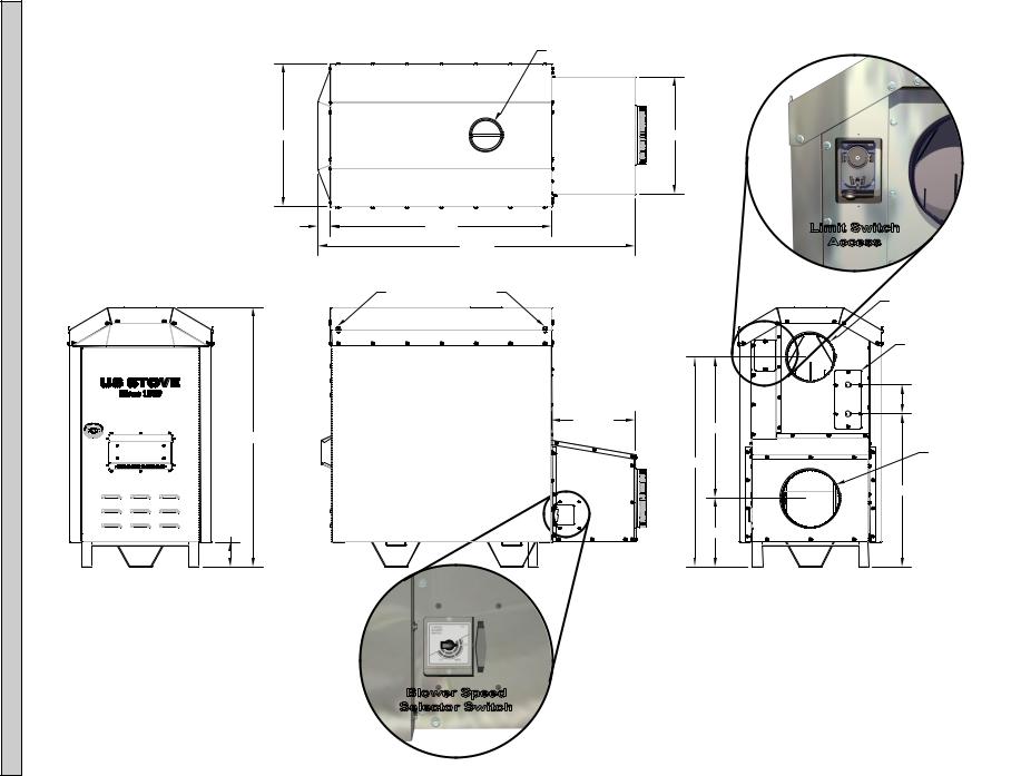
UNIT DIMENSIONS
USSC
6” FLUE GAS OUTLET
29-1/2” |
24-1/4” |
2-9/16” |
45-3/4” |
Limit Switch |
|
65-1/2” |
Access |
|
|
|
|
D-RINGS FOR GUY WIRE |
|
|
ATTACHMENT |
10” HOT AIR OUTLET |
|
|
55-5/8”
5-3/16”
17-5/16” |
HOT WATER COILACCESS |
(OPTIONAL) |
6” |
29-3/16” |
12” COLD AIR RETURN |
43-7/16” |
31-5/8” |
14-1/4” |
Blower Speed
Selector Switch
2
" CUT HERE
" CUT HERE
WARRANTY INFORMATION CARD
Name__________________________________________Telephone#:(_____)_____________
City____________________________________________ State_______ Zip_________________
Email Address __________________________________________________________________
Model # of Unit________________________________ Serial #___________________________
Fuel Type: qWood qCoal qPellet qGas qOther_________________________
PlaceofPurchase(Retailer)______________________________________________________
City____________________________________________ State_______ Zip_________________
If internet purchase, please list website address___________________________________
Date of Purchase _______________________________________________________________
Reason for Purchase: |
qAlternative Heat |
qMain Heat Source |
qDecoration |
qCost |
qOther_________________________ |
What was the determining factor for purchasing your new USSC appliance?_______
I have read the owner’s manual that accompanies this unit and fully understand the: Installation q Operation q and Maintenance q of my new USSC appliance.
Print Name |
Signature |
Date |
Please attach a copy of your purchase receipt. Warranty not valid without a Proof of Purchase.
Warranty information must be received within 30 days of original purchase.
Detach this page from this manual, fold in half with this page to the inside and tape together. Apply a stamp and mail to the address provided. You may use an envelope if you choose.
You may register online by going to www.usstove.com
All information submitted will be kept strictly confidential. Information provided will not be sold for advertising purposes. Contact information will be used solely for the purpose of product notifications.
" CUT HERE
ÊFold Here |
Fold HereÉ |
PLACE
STAMP
HERE
United States Stove Company
P.O. Box 151
South Pittsburg, TN 37380
CUT HERE
"
INTRODUCTION
Thank You for your purchase of a U.S. Stove Wood/Coal Burning External Furnace. Your decision to buy our Clayton Furnace was undoubtedly reached after much careful thought and consideration. We are very proud you chose this furnace and trust you will receive the comfort and economy that others realize when heating with a U.S. Stove product.
Your dealer is important in your experience with the furnace not only with the purchase, but for recommendations for professional installation for your home. The qualified professional installer has been expertly trained in solid-fuel furnace installation to assure the safety and comfort for your family while saving you money. Trust your experienced installer. They are specialist in this field.
IMPORTANT
Before installing and using your furnace, please read the following pages thoroughly and carefully. If you follow the instructions, your furnace will give you safe and more dependable service for years to come.
•Check your local codes. This installation must comply with their rulings.
•This is an outdoor hot air furnace and must NOT be installed inside the home or a building.
•This furnace must be connected to a 110 volt Ground Fault Circuit Interrupter (GFCI) outlet suitable for outdoor use.
•A back-up generator, 2,000 watts minimum, is recommended in case of a power failure.
•Always have a properly functioning smoke or ionization detector and a CO detector installed in your home.
•To prevent injury or damage, do not allow anyone who is unfamiliar with the furnace to operate it.
•Spend adequate time with your furnace to become well acquainted with the different settings and how each will affect its burning patterns. It is impossible to state just how each setting will affect your furnace because of the variations in each installation.
DISCLAIMER NOTICE
The BTU ranges and heating capacity specifications are provided as a guide and in no way guarantee the output or capacity of this unit. The actual BTU output depends on the type of fuel being burned and its conditions, the thermostat setting, the draft adjustment and the chimney to which the unit is attached. The actual area that this unit will heat depends on factors such as the conditions of the building, heat loss, type of construction, amount of insulation, type of air movement, the location of the unit and more importantly the duct work and return air facility.
Warning:
Do not alter this appliance in any way other than specified in these instructions. Doing so may void your warranty.
GENERAL INFORMATION
Your 1600EF furnace comes ready for installation. No assembly required. Unpack your furnace and insure that there is no shipping damage. If damage exist, please contact your dealer immediately. Review the items included with your furnace located inside the firebox.
1 - 10” Starter Collar
1 - 12” Starter Collar for Cold Air Return
8 - #10 x 3/4 Screws w/ Sealing Washer
1 - Literature Package
This furnace may be installed as a Stand-Alone Central Furnace or as a Supplementary Furnace. If installed as a Central Furnace, this unit will have it’s own central ducting system and will essentially be your primary heat source. If installed as a Supplementary Furnace, the 1600EF will assist an Electric, Gas or Oil Fired Furnace in heating your home by utilizing the existing furnace’s duct work system. The 1600EF must not be wired in conjunction with the existing furnace. The outdoor furnace may be operated with the supplied wall thermostat or a 24 volt thermostat that you supply yourself.
The furnace should be placed outdoors on a level noncombustible base, preferably a 4’ x 8’ concrete pad, as close to the home as clearances to combustibles will allow. If locating the furnace more than 10 feet away from the home, a minimum of 6 feet of Class “A” HT 2100 All Fuel 6 inch chimney pipe is required - Do not place the furnace more than 40 feet away from the home. Maintain all clearances stated in this manual.
Class “A” HT 2100 All Fuel 6” Chimney Pipe is recommended for optimum performance and can be purchased from your local dealer. A Chimney Base Plate should be installed over the flue outlet and sealed to maintain weather resistance. A 2” clearance to combustibles must be maintained from the pipe. We suggest using either Simpson Dura-Vent or Metal Fab chimney products for your installation.
If you choose to use single wall stainless, the flue temperatures will be reduced which promotes the formation of creosote, possibly creating a fire hazard. If you use single wall stainless pipe, the minimum clearance to combustibles is 20”.
Attach the appropriate chimney pipe lengths to the chosen chimney base plate and finish with a rain cap. Secure the chimney with guy wires to each of the four anchors point on the furnace. Your furnace requires it’s own chimney system and can not share a flue with another appliance.
Once you have selected a location for the furnace and connectedyourfurnacetoachimneyanda110voltGFCI outlet, you will need to commence an initial firing. DO NOT connect the furnace to your duct work at this time. Your new furnace has a protective coating of oil and paint on the surface which could produce smoke or odors during the initial firing and will burn off. Build a small fire - DO NOT fill the firebox to it’s full capacity for the initial burn. This initial firing allows the metals and castings to cure.
After completing the firing and allowing it to cool, you are ready to finish the installation. Refer to the remainder of this manual for detailed instructions.
USSC |
5 |
WOOD SUPPLY
Someimportantrulesforpreparinggoodfirewoodare:Cut, split and stack the wood in the early spring and let it stand in the sun and wind all summer.
Whether you purchase your wood or cut it yourself, spring is the best time to buy or cut your wood to insure it is good and dry come winter. If you live in a damper climate, it will take longer for the wood to season.
By far the most important characteristic of any firewood is its moisture content. Firewood with a moisture content higher than twenty percent will burn, but it will be hard to light and keep burning, will make a lot of smoke and will produce less efficient fires with lower sustained BTU output. Plus much of its energy content will be wasted right up the chimney. Firewood should be between 15 and 25 percent moisturetoburnproperlyandtogetthatdryitmustbesplit and stacked in the open for at least a full summer.
All wood burns, but wood that’s cut green (between 50 and more than 100 percent moisture content) burns with more difficulty, because the water in the wood must be boiled off before the actual wood fiber can burn. Air-dried (“seasoned”) wood is generally between 20-30 percent. Kiln-dried firewood generally contains less than 20 percent moisture.
Green wood can produce more creosote--a black sooty liquid which deposits and hardens on the inside of your chimney and can ignite, causing a chimney fire.
When you stack your wood, you should stack it in an open location where the summer sun can warm it and breezes can help remove moisture. Be sure to cover the top of the wood pile to keep the rain out. It is important that you do not stack unseasoned wood in an unventilated area for it will not dry properly. You shouldn’t allow your firewood to lay on the ground for more than a couple days before stacking , or it will start to mold and rot quickly.
Once your wood is seasoned, store it in a dry location before burning.
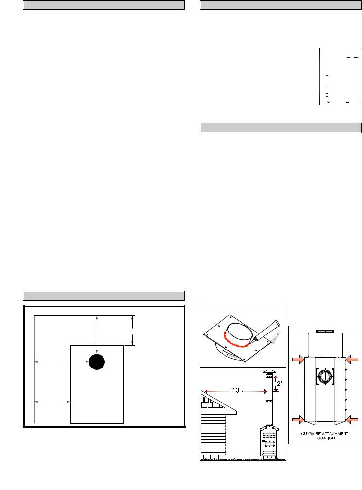
CLEARANCES
COMBUSTIBLE WALL
|
20” |
15” |
|
|
|
WALL |
|
(TOP VIEW) |
COMBUSTIBLE |
22” |
MINIMUM CLEARANCES |
|
||
FLUE |
TO A COMBUSTIBLE |
|
WALL |
||
|
CAUTION: |
|
|
|
|
|
|
DO NOT store |
|
12” |
combustible or |
|
flammable materials or |
|
|
|
|
|
|
liquids near the |
|
|
furnace. |
Sides of furnace, 12”; Rear of furnace, 15” (allow approximately 20” for the return box); Front of furnace, 36”; Heat Duct, 2” for the first 9 feet then 1” thereafter.
6
FLUE PIPE INSTALLATION
Clearancestocombustiblematerialswillvarywiththetype of flue connection used. Be sure to maintain the specified clearances for your type of installation.
TYPE OF FLUE |
REQUIRED |
||||||
CONNECTION |
CLEARANCE |
||||||
.....Class A 103HT All-Fuel or Equivalent 2” |
|
|
|
|
|
|
|
................Double Wall, Stainless Steel or |
6” |
|
|
|
|
|
|
Double Wall, Black Pipe w/ |
|
|
|
|
|
|
|
Stainless Steel Inner wall |
|
|
|
|
|
|
|
|
|
|
|
|
|
|
|
24 Gauge or Heavier |
20” |
|
|
|
|
|
|
|
|
|
|
|
|
||
Single Wall Stainless Steel |
|
|
|
|
|
|
|
|
|
|
|
|
|
|
|
or Black Pipe |
|
|
|
|
|
|
|
|
|
|
|
|
|
|
|
|
|
|
|
|
|
|
|
The above clearances to combustibles must be maintained.
CHIMNEY REQUIREMENTS
AClass“A”HT2100AllFuel6”ChimneyPipeandBasePlate should be used for the installation. See Illustration. Place the Base Plate over the flue outlet of the furnace and drill eight(8) pilot holes into the Cabinet Top. Apply a generous amount of high temperature sealant to the bottom of the base plate, and around the flue outlet. Position the base plate over the flue and secure with the eight(8) screws provided. Then attach the flue pipe sections.
Aminimumchimneyheightof6feetisrequirednotincluding the rain cap. In order to determine proper chimney height abovetheroof,measurefromthesideofthechimneyhorizontally.Asyoumoveupthechimney,thelengthincreases. Once this measurement reaches 10 feet, this is the base height of the chimney. The chimney must be 2 feet taller than the base height. If the chimney is closer than 10 feet fromthepeakoftheroof,thechimneymustbe2feettaller than the peak of the roof. The 2 feet measurement does not include the rain cap.
Once correct chimney height is achieved, check the chimney draft. It should not exceed 0.06 inches of water column. Then secure with three screws at each joint and attachguywiresdowntotheringslocatedaroundthetop of the furnace cabinet.
See illustration.
USSC |
CONNECTING HOT AIR DUCT
TO FURNACE
We strongly recommend that the hot air duct work be installed by a home heating specialist. If doing the installation yourself, before you decide which installation will bestsuityourneeds,consultaqualifiedheatingtechnician and follow his recommendations as to the safest and most efficient method of installation.
The warm-air supply-duct system shall be constructed of metal in accordance with NFPA 90B, 2-1.1. The plenums installed to the furnace be constructed of metal in accordance with NFPA 90B, 2-1.3.
Outside the house you must use 10 inch galvanized pipe, wrapped with weather proof, UV resistant insulation. The 12 inch return may be galvanized pipe and attached to the home so as to not pressurize the home.
NEVER reduce the 10” hot air or the 12” return air as this will result in restricted air flow and cause the furnace to not operate properly.
NEVER draw cold outside air into the blower housing. By doing so, the furnace’s heat chamber will not reach the necessary temperature to heat the home.
The duct work should be designed so the external static pressure does not exceed 0.2 inches water column while
developing air velocities of 600 to 1,000 feet per minute
in the main trunk duct and 400 to 600 feet per minute at the registers. The heat outlet should never be less than ten inches (10”) round or 79 square inches.
This furnace must be installed with a cold air return system.
The system must be a minimum of twelve inches (12”) to readily transfer the cold air from the home back to the furnace.Ifdesired,acoldairfilterboxmaybeconstructed with a minimum opening of 225 square inches.
The warm-air supply outlet of the outdoor furnace must not be connected to the cold-air-return inlet of an existing centralfurnacebecausethepossibilityexistofcomponents of the existing furnace overheating and may cause the central furnace to operate other than intended.
TYPES OF INSTALLATION
NO DUCT WORK INSTALLATION
Cold air return must be installed in all installations, even those without an air duct system. If you do not, the furnace will not be able to heat the home. A filter should be installed in the cold air return. Furnace filters should be checked and cleaned/replaced regularly.
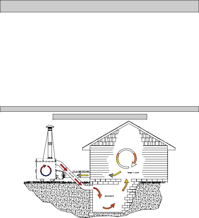
When there is no duct system to connect the furnace to, keep the following in mind:
1. You must separate the hot air duct from the cold air |
2. In homes with a basement, you may run the hot air |
return. Ideally, locate each at opposite ends of the |
duct to the basement and pull the cold air return from |
home. This method will work well in homes that are built |
the main floor. This will create the perfect air flow since |
on concrete slabs and should create a good air flow. If |
hot air rises. |
you do not, air will not flow evenly through the home. |
|
USSC |
7 |

TYPES OF INSTALLATION continued...
CENTRAL DUCT CONNECTION
When connecting to a central duct system, avoid 90 degree elbows as this will reduce air flow delivery. A duct run in excess of 40 feet is NOT RECOMMENDED. The air flow and heat output will be greatly decreased.
Run 10” insulated hot air duct from the outdoor furnace through a wall or window of the structure. Then attach a flexible hot air duct to the existing duct work. Connect the duct with a 45 degree elbow or at an angle so the hot air from the outdoor furnace is delivered downstream. This will insure proper air flow into the system.
Avoid delivering hot air through an air conditioning coil as this will cause an obstruction reducing heat output.
The following illustrations may be used as examples for your installation.
INSTALLATION EXAMPLES
INSTALLATION #1
With this installation, a back draft damper (optional) is inserted into the heat run before the plenum of the existing furnace to prevent air from the existing furnace to blow back into the furnace when it is not in use. When a back damper is employed, it should be located as close to the existing furnace plenum as practical.
INSTALLATION #2
The baffle on this system should be made the full width of the furnace plenum in order to properly direct the air into the distribution ducts.
INSTALLATION #3
Extendingthehotairductfromthefurnaceintotheexisting plenum will help direct the flow of air from the furnace as well as the flow in the existing furnace. Ducting entering theexistingplenumatanangle(approximately45degrees) will facilitate air flow from the furnace while diverting air from the existing furnace.
8 |
USSC |
 Loading...