


Precautions
Before you use this scanner, please observe the following:
WARNING!
Uniden America Corporation does not represent this unit to be waterproof. To reduce the risk of fire, electrical shock, or damage to the unit, do not expose this unit to rain or moisture.
IMPORTANT!
•This scanning radio has been manufactured so that it will not tune radio frequencies assigned by the FCC for cellular telephone usage. The Electronic Communications Privacy Act of 1986, as amended, makes it a federal crime to intentionally intercept cellular or cordless telephone transmissions or to market this radio when altered to receive them.
•The installation, possession, or use of this scanning radio in a motor vehicle may be prohibited, regulated, or require a permit in certain states, cities, and/or local jurisdictions. Your local law enforcement officials should be able to provide you with information regarding the laws in your community.
•Changes or modifications to this product not expressly approved by Uniden, or operation of this product in any way other than as detailed by this Operating Guide, could void your authority to operate this product.
•The screen displays used in this manual are representations of what might appear when you use your scanner.
May be covered under one or more of the following U.S. patent:
4,627,100 |
4,841,302 |
4,888,815 |
4,932,074 |
4,947,456 |
5,014,348 |
5,199,109 |
5,408,692 |
5,428,826 |
5,438,688 |
5,448,256 |
5,465,402 |
5,471,660 |
5,483,684 |
5,530,296 |
5,548,832 |
5,551,071 |
5,574,995 |
5,577,076 |
5,598,430 |
5,600,223 |
5,642,424 |
5,710,992 |
5,896,422 |
5,991,346 |
5,991,603 |
6,012,158 |
6,025,758 |
6,034,573 |
6,064,270 |
6,266,521 |
|
|
|
|
**U.S. Patent Number 4,841,302 is licensed from Gray Electronics, Inc.
**These products contain Uniden proprietary information. Software, control codes, protocols and other such related matter may be the copyrighted work of Uniden America Corporation.
©Copyright 2002-2003, Uniden America Corporation. All Rights Reserved.
©2003 Uniden. This product contains Uniden proprietary information.
Software, control codes, protocols and other such related matter may be the copyrighted work of Uniden America Corporation.
Uniden ® is a registered trademark of Uniden America Corporation.
Bearcat ® is a registered trademark of Uniden America Corporation.

Contents |
|
Introduction . . . . . . . . . . . . . . . . . . . . . . . . . . . . . . . . . . . . . . . . . . . . . . . . . . . . . . . . . . . . . . . . . . . . |
.1 |
Front and Rear Views . . . . . . . . . . . . . . . . . . . . . . . . . . . . . . . . . . . . . . . . . . . . . . . . . . . . . . . . . . . . |
.2 |
Icon Display . . . . . . . . . . . . . . . . . . . . . . . . . . . . . . . . . . . . . . . . . . . . . . . . . . . . . . . . . . . . . . . . . . . . |
.3 |
Terminology . . . . . . . . . . . . . . . . . . . . . . . . . . . . . . . . . . . . . . . . . . . . . . . . . . . . . . . . . . . . . . . . . . . . |
.4 |
What are Highway Patrol Alerts? . . . . . . . . . . . . . . . . . . . . . . . . . . . . . . . . . . . . . . . . . . . . . . . . . . |
.4 |
What is Scanning? . . . . . . . . . . . . . . . . . . . . . . . . . . . . . . . . . . . . . . . . . . . . . . . . . . . . . . . . . . . . . |
.4 |
What is Searching? . . . . . . . . . . . . . . . . . . . . . . . . . . . . . . . . . . . . . . . . . . . . . . . . . . . . . . . . . . . . |
.4 |
What is Trunk Tracking? . . . . . . . . . . . . . . . . . . . . . . . . . . . . . . . . . . . . . . . . . . . . . . . . . . . . . . . . . |
.4 |
Feature Highlights . . . . . . . . . . . . . . . . . . . . . . . . . . . . . . . . . . . . . . . . . . . . . . . . . . . . . . . . . . . . . . . |
.6 |
Where to Obtain More Information . . . . . . . . . . . . . . . . . . . . . . . . . . . . . . . . . . . . . . . . . . . . . . . . . . . |
.7 |
Information on the Internet . . . . . . . . . . . . . . . . . . . . . . . . . . . . . . . . . . . . . . . . . . . . . . . . . . . . . . . |
.7 |
Included with Your Scanner Package . . . . . . . . . . . . . . . . . . . . . . . . . . . . . . . . . . . . . . . . . . . . . . . . . |
.8 |
Optional Accessories . . . . . . . . . . . . . . . . . . . . . . . . . . . . . . . . . . . . . . . . . . . . . . . . . . . . . . . . . . . |
.8 |
Installing the BCT8 . . . . . . . . . . . . . . . . . . . . . . . . . . . . . . . . . . . . . . . . . . . . . . . . . . . . . . . . . . . . . . . |
.9 |
For Home Use (Desktop Installation) . . . . . . . . . . . . . . . . . . . . . . . . . . . . . . . . . . . . . . . . . . . . . . . |
.9 |
For Mobile Use (In-Car Installation) . . . . . . . . . . . . . . . . . . . . . . . . . . . . . . . . . . . . . . . . . . . . . . . . |
.9 |
Typical Mounting Methods . . . . . . . . . . . . . . . . . . . . . . . . . . . . . . . . . . . . . . . . . . . . . . . . . . . . . . . |
11 |
Mounting the Scanner in Your Vehicle . . . . . . . . . . . . . . . . . . . . . . . . . . . . . . . . . . . . . . . . . . . . . . |
11 |
Applying Power for Vehicle Installation . . . . . . . . . . . . . . . . . . . . . . . . . . . . . . . . . . . . . . . . . . . . . . |
12 |
DC power Installation . . . . . . . . . . . . . . . . . . . . . . . . . . . . . . . . . . . . . . . . . . . . . . . . . . . . . . . . . . . |
12 |
Applying Power Using Standard AC Power . . . . . . . . . . . . . . . . . . . . . . . . . . . . . . . . . . . . . . . . . . . |
13 |
Connecting an External Speaker . . . . . . . . . . . . . . . . . . . . . . . . . . . . . . . . . . . . . . . . . . . . . . . . . . . |
13 |
Listening Safely . . . . . . . . . . . . . . . . . . . . . . . . . . . . . . . . . . . . . . . . . . . . . . . . . . . . . . . . . . . . . . . |
13 |
Connecting the Clone Cable . . . . . . . . . . . . . . . . . . . . . . . . . . . . . . . . . . . . . . . . . . . . . . . . . . . . . . |
13 |
Scanning Overview . . . . . . . . . . . . . . . . . . . . . . . . . . . . . . . . . . . . . . . . . . . . . . . . . . . . . . . . . . . . . . |
14 |
Turn the Scanner On . . . . . . . . . . . . . . . . . . . . . . . . . . . . . . . . . . . . . . . . . . . . . . . . . . . . . . . . . . . |
14 |
How Squelch Works . . . . . . . . . . . . . . . . . . . . . . . . . . . . . . . . . . . . . . . . . . . . . . . . . . . . . . . . . . . . |
15 |
Setting the Squelch . . . . . . . . . . . . . . . . . . . . . . . . . . . . . . . . . . . . . . . . . . . . . . . . . . . . . . . . . . . . |
15 |
Highway Patrol Scanning . . . . . . . . . . . . . . . . . . . . . . . . . . . . . . . . . . . . . . . . . . . . . . . . . . . . . . . . . . |
16 |
Selecting the State . . . . . . . . . . . . . . . . . . . . . . . . . . . . . . . . . . . . . . . . . . . . . . . . . . . . . . . . . . . . . |
16 |
Scanning Highway Patrol Frequency . . . . . . . . . . . . . . . . . . . . . . . . . . . . . . . . . . . . . . . . . . . . . . . |
16 |
Highway Patrol Scan Hold . . . . . . . . . . . . . . . . . . . . . . . . . . . . . . . . . . . . . . . . . . . . . . . . . . . . . . . |
17 |
Highway Warning Alert . . . . . . . . . . . . . . . . . . . . . . . . . . . . . . . . . . . . . . . . . . . . . . . . . . . . . . . . . . |
17 |
Alert Tone Volume . . . . . . . . . . . . . . . . . . . . . . . . . . . . . . . . . . . . . . . . . . . . . . . . . . . . . . . . . . . . . |
17 |
Muting the Alert Tone . . . . . . . . . . . . . . . . . . . . . . . . . . . . . . . . . . . . . . . . . . . . . . . . . . . . . . . . . . . |
17 |
Alert Light Adjustment . . . . . . . . . . . . . . . . . . . . . . . . . . . . . . . . . . . . . . . . . . . . . . . . . . . . . . . . . . |
18 |
Skip Frequencies . . . . . . . . . . . . . . . . . . . . . . . . . . . . . . . . . . . . . . . . . . . . . . . . . . . . . . . . . . . . . . |
18 |
Priority Channels . . . . . . . . . . . . . . . . . . . . . . . . . . . . . . . . . . . . . . . . . . . . . . . . . . . . . . . . . . . . . . |
18 |
Trunked Highway Frequency . . . . . . . . . . . . . . . . . . . . . . . . . . . . . . . . . . . . . . . . . . . . . . . . . . . . . |
20 |
Private Bank Scanning . . . . . . . . . . . . . . . . . . . . . . . . . . . . . . . . . . . . . . . . . . . . . . . . . . . . . . . . . . . . |
21 |
Programming Frequencies into Channels . . . . . . . . . . . . . . . . . . . . . . . . . . . . . . . . . . . . . . . . . . . . |
21 |
Deleting a Stored Frequency . . . . . . . . . . . . . . . . . . . . . . . . . . . . . . . . . . . . . . . . . . . . . . . . . . . . . |
21 |
Duplicate Frequency Alert . . . . . . . . . . . . . . . . . . . . . . . . . . . . . . . . . . . . . . . . . . . . . . . . . . . . . . . . |
22 |
Memory Lock . . . . . . . . . . . . . . . . . . . . . . . . . . . . . . . . . . . . . . . . . . . . . . . . . . . . . . . . . . . . . . . . . |
22 |
Scanning Private Bank . . . . . . . . . . . . . . . . . . . . . . . . . . . . . . . . . . . . . . . . . . . . . . . . . . . . . . . . . . |
22 |
Hold/Resume . . . . . . . . . . . . . . . . . . . . . . . . . . . . . . . . . . . . . . . . . . . . . . . . . . . . . . . . . . . . . . . . . |
23 |
Channel Lockout . . . . . . . . . . . . . . . . . . . . . . . . . . . . . . . . . . . . . . . . . . . . . . . . . . . . . . . . . . . . . . |
23 |
Restoring a Locked-out Channel in Hold Mode . . . . . . . . . . . . . . . . . . . . . . . . . . . . . . . . . . . . . . . . |
23 |
Restoring All Locked-out Channels . . . . . . . . . . . . . . . . . . . . . . . . . . . . . . . . . . . . . . . . . . . . . . . . . |
24 |
Priority Scan . . . . . . . . . . . . . . . . . . . . . . . . . . . . . . . . . . . . . . . . . . . . . . . . . . . . . . . . . . . . . . . . . . |
24 |
Changing the Priority Channel . . . . . . . . . . . . . . . . . . . . . . . . . . . . . . . . . . . . . . . . . . . . . . . . . . . . |
24 |
Service Scanning . . . . . . . . . . . . . . . . . . . . . . . . . . . . . . . . . . . . . . . . . . . . . . . . . . . . . . . . . . . . . . . . |
25 |
Band Search . . . . . . . . . . . . . . . . . . . . . . . . . . . . . . . . . . . . . . . . . . . . . . . . . . . . . . . . . . . . . . . . . . . |
26 |
Setting a Search Band . . . . . . . . . . . . . . . . . . . . . . . . . . . . . . . . . . . . . . . . . . . . . . . . . . . . . . . . . . |
26 |
Search Hold Feature . . . . . . . . . . . . . . . . . . . . . . . . . . . . . . . . . . . . . . . . . . . . . . . . . . . . . . . . . . . |
27 |
Data Skip . . . . . . . . . . . . . . . . . . . . . . . . . . . . . . . . . . . . . . . . . . . . . . . . . . . . . . . . . . . . . . . . . . . . |
27 |
Frequency Skip . . . . . . . . . . . . . . . . . . . . . . . . . . . . . . . . . . . . . . . . . . . . . . . . . . . . . . . . . . . . . . . |
27 |
Storing Search Frequencies . . . . . . . . . . . . . . . . . . . . . . . . . . . . . . . . . . . . . . . . . . . . . . . . . . . . . . |
28 |
Delay . . . . . . . . . . . . . . . . . . . . . . . . . . . . . . . . . . . . . . . . . . . . . . . . . . . . . . . . . . . . . . . . . . . . . . . |
28 |
iii
Trunk Tracking . . . . . . . . . . . . . . . . . . . . . . . . . . . . . . . . . . . . . . . . . . . . . . . . . . . . . . . . . . . . . . . . . .29 Setting the Squelch . . . . . . . . . . . . . . . . . . . . . . . . . . . . . . . . . . . . . . . . . . . . . . . . . . . . . . . . . . . .29 Programming Trunking Frequencies . . . . . . . . . . . . . . . . . . . . . . . . . . . . . . . . . . . . . . . . . . . . . . . . . .30 STEP 1: Selecting Trunking System Type . . . . . . . . . . . . . . . . . . . . . . . . . . . . . . . . . . . . . . . . . . . .30 STEP 2: Programming Trunking Frequencies . . . . . . . . . . . . . . . . . . . . . . . . . . . . . . . . . . . . . . . . .31 Programming Talk Group ID/Scan Lists . . . . . . . . . . . . . . . . . . . . . . . . . . . . . . . . . . . . . . . . . . . . .31 Scan Lists . . . . . . . . . . . . . . . . . . . . . . . . . . . . . . . . . . . . . . . . . . . . . . . . . . . . . . . . . . . . . . . . . . .31 Receiving Trunked Systems . . . . . . . . . . . . . . . . . . . . . . . . . . . . . . . . . . . . . . . . . . . . . . . . . . . . . .33 ID Scan Mode . . . . . . . . . . . . . . . . . . . . . . . . . . . . . . . . . . . . . . . . . . . . . . . . . . . . . . . . . . . . . . . .33 ID Scan Hold Feature . . . . . . . . . . . . . . . . . . . . . . . . . . . . . . . . . . . . . . . . . . . . . . . . . . . . . . . . . . .34 ID Search Mode . . . . . . . . . . . . . . . . . . . . . . . . . . . . . . . . . . . . . . . . . . . . . . . . . . . . . . . . . . . . . . .34 ID Monitor Mode . . . . . . . . . . . . . . . . . . . . . . . . . . . . . . . . . . . . . . . . . . . . . . . . . . . . . . . . . . . . . . .35 ID Search Hold and Direct Entry ID in Hold Mode . . . . . . . . . . . . . . . . . . . . . . . . . . . . . . . . . . . . . .35 Programming Scan Lists During Search . . . . . . . . . . . . . . . . . . . . . . . . . . . . . . . . . . . . . . . . . . . . .35 Deleting a Stored ID . . . . . . . . . . . . . . . . . . . . . . . . . . . . . . . . . . . . . . . . . . . . . . . . . . . . . . . . . . . .35 ID Lockout . . . . . . . . . . . . . . . . . . . . . . . . . . . . . . . . . . . . . . . . . . . . . . . . . . . . . . . . . . . . . . . . . . .36 Review ID Lockout . . . . . . . . . . . . . . . . . . . . . . . . . . . . . . . . . . . . . . . . . . . . . . . . . . . . . . . . . . . . .36 Restoring Locked-out IDs . . . . . . . . . . . . . . . . . . . . . . . . . . . . . . . . . . . . . . . . . . . . . . . . . . . . . . . .36 Setting the Delay Mode for Trunking Mode . . . . . . . . . . . . . . . . . . . . . . . . . . . . . . . . . . . . . . . . . . .37 Trunking Frequency Confirmation . . . . . . . . . . . . . . . . . . . . . . . . . . . . . . . . . . . . . . . . . . . . . . . . . .37 Setting Priority in Trunking Mode . . . . . . . . . . . . . . . . . . . . . . . . . . . . . . . . . . . . . . . . . . . . . . . . . .37 Moving between Scan List Memories . . . . . . . . . . . . . . . . . . . . . . . . . . . . . . . . . . . . . . . . . . . . . . .37 Multi-Track . . . . . . . . . . . . . . . . . . . . . . . . . . . . . . . . . . . . . . . . . . . . . . . . . . . . . . . . . . . . . . . . . . .38 EDACS® Reception . . . . . . . . . . . . . . . . . . . . . . . . . . . . . . . . . . . . . . . . . . . . . . . . . . . . . . . . . . . . . .39 EDACS® Tracking . . . . . . . . . . . . . . . . . . . . . . . . . . . . . . . . . . . . . . . . . . . . . . . . . . . . . . . . . . . . . .39 Programming EDACS System Frequencies . . . . . . . . . . . . . . . . . . . . . . . . . . . . . . . . . . . . . . . . . .39 An EDACS® Trunked system . . . . . . . . . . . . . . . . . . . . . . . . . . . . . . . . . . . . . . . . . . . . . . . . . . . . .40 Special EDACS® Features . . . . . . . . . . . . . . . . . . . . . . . . . . . . . . . . . . . . . . . . . . . . . . . . . . . . . . .41 EDACS ID Range Search . . . . . . . . . . . . . . . . . . . . . . . . . . . . . . . . . . . . . . . . . . . . . . . . . . . . . . . .41 EDACS SCAT . . . . . . . . . . . . . . . . . . . . . . . . . . . . . . . . . . . . . . . . . . . . . . . . . . . . . . . . . . . . . . . .41 LTR® Reception . . . . . . . . . . . . . . . . . . . . . . . . . . . . . . . . . . . . . . . . . . . . . . . . . . . . . . . . . . . . . . . . .42 LTR® Tracking . . . . . . . . . . . . . . . . . . . . . . . . . . . . . . . . . . . . . . . . . . . . . . . . . . . . . . . . . . . . . . . .42 Motorola Reception . . . . . . . . . . . . . . . . . . . . . . . . . . . . . . . . . . . . . . . . . . . . . . . . . . . . . . . . . . . . . .43 Motorola Tracking . . . . . . . . . . . . . . . . . . . . . . . . . . . . . . . . . . . . . . . . . . . . . . . . . . . . . . . . . . . . . .43 Fleet Map Programming . . . . . . . . . . . . . . . . . . . . . . . . . . . . . . . . . . . . . . . . . . . . . . . . . . . . . . . . .44 Selecting Preset Fleet Map . . . . . . . . . . . . . . . . . . . . . . . . . . . . . . . . . . . . . . . . . . . . . . . . . . . . . . .44 Programming a User Fleet Map . . . . . . . . . . . . . . . . . . . . . . . . . . . . . . . . . . . . . . . . . . . . . . . . . . .44
Programming a Hybrid System . . . . . . . . . . . . . . . . . . . . . . . . . . . . . . . . . . . . . . . . . . . . . . . . . . . .45 Setting the Base, Spacing Frequencies and Offset Channel for Motorola VHF/UHF
Trunked Systems . . . . . . . . . . . . . . . . . . . . . . . . . . . . . . . . . . . . . . . . . . . . . . . . . . . . . . . . . . . .45 Toggling the Status Bit . . . . . . . . . . . . . . . . . . . . . . . . . . . . . . . . . . . . . . . . . . . . . . . . . . . . . . . . . .46 Control Channel Only Mode . . . . . . . . . . . . . . . . . . . . . . . . . . . . . . . . . . . . . . . . . . . . . . . . . . . . . .46 Disconnect Tone Detect Option (End Code) . . . . . . . . . . . . . . . . . . . . . . . . . . . . . . . . . . . . . . . . . .47 Remote Interface . . . . . . . . . . . . . . . . . . . . . . . . . . . . . . . . . . . . . . . . . . . . . . . . . . . . . . . . . . . . . . . .48 PC Control Mode . . . . . . . . . . . . . . . . . . . . . . . . . . . . . . . . . . . . . . . . . . . . . . . . . . . . . . . . . . . . . .48 Clone Mode . . . . . . . . . . . . . . . . . . . . . . . . . . . . . . . . . . . . . . . . . . . . . . . . . . . . . . . . . . . . . . . . . .49 Care and Maintenance . . . . . . . . . . . . . . . . . . . . . . . . . . . . . . . . . . . . . . . . . . . . . . . . . . . . . . . . . . . .52 Troubleshooting . . . . . . . . . . . . . . . . . . . . . . . . . . . . . . . . . . . . . . . . . . . . . . . . . . . . . . . . . . . . . . . . .53 Specifications . . . . . . . . . . . . . . . . . . . . . . . . . . . . . . . . . . . . . . . . . . . . . . . . . . . . . . . . . . . . . . . . . . .55 Appendix . . . . . . . . . . . . . . . . . . . . . . . . . . . . . . . . . . . . . . . . . . . . . . . . . . . . . . . . . . . . . . . . . . . . . .56 One Year Limited Warranty . . . . . . . . . . . . . . . . . . . . . . . . . . . . . . . . . . . . . . . . . . . . . . . . . . . . . . . .63
iv

Introduction
The BCT8 is a state-of-the-art Trunk Tracking Scanner with BearTracker technology which will alert you when the highway patrol is within approximately a 3 mile radius. It can store 250 frequencies such as police, fire/emergency, marine, railroad, air, amateur, and other communications into 5 banks of 50 channels for a total of 250 channels.
Use your new scanner to monitor:
•Highway Patrol
•Local Police and Country Sheriffs
•Trunking for: Motorola
Type I Type II
Type II: (Hybrid) EDACS
Wide band Scat
LTR
•Business/Industrial Radio
•Utilities
•Marine Band
•Aircraft Band
•And much more...
The chart below identifies the scanner band numbers, the frequency range, the modulation mode and the default step size settings.
Band |
Range |
Mode |
Step |
Transmission |
||
No. |
(MHz) |
|||||
|
|
|
||||
1 |
25.0000 |
- 27.9950 |
AM |
5kHz |
Citizens Band |
|
2 |
28.0000 |
- 29.9950 |
FM |
5kHz |
10 Meter Amateur Band |
|
3 |
30.0000 |
- 49.9950 |
FM |
5kHz |
VHF Low Band |
|
4 |
50.0000 |
- 54.0000 |
FM |
5kHz |
6 Meter Amateur Band |
|
|
|
|
|
|
|
|
5 |
108.0000 |
- 136.9875 |
AM |
12.5kHz |
AM Aircraft |
|
|
|
|
|
|
|
|
6 |
137.0000 |
- 143.9950 |
FM |
5kHz |
Military Land Mobile |
|
|
|
|
|
|
|
|
7 |
144.0000 |
- 147.9950 |
FM |
5kHz |
2 Meter Amateur Band |
|
|
|
|
|
|
|
|
8 |
148.0000 |
- 174.0000 |
FM |
5kHz |
VHF High Band |
|
|
|
|
|
|
|
|
9 |
400.0000 |
- 419.9875 |
FM |
12.5kHz |
Federal Govt. Land Mobile |
|
|
|
|
|
|
|
|
10 |
420.0000 |
- 449.9875 |
FM |
12.5kHz |
70 cm Amateur Band |
|
|
|
|
|
|
|
|
11 |
450.0000 |
- 469.9875 |
FM |
12.5kHz |
UHF Standard Band |
|
|
|
|
|
|
|
|
12 |
470.0000 |
- 512.0000 |
FM |
12.5kHz |
UHF “T” Band |
|
|
|
|
|
|
|
|
|
806.0000 |
- 823.9875 |
|
|
|
|
13 |
849.0125 |
- 868.9875 |
FM |
12.5kHz |
Public Service Band |
|
|
894.0125 |
- 956.0000 |
|
|
|
|
|
|
|
|
|
|
|
1
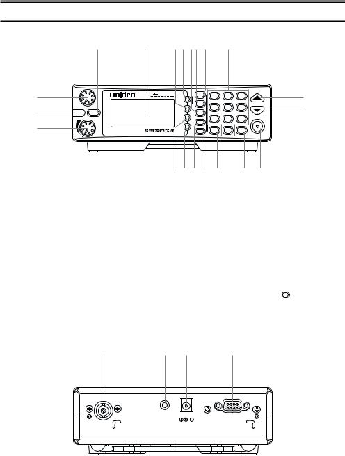
Front and Rear Views
4 |
5 |
6 7 8 9 10 |
11 |
1
2
3
|
|
|
1-50 |
51-100 |
101-150 |
|
|
|
HWY STATE |
1 |
2 |
3 |
12 |
|
DELAY |
|
||||
|
|
151-200 |
201-250 |
|
||
SQL |
push |
PVT |
4 |
5 |
6 |
|
|
FLASH |
|
13 |
|||
|
L/O |
|
||||
ALERT |
MUTE |
SVC |
|
|
|
|
|
DATA |
|
7 |
8 |
9 |
HOLD/RESUME |
|
|
SRCH |
|
|||
|
|
RMT |
|
M-LOCK |
|
|
|
PRI |
|
|
|
||
|
TRUNK . |
0 |
E |
|
||
|
BCT8 |
|
||||
|
push |
|
|
|
|
|
VOL |
ALERT |
|
|
|
|
|
|
141516 17 18 |
|
19 |
20 |
||
1. |
Squelch Control / Flash Brightness |
|
10. |
Highway Scanning / State Key (HWY, |
|
Selector (SQL, FLASH) |
|
|
STATE) |
2. |
Alerting Light (ALERT) |
|
11. |
Numeric Keypad |
3. |
Volume Control / Alert Tone Selector |
|
12. |
Up Key (▲) |
|
(VOL) |
|
13. |
Down Key (▼) |
4. |
Mute Key (MUTE) |
|
14. |
Data Key (DATA) |
5. |
Display |
|
15. |
Priority Key (PRI) |
6. |
Lockout Key (L/O) |
|
16. |
Search Key (SRCH) |
7. |
Delay Key (DELAY) |
|
17. |
Trunk Key (TRUNK) |
8. |
Service Key (SVC) |
|
18. |
Decimal/Remote Key ( . , RMT) |
9. |
Private Scanning Key (PVT) |
|
19. |
Enter / Memory Lock Key (E, M-LOCK) |
|
|
|
20. |
Hold/Resume Key (HOLD/RESUME) |
|
21 |
22 |
23 |
24 |
EXT. |
DC 12V |
REMOTE |
SP. |
|
|
ANT. |
|
|
21. |
Antenna Connector (ANT.) |
23. |
DC Power Jack (DC 12V) |
22. |
External Speaker Jack (EXT. SP.) |
24. |
Remote Control Terminal (REMOTE) |
2
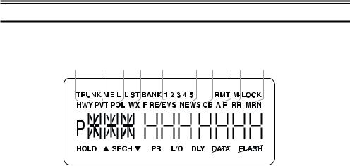
Icon Display
1 |
2 3 4 |
|
5 |
6 |
7 |
|
|
8 |
9 |
|
|
|||||||||||||||||||||
10 |
|
11 |
|
|
12 |
|
|
13 |
|
|
|
14 |
|
|
|
15 |
16 |
|
|
1718 |
|
19 |
||||||||||
|
|
|
|
|
|
|
|
|
|
|
|
|
|
|
|
|
|
|
|
|
|
|
|
|
|
|
|
|
|
|
|
|
|
|
|
|
|
|
|
|
|
|
|
|
|
|
|
|
|
|
|
|
|
|
|
|
|
|
|
|
|
|
|
|
|
|
|
|
|
|
|
|
|
|
|
|
|
|
|
|
|
|
|
|
|
|
|
|
|
|
|
|
|
|
|
|
|
|
|
|
|
|
|
|
|
|
|
|
|
|
|
|
|
|
|
|
|
|
|
|
|
|
|
|
|
|
|
|
|
|
|
|
|
|
|
|
|
|
|
|
|
|
|
|
|
|
|
|
|
|
|
|
|
|
|
|
|
|
|
|
|
|
|
|
28
|
|
|
|
|
|
|
|
|
|
|
|
|
|
|
|
|
|
|
|
|
|
|
|
|
|
|
|
|
|
|
|
|
|
|
|
|
|
|
|
|
|
|
|
|
|
|
|
|
|
|
|
|
|
|
|
|
|
|
|
|
|
|
|
|
|
|
|
|
|
|
|
|
|
|
|
|
|
|
|
|
|
|
|
|
|
|
|
|
|
|
|
|
|
|
|
|
|
|
|
|
|
|
|
|
|
|
|
|
|
|
|
|
|
|
|
|
|
|
|
|
|
|
|
|
|
|
|
|
|
|
|
|
|
|
20 |
21 |
22 |
21 |
23 |
24 |
|
25 |
26 |
27 |
|||||||||||||||||
1.Trunk Tracking mode (TRUNK)
2.Motorola trunking channel (M)
3.EDACS trunking channel (E)
4.LTR trunking channel (L)
5.Scan list (LIST)
6.Scan bank (BANK)
7.Bank’s number and ID’s list number (12345)
8.Remote control mode (RMT)
9.Memory locked (M-LOCK)
10.Highway Patrol scan mode (HWY)
11.Private bank scan mode (PVT)
12.Police scan mode (POL)
13.Weather scan mode (WX)
14.Fire and Emergency scan mode (FIRE/EMS)
15.News scan mode (NEWS)
16.Citizen Band scan mode (CB)
17.Aircraft band scan mode (AIR)
18.Railroad scan mode (RR)
19.Marine scan mode (MRN)
20.Scan hold and Search hold mode (HOLD)
21.Search direction (▲, ▼)
22.Band and ID search mode (SRCH)
23.Priority function option (PRI)
24.Lockout channel and talk group (L/O)
25.Delay option (DLY)
26.DATA Skip option (
 )
)
27.While Alert Light is off (

 )
)
28.Priority channel and talk group (P)
Uniden®, BearTracker® and Bearcat® are registered trademarks of Uniden America Corporation.
TrunkTracker is a proprietary trademark of Uniden America Corporation.
3

Terminology
What are Highway Patrol Alerts?
Most highway patrol vehicles on the road today are equipped with a secondary radio system known as a “mobile extender” or “vehicular repeater.” Whenever the dispatcher transmits to any vehicle in the district, “mobile extender” in every car within the district is activated.
Using a constant PRIORITY check of specific frequencies in each state, the BCT8 recognizes and alerts you to transmissions from “mobile extender” radios as well as from car-to-car, aircraft-to-car and other special-purpose frequencies. You receive an audible (beep tone) and visual (flashing Alert light) alert whenever you are within an approximate three-mile radius of Highway Patrol/ State Police units using a mobile extender unit.
What is Scanning?
Unlike standard AM or FM radio stations, most two-way communications do not transmit continuously. The BCT8 scans the Frequencies you have programmed into the Scanner’s channels until it finds an active frequency.
Scanning stops on an active frequency and remains on that channel as long as the transmission continues. When the transmission ends, the scanning cycle resumes until another transmission is received.
What is Searching?
The BCT8 can search each of its 13 bands to find active frequencies. This is different from scanning because you are searching for frequencies that have not been programmed into your Scanner’s channels. The scanner automatically chooses between two speeds while searching. During search mode the scanner will search 100 frequencies per second for band with 12.5 kHz steps and during Turbo SEARCH mode the scanner can achieve up to 300 frequencies per second for bands with 5 kHz steps.
What is Trunk Tracking?
Conventional scanning is a simple concept. You enter a radio frequency in your scanner’s memory which is used by someone you want to monitor. For example, the police in your area may broadcast on 460.500 MHz, the fire department on 154.445 MHz, the highway department on 37.900 MHz, etc. So when your scanner stops on a frequency, you usually know who it is, and more importantly, you can stop on a channel and listen to an entire conversation. This type of scanning is easy and fun.
As the demand for public communications has increased, many public radio users don't have enough frequencies to meet their needs, and this has created a serious problem. Trunking radio systems have been implemented to solve this problem.
4
In a trunked radio system the frequencies are shared among the police and fire departments and a computer systematically assigns available frequencies when they are needed for communications.
Sharing of the available public service frequencies, or trunking, allows cities, counties, or other agencies to accommodate hundreds of users with relatively few frequencies. Following a conversation on a trunked system using a scanner is difficult, if not impossible. Because when there's a short break during the conversation you're monitoring, it’s possible that the talkgroup will be assigned to a completely different frequency in the trunked system. This type of scanning is difficult and frustrating.
TrunkTracker Technology changes this! Not only does your new BCT8 scan channels like a conventional scanner, it actually follows the users of a trunked radio system. Once you know a talkgroups ID, you won’t miss any of the action.
If you're a new scanner enthusiast, you may want to read the first part of this manual and use your scanner in conventional mode before you begin trunk tracking. Understanding scanning fundamentals and its terminology will make trunk tracking much easier.
5

Feature Highlights
•Pre-programmed frequencies specific to each state (except Hawaii).
•Pre-programmed Trunked and conventional Highway Patrol frequencies
•Highway Patrol Priority Alert
-Receive audible and visual alert when within three miles of many Highway Patrol/State units
•Pre-programmed frequencies for the following categories: -Local Police and County Sheriffs
-Fire and Emergency Medical Service -News Media
-Weather (continuous NOAA weather and Canadian Coast Guard broadcasts) -CB Radio
-Aircraft -Railroads -Marine Band
-Department of Transportation
•Trunk Tracking – Follow VHF High Band UHF 800MHz trunked public safety and public service systems just as if conventional two-way communications were used.
•Multi-Track – Track more than one trunking system at a time. Scan conventional and trunked systems at the same time.
•250 Channels – Program one frequency into each channel. You must have at least one channel programmed to use the Scan mode.
•13 Bands – Includes 13 bands, with aircraft and 800 MHz.
•5 Banks – 5 banks with 50 channels each are useful for storing similar frequencies to maintain faster scanning cycles or for storing all the frequencies of a trunked system.
•25 MHz-956 MHz – Indicates the range of frequencies that can be searched within the bands of your scanner.
Note: The frequency coverage is not continuous and excludes the cellelar telephone Band.
•5 Priority Channels – You can assign one priority channel in each bank. Assigning a priority channel allows you to track activity on your most important channel(s) while monitoring other channels for transmissions. You can also assign trunking priority talkgroups.
•Data Skip – Allows your scanner to skip unwanted data transmissions and reduces birdies.
•Direct Channel Access – Go directly to any channel without entering programming mode.
•Turbo Search – Increases the search speed to 300 steps per second. This applies only to transmission bands with 5 kHz steps.
•PC Programmable – Allows you to easily program all frequencies and Trunking Talk Groups into your BCT8 through Uniden BCT8 Scanning software running on your PC.
–For more information on BCT8 SS Programming software visit our website at scanner.uniden.com.
6
Where to Obtain More Information
Before you can scan the PRIVATE bank, you must program frequencies into the scanner’s channels. The Frequency Guide lists typical frequencies used around the U.S.A. and Canada that you may program into your new scanner. However, this is not a complete list of frequencies for your area.
To obtain frequency information for your area, contact one of the following:
•Scanner Master
1 (800) Scanner (7226634) (Hours are from 10:00 a.m. to 5:00 p.m. Eastern Time Monday through Friday.) frequenciew@scannermaster.co
To obtain another copy of the frequency guide, contact one of the following:
•Uniden Parts Department
(800) 554-3988 (Hours are from 8:00 a.m. to 5:00 p.m. Central Time Monday through Friday.)
•Local Dealer
Information on the Internet
If you have access to the internet, you may want to visit one of the following websites for additional information:
scanner.uniden.com
www.bearcat1.com
7

Included with Your Scanner Package
•BCT8 Scanner
•AC Adapter (AD 140U)
•DC Power Cord
•Cigarette Lighter Adapter Plug (Model CD007)
•Telescopic Antenna (Model AT129)
•Window Mount Antenna (Model AT002)
•Operating Guide
•Trunk Tracker Frequency Guide
•Other Printed Materials
•Remote Programming Software CD-ROM
•Mobile Mounting Bracket (Model MB-008)
If any of these items are missing or damaged, immediately contact your place of purchase or Uniden Customer Service at: (800) 297-1023, 8:00 a.m. to 5:00 p.m., Central Time, Monday through Friday.
Optional Accessories
The following optional accessories for your BCT8 are available from your local Uniden Dealer or through the Uniden Parts Department by calling: (800) 554-3988, 8:00 AM to 5:00 PM CST, Monday through Friday. We can also be reached on the web at www.uniden.com.
DC Power Cord (Model PS-001) - For hard wiring power from your car to your scanner.
Motorola Antenna Adapter (Model PLG-134) - Use only if your antenna has a Motorolatype plug.
8

Installing the BCT8
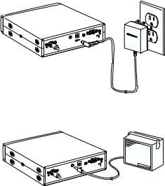
For Home Use (Desktop Installation)
1.Insert the DC plug end of the AC Adapter into the DC 12V jack on the rear panel.
2.Plug the AC Adapter into a standard 120V AC wall outlet.
3.Plug the Telescoping Antenna into the ANT connector.
Extend the antenna to its full height. For frequencies higher than 406 MHz, shortening the antenna may improve the reception.
4.Use the desktop stand for a better viewing and operating angle.
Helpful Hints
•If strong interference or electrical noise is received, relocate the scanner or its antenna away from the source.
•If you are operating the scanner in a fringe area or need to improve reception, use an optional antenna designed for multi-band coverage. (You can purchase this type of antenna at a local electronics store.)
•If the optional antenna has no cable, use 50-70 ohm coaxial cable for lead-in. A mating plug may be necessary for the optional antennas.
For Mobile Use (In-Car Installation)
Installation for Temporary Use:
A Cigarette Lighter Power Cord is provided for easy, temporary installation.
Warning: Do not use the cigarette lighter power cord in a positive ground vehicle.
Plug one end of the Cigarette Lighter Power Cord into the cigarette lighter jack and the other end into the DC 12V jack on the back of the scanner.
Connecting the Antenna Plug
Connect the mobile antenna plug into the ANT connector on the rear panel. (For more information on antenna installation, please refer to the instruction guide that came with your antenna.)
The BCT8 can be mounted using the supplied mounting bracket.
1.Select an ideal location in your vehicle to mount the BCT8. Avoid a location that could interfere with your driving. In a passenger car, the ideal location is underneath the dashboard on the passenger side.
2.Use the supplied mounting bracket as a template for marking the location of the mounting screws. Note: If there are screws already holding the dashboard, you can use the same screw holes to mount the bracket.
9
3.Drill the necessary holes and secure the mounting bracket in place using the screws provided.
4.Mount the radio to the bracket only after the wiring has been connected to the rear panel.
Connecting the Power Cord
Note: If you are not experienced in connecting accessories to the vehicle fuse box, please see your automotive dealer for advice on proper installation.
Installation for everyday use:
1.Check the vehicle battery connections to determine which battery terminal (positive or negative) is grounded to the engine block or chassis. Most of today’s vehicles use a negative ground. If your vehicle has a negative ground, follow Steps 2 and 3. Otherwise, skip to the note following Step 3.
2.Connect the RED wire of the DC power cord to the accessory contact in your vehicle’s +12V DC fuse box.
3.Connect the BLACK wire of the DC power cord to the negative side of the vehicle (usually the chassis).
Note: In vehicles with a positive ground, the RED wire connects to the chassis and the BLACK wire connects to the accessory contact in the fuse box.
4. Insert the DC plug into the DC 12V jack on the back of the scanner.
10
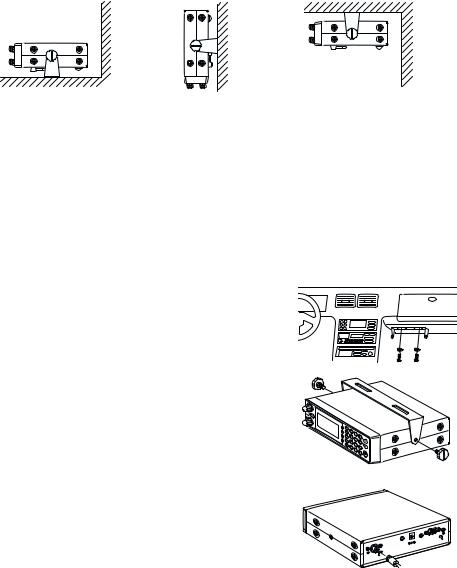
Typical Mounting Methods
The BCT8 can be conveniently mounted on a table, bulkhead, overhead, or any other desired location with the supplied mounting bracket (MB008) (refer to figure below for typical mounting methods).
Caution: Make sure there are no hidden electrical wires or other items behind the desired location before proceeding. Check that free access for mounting and cabling
is available.
• Table top mount |
• Bulkhead mount |
• Overhead mount |
Mounting the Scanner in Your Vehicle
Before you mount the scanner, make sure you have all the necessary materials. Then confirm that the scanner fits your vehicle’s mounting area. This unit requires a mounting area of 2.44 inch high by 7.06 inch wide by 6.10 inch deep (50.8 x 176.5 x 152.5 mm).
Caution: Be sure to avoid obstructions behind the mounting surface.
Follow these steps to mount the scanner in your vehicle.
1.Choose a mounting location, then use the supplied mounting bracket as a template to mark the positions for
the mounting screw holes.
2. In the marked positions, drill holes slightly smaller than the supplied screws.
3. Attach the mounting bracket to the mounting location using the supplied screws and lock washers.
4.Attach the scanner to the mounting bracket using the supplied mounting knobs.
5.Connect the antenna’s cable to the ANT. connector on the rear of the scanner.
 SQL
SQL
 VOL
VOL
Note: If the antenna cable’s connector does not fit in the ANT. connector, you might also need a Motorola-to BNC antenna plug adapter (available at a local
electronics store).
REMOTE
DC 12V
EXT.
SP.
ANT.
11
Applying Power for Vehicle Installation
You can power your scanner using the supplied DC cigarette lighter power cord or an DC power cord.
DC power Installation
To power the scanner from a vehicle’s 12V power source (such as a cigarette-lighter socket), you need a cigarette-lighter adapter.
To connect an DC cigarette-lighter power cable, insert its barrel plug into the
DC 12V jack on the rear of the scanner, then plug the power cable into your vehicle’s cigarette lighter socket.
Note: If you use a cigarette-lighter power cable and your vehicle’s engine is running, you might hear electrical noise from the engine while scanning. This is normal.
Caution: DC 12 V Jack can use a power source that supplies 12V DC at least 500 mA. You must use a power source that supplies 12V DC and delivers at least
500 mA. Your standard 12V car battery should be sufficient. The cord connector’s center tip must be set to positive and its plug must fit the scanner’s DC 12V jack. The supplied DC power cord meets these specifications. Using a power cord that does not meet these specifications could damage the scanner or the adapter.
•Always connect the adapter or DC power cord to the scanner before you connect it to the power source. When you finish, disconnect the adapter or DC power cord from the power source before you disconnect it from the scanner.
•For added safety and to protect your scanner,
disconnect the cable from your vehicle battery’s negative (-) terminal before you begin.
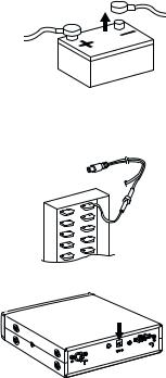
Follow these steps to connect the DC power cord.
1.Connect the power cord’s black wire to a chassis ground, such as a metal screw attached to a metal part of the vehicle’s frame. Be sure that the screw is not insulated from the frame by a plastic part.
2. Connect the power cord’s red wire (with in-line fuse) to a source of voltage that turns on and off with the ignition switch, such as a spare accessory terminal in your vehicle’s fuse box.
3. Insert the power cord’s barrel plug into the DC 12V jack on the rear of the scanner.
4. Reconnect the cable to the vehicle battery’s negative (-) terminal.
REMOTE
DC 12V
EXT.
SP.
ANT.
12
Applying Power Using Standard AC Power
To power the scanner from an AC outlet, use the provided AC adapter with a 5.5 mm outer diameter/2.1mm inner diameter tip.
Caution: You must use a Class 2 power source that supplies 12V DC and delivers at least 500 mA. The cord connector’s center tip must be set to positive and its plug must fit the scanner’s DC 12V jack. Using an adapter that does not meet these specifications could damage the scanner or the adapter.
•Always connect the AC adapter to the scanner before you connect it to AC power. When you finish, disconnect the adapter from the AC power before you disconnect it from
the scanner.
1.Insert the adapter’s barrel plug into the DC 12V jack on the rear of the scanner.
2.Plug the adapter into a standard AC outlet.
Note: Use only the AC adapter supplied with your scanner.
REMOTE
DC 12V
EXT.
SP.
ANT.
12V
Connecting an External Speaker
In a noisy area, an external speaker (available at a local electronics store) positioned in the right place might provide more comfortable listening.
Plug the speaker cable’s 1/8 inch (3.5 mm) plug into your scanner’s EXT. SP. jack.
Note: Connecting an external speaker disconnects the scanner’s internal speaker.
REMOTE
DC 12V
EXT.
SP.
ANT.
Listening Safely
•Do not use the earphone. The volume is not adjustable for the Warning Alert and damage to your hearing could occur.
Connecting the Clone Cable
You can transfer the programmed data to and from another BCT8 scanner using a RS232C Straight Cable (9 pin to 9 pin) (not supplied). Connect the cable between each scanner’s REMOTE jacks. See "Clone Mode" on page 49. You can also upload or download the programmed data to or from a PC using optional programming software available through your local electronics store.
13
Scanning Overview
You can scan in one of four ways:
1.Highway Patrol Scanning When you select a state you want to scan in Highway Patrol mode, you can scan pre-programmed Highway Patrol frequencies.
2.Service Scanning Press SVC to select one of the nine services to find an active frequency.
3.Band Search Select a frequency band to search. The Search function is different from scanning. It searches for any active frequency step by step within the lower and upper limits of the band. When an active frequency is found, the scanner will stop and stay on that frequency as long as that transmission lasts. If that frequency is interesting to you, press HOLD/RESUME to hold the frequency on the display. Then program it into the private bank you want to store. If you do not want to program that frequency, press HOLD/RESUME or just wait until the transmission ends. The search resumes automatically 2 seconds after the last transmission and looks for more active frequencies.
4.Private Scanning If you have programmed frequencies into this bank, press PVT to scan only those that you have programmed in this bank.
Note: Before you can scan the Private Bank, you must program frequencies into the channels. To program frequencies, see “Programming Frequencies into Channels” on page 21.
When scanning stops on an active frequency, it remains on that channel as long as the transmission continues. When the transmission ends, the scanner will remain on the same channel for 2 more seconds, waiting for a responding transmission. If there is no responding transmission within 2 seconds, the scanning cycle resumes.
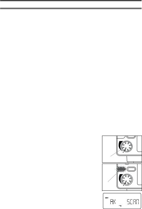
Turn the Scanner On
1. Turn the VOL knob clockwise.
The scanner is turned on: the Alert Light flashes and the Alert Tone beeps loudly.
Note: The Alert Tone depends on the currently setting selected (see page 17).
2. The last setting mode selected before starts.
ALERT |
MUTE |
|
push |
VOL |
ALERT |
Turn |
|
|
FLASH |
ALERT  MUTE
MUTE
Alert |
push |
|
|
VOL |
ALERT |
Light |
|
14
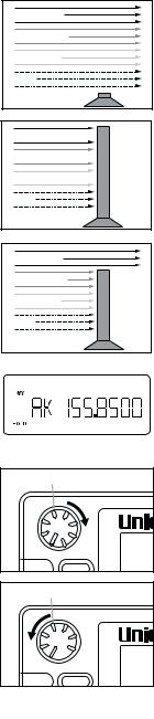
How Squelch Works
Think of “SQUELCH” as a gate. If the gate is too low (squelch too low), everything (all noise as well as signals) gets through.
If the gate is set too high (squelch too high), nothing gets through.
If the gate is set just right (squelch set properly), just the desired signals get through.
Setting the Squelch
1.To set the squelch, press HOLD/RESUME to stop scanning. If needed, adjust VOL until you do not hear a signal (see page 17).
2.Turn SQL fully clockwise until hiss heard.
This lowers the “squelch gate,” allowing all signals and noise to get through.
3.Turn SQL fully counterclockwise just until hiss stops.
This raises the “squelch gate,” allowing only strong signals to get through.
In the city, you may want to adjust the Squelch even further counterclockwise to decrease the range of the Highway Warning Alert signal.
This prevents the alert from sounding unnecessarily due to farther, less important sources.
Strong Signals |
Medium Signals |
Weak Signals |
Noise |
Strong Signals 
Medium Signals 
Weak Signals 
Noise
Strong Signals |
Medium Signals |
Weak Signals |
Noise |
Turn |
|
|
SQL |
push |
|
FLASH |
||
|
||
ALERT |
MUTE |
|
Turn |
|
SQL 
 push
push
FLASH
ALERT MUTE
15
Highway Patrol Scanning
Highway Patrol frequencies are pre-programmed on a state-by-state basis. When Highway Patrol scanning, the Highway Warning Alert is activated.
Selecting the State
1.Press STATE to select the state you are operating in. Press and hold STATE to scroll rapidly.
Hint: For the State Code Order, please see page 56.
2.To step forward through the states (A - W), press STATE and, within three seconds, press the ▲ key repeatedly. To
step backward through the states (W - A), press STATE and, within three seconds, press the ▼ key repeatedly.
3. To scroll rapidly, press and hold the ▲ or ▼ key.
Scanning Highway Patrol Frequency
You can scan Highway Patrol frequencies by pressing PVT or HWY.
1. Press HWY to scan through only pre-programmed Highway Patrol frequencies.
or
Press PVT repeatedly in Highway scanning mode until “HWY” appears on the display to scan through pre-programmed Highway Patrol frequencies.
Hint: If you press PVT repeatedly in Highway scanning mode until “HWY” and “PVT” appears on the display, you can mix-scan between Highway Patrol frequencies and User Programmed channels.
2. When the scanner receives communications, scanning stops, the state code and the frequency appear.
When the transmission ends, the scanner holds for two seconds on that frequency for a response. For more information on the Delay feature, please see page 28. If there is no response, scanning resumes.
16
Highway Patrol Scan Hold
1. When scanning stops on a desired frequency, press HOLD/RESUME to hold on that frequency as long as you like. When in the HOLD mode, press the ▲ or ▼ key to step up or down the frequency. To step up or down rapidly, press and hold the ▲ or ▼ key.
If you change into a frequency which is a control channel, the scanner may display the Active ID (When TRUNK mode is active).
2. To resume scanning, press HOLD/RESUME.
Note: Highway Warning Alert does not work while in the HOLD mode.
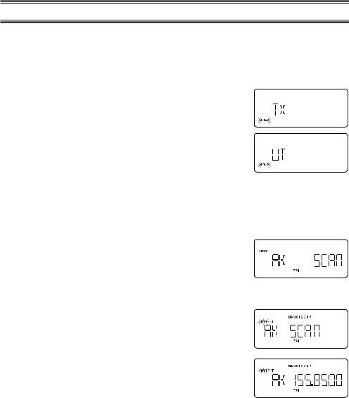
Highway Warning Alert
The scanner alerts you when Highway Patrol/State Police units using mobile extenders are within an approximate three mile radius.
1. |
The ALERT Light flashes and the Alert Tone beeps twice |
|
|
FLASH |
|
ALERT |
MUTE |
||
|
when a signal is received. |
|
|
|
2. |
The ALERT Light glows steadily for approximately three |
Alert |
|
|
|
minutes. Then, if no other mobile extender transmissions are |
|
push |
|
|
Light |
|
||
|
received, the light goes out. |
VOL |
ALERT |
|
|
Flashes |
|
|
|
|
|
|
|
3. If more transmissions are received before three minutes have passed, the ALERT Light flashes and the Alert Tone beeps once.
Alert Tone Volume
Push VOL to select Loud, Medium, or Soft.
The Alert Tone beeps and the ALERT Light flashes to your choice.
Muting the Alert Tone
Temporary Mute
Press MUTE during the Highway Warning Alert. The Alert Tone stops and the MUTE LED flashes until the alarm cycle (three minutes) is finished.
Continuous Mute
ALERT |
MUTE |
|
push |
VOL |
ALERT |
Push In |
|
|
FLASH |
ALERT  MUTE
MUTE
MUTE LED VOL |
push |
ALERT |
|
Flashes |
|
Press and hold MUTE for two seconds to turn Continuous Mute on whenever you wish. You hear two beeps and the MUTE LED lights continuously. No Alert Tones will beep.
Canceling Mute
To cancel Mute,
17
 Loading...