


Service and Parts Manual
Supplement
For Models
• 2075DWRR • CO2075DWR • 2075DWRWC
U-Line Corporation |
U-Line Corporation |
8900 North 55th Street |
PO Box 245040 |
Milwaukee, WI 53223 |
Milwaukee, WI 53224-9540 |
www.U-LineService.com
Phone (414) 354-0300 • FAX (414) 354-7905
Service & Parts Tech Lines Phone (800) 779-2547 • FAX (414) 354-5696
M
A
D
E
I
N
T
H
E
U
S
A
Design ■ Features ■ Performance
INTRODUCTION
General Information
2075DWRR
2075DWRWC
CO2075DWR
1
Design ■ Features ■ Performance
NOTES
2

Design ■ Features ■ Performance
INTRODUCTION
INTRODUCTION
Three generations of pride and quality manufacturing and design improvements are built into all U-Line products. The result: U-Line leads the market with innovative technology and superior craftsmanship.
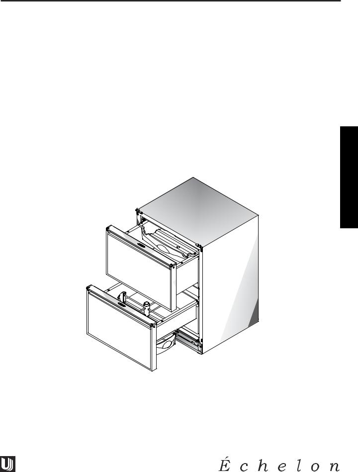
This manual contains specific instructions for servicing the U-Line Échelon 2075DWRR, CO2075DWR and 2075DWRWC.
Potential Problems With HFC-134A
This Service Manual has been written to cover product manufactured with HFC-134a. HFC-134A compressors will be received with a synthetic based ester oil charge. The hygroscopic (water attraction) property of ester oil is many times greater than that of the mineral oils previously used with CFC-12. High system moisture causes the formation of acids and alcohol which can damage the compressor. Systems should not be left open for more than fifteen (15) minutes at any time as humidity from the air will enter system. To assure system dehydration, the system should be pulled down to 100 microns and vacuum pump oil (mineral oil) must not be allowed to enter the system.
Cleanliness of the system will be extremely important. The presence of residues (chlorinated or greasy residues, mineral oil, or impurities) can lead to capillary tube restrictions, oil return problems and compressor damage. Flux must not be used on brazed joints.
3

INTRODUCTION
Design ■ Features ■ Performance
SERIAL NUMBER FORMAT
The serial number is divided into four segments. A typical serial number is 031234-01-5678. The first two digits of the first segment, 03, represent the year the unit was made.
The next four digits, 1234, represent the shop order number. Every model is assigned a new shop order number at the beginning of a production run.
The second two digit segment, 01, represents the month the unit was made.
The last four digits, 5678, are an internal control number used at U-Line Corporation.
031234-01-5678
Year Shop Month |
Factory Internal |
Order |
Control Number |
Number |
|
4
General
Information
GENERAL INFORMATION
Design ■ Features ■ Performance

Design ■ Features ■ Performance
GENERAL INFORMATION
LIMITED WARRANTY
U-Line Corporation warrants each U-Line product to be free from defects in materials and workmanship for a period of one year from the date of purchase; and warrants the sealed system (consisting of the compressor, the condenser, the evaporator, the hot gas bypass valve, the dryer and the connecting tubing) in each U-Line product to be free from defects in materials and workmanship for a period of five years from the date of purchase. During the initial one-year warranty period for all U-Line products U-Line shall: (1) at U-Line’s option, repair any product or replace any part of a product that breaches this warranty; and (2) for all Marine, RV and Domestic U-Line products sold and serviced in the United States (including Alaska and Hawaii) and Canada, U-Line shall cover the labor costs incurred in connection with the replacement of any defective part. During years two through five of the warranty period for the sealed system, U-Line shall: (1) repair or replace any part of the sealed system that breaches this warranty; and (2) for all Marine, RV and Domestic U-Line products sold and serviced in the United States (including Alaska and Hawaii) and Canada, U-Line shall cover the labor costs incurred in connection with the replacement of any defective part of the sealed system. All other charges, including transportation charges for replacements under this warranty and labor costs not specifically covered by this warranty, shall be borne by you. This warranty is extended only to the original purchaser of the U-Line product. The Registration Card included with the product should be promptly completed by you and mailed back to U-Line, or you can register on-line at www.U-LineService.com.
The following are excluded from this limited warranty: installation charges; damages caused by disasters or acts of God, such as fire, floods, wind and lightening; damages incurred or resulting from shipping, improper installation, unauthorized modification, or misuse/abuse of the product; customer education calls; food loss/spoilage; door and water level adjustments (except during the first 90 days from the date of purchase); defrosting the product; adjusting the controls; door reversal; or cleaning the condenser.
If a product defect is discovered during the applicable warranty period, you must promptly notify either the dealer from whom you purchased the product or U-Line at P.O. Box 23220, Milwaukee, Wisconsin 53223 or at 414-354-0300. In no event shall such notification be received later than 30 days after the expiration of the applicable warranty period. U-Line may require that defective parts be returned, at your expense, to U-Line’s factory in Milwaukee, Wisconsin, for inspection. Any action by you for breach of warranty must be commenced within one year after the expiration of the applicable warranty period.
This limited warranty is in lieu of any other warranty, express or implied, including, but not limited to any implied warranty of merchantability or fitness for a particular purpose; provided however, that to the extent required by law, implied warranties are included but do not extend beyond the duration of the express warranty first set forth above. U-Line’s sole liability and your exclusive remedy under this warranty is set forth in the initial paragraph above. U-Line shall have no liability whatsoever for any incidental, consequential or special damages arising from the sale, use or installation of the product or from any other cause whatsoever, whether based on warranty (express or implied) or otherwise based on contract, tort or any other theory of liability.
Some states do not allow limitations on how long an implied warranty lasts or the exclusion or limitation of incidental or consequential damages, so the above limitations may not apply to you. This warranty gives you specific legal rights, and you may also have other rights which vary from state to state.
5

GENERAL INFORMATION
Design ■ Features ■ Performance
WARRANTY CLAIMS PROCEDURE
When submitting claims for warranty payment, please follow these guidelines.
You can use any form you would normally use to bill your customer (your own computer generated form, Narda, USA, etc.).
The model and serial number MUST be on the claims. Claims will not be paid without a model and serial number.
If you work on more than one unit per service call please submit a separate claim for each unit.
We track all defects through warranty claims, so please be specific on what the repair was. If it is a system leak, please specify where the leak was.
Please be sure the claim is legible. If the claim form cannot be read, it will be returned, unpaid.
U-Line will not cover part or labor claims for the replacement of a complete ice maker assembly. All ice maker parts are available as replacement parts and are stocked in our inventory. Remember: we do not pay customer education calls. Door and water level adjustments are 90 day warranties only.
If you are changing out a unit please supply the model and serial number of both units (the unit being replaced and the new unit) and the R.A. number.
If a copy of the Proof of Purchase/Install is not available at the site, the technician should record the following information on the Labor Invoice:
•The name of the selling Dealer
•The date of purchase/installation
•The Order or Invoice number (if available)
•The type of document they saw i.e. Store Receipt, Closing Papers, Sign-Off of Building Permit, Final Walk Through, etc.
At U-Line, parts and labor claims are paid separately. Included in labor are freon and recovery charges, all other parts are handled by the parts department. We require that some parts be returned to us, so we may return them to our vendor. It will be noted on your packing list if we require you to return the part. If a part is to be returned please include a copy of the packing list and a copy of your claim. If the part was purchased at one of our part distributors, you must handle the part warranty with that company. For labor payment please send a readable copy of your claim to U-Line Corporation, P.O. Box 245040, Milwaukee WI, 53224-9540, for warranty payment, or fax a legible copy to 414-354-5696.
6
Design ■ Features ■ Performance
GENERAL INFORMATION
PARTS LISTING
How to Order Replacement Parts
1.Locate the illustration(s) for the model you are servicing.
2.Refer to the area where the desired part would be installed, locate the part and note the item number assigned to it.
3.Locate the item number in the left column of the parts listing which is on the next page from the product illustration. Note the full description and the corresponding part number. If this is for a warranty unit, please indicate and record the model and serial numbers.
4.When ordering parts, it will be necessary to supply us with Model Number, Serial Number, Part Number, Part Description and in some cases Color or Voltage.
5.U-Line requires the return of the parts listed below if replaced under warranty.
•Fan motors (condenser and evaporator)
•Temperature controls
•Water solenoid valves
•Pumps
•Control boards (with thermistors)
•Ice maker motors
•Bypass solenoids
•Compressors (two years old or less - lines soldered closed)
All warranty parts will be shipped at no charge as long as warranty status has been confirmed. We require that some parts be returned to us, so we may return them to our vendor. It will be noted on your packing list if we require you to return a part or if you may field scrap it. If U-Line requires a defective part to be returned, a prepaid shipping label will be included with your new replacement part. When returning parts please enclose a copy of your packing list and a copy of your labor claim, showing the model and serial number, and tag or label the part with the nature of the defect.
Our warranty records may not match the customer’s information. In this case a proof of purchase will be required. If you do not have the proof of purchase at the time the order is placed, the part will be sent net 15 days (COD if you don’t have an open account with U-Line Corporation). When the proof of purchase is provided we will credit your account (a check will be sent if the part was sent COD).
6. Parts may be ordered on-line or by FAX or phone.
On-Line: www.U-LineService.com
FAX Number: (414) 354-7905
Phone Number: (414) 354-0300 or (414) 354-7885; press 3
To expedite parts shipments, on-line ordering is fastest. When placing FAX orders, copy the FAX Parts Order Form, located in the back of this manual, when placing an order, or order on-line at www.u-lineservice.com.
7.Effective immediately, U-Line will not pay warranty claims for the replacement of a complete ice maker assembly. Complete ice maker assembly replacement is not necessary because all ice maker parts are available as replacement parts and are stocked in our inventory.
REPLACEMENT PARTS: Use only genuine U-Line replacement parts. The use of non-U-Line parts can reduce ice rate, cause water to overflow from ice maker mold, damage the unit, and may void the warranty.
7
GENERAL INFORMATION
Design ■ Features ■ Performance
SAFETY PRECAUTIONS
Do not attempt to service or repair the unit until you have read the entire procedure. Safety items throughout this manual are labeled with Warning or Caution.
! WARNING !
Warning means that failure to follow this safety statement may result in extensive product damage, serious personal injury, or death.
!
Caution means that failure to follow this safety statement may result in minor or moderate personal injury, property or equipment damage.
! WARNING !
DANGER: Risk of child entrapment. Before you throw away an old refrigerator or freezer: Take off the doors, leave shelves in place so that children may not easily climb inside.
!WARNING !
•Never attempt to repair or perform maintenance on the unit until the electricity has been disconnected.
•Altering, cutting of power cord, removal of power cord, removal of power plug, or direct wiring can cause serious injury, fire and/or loss of property and/or life and will void the warranty.
!


•Do not lift unit by door handle.
•Never use an ice pick or other sharp instrument to help speed up defrosting. These instruments can puncture the inner lining or damage the cooling unit.
•Failure to clean the condenser every three months can cause the unit to malfunction. This could void the warranty.
•Never install the unit behind closed doors. Be sure front grille is free of obstruction. Obstructing free air flow can cause the unit to malfunction, and may void the warranty.
8
2075DWRR

2075DWRR |
Design ■ Features ■ Performance |
|
|
|
|
|
|
|
Design ■ Features ■ Performance |
2075DWRR |
COMPRESSOR/ELECTRICAL SPECIFICATIONS
2075DWRR
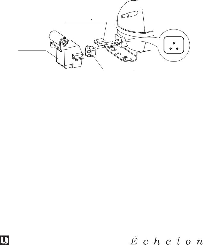
EMU30HSC
OVERLOAD PROTECTOR
|
|
C |
RELAY COVER |
S |
R |
|
STARTING RELAY
UL183-3C
COMPRESSOR PINS
To measure start winding resistance, measure across the C-S pins.
To measure run winding resistance, measure across the C-R pins. These pins should never measure any resistance to ground. This would indicate a shorted compressor.
Specifications |
|
|
EMU30HSC Start Winding Resistance: |
28 OHMS |
|
EMU30HSC Run Winding Resistance: |
8 OHMS |
|
115 |
VOLT Capacitor: |
12 µF |
115 |
VOLT Valve Coil Resistance: |
380 OHMS |
115 |
VOLT Drain Pan Heater |
6900 OHMS |
9
2075DWRR |
Design ■ Features ■ Performance |
REFRIGERATION SYSTEMS
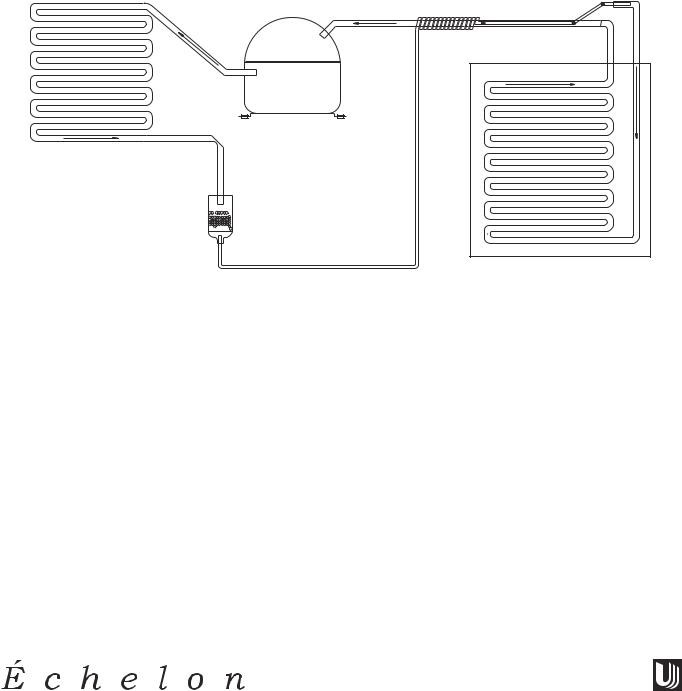
Normal Vapor/Compression Cycle Refrigeration
•Refrigerant is pumped from the compressor to the condenser as a high pressure, high temperature vapor.
•As the refrigerant cools in the high pressure condenser, the vapor condenses to liquid. During this phase change, a great amount of heat is rejected with the help of the condenser fan.
•The liquid then flows to the dryer where it is strained and filtered.
COMPRESSOR
CONDENSER
DRYER 
EVAPORATOR
CAPILLARY TUBE
UL183-1
•From the dryer, the refrigerant flows through the capillary tube which meters the liquid refrigerant to the evaporator. The pressure of the refrigerant is reduced to the evaporating or low side pressure.
•The reduction of pressure on the liquid refrigerant causes it to boil or vaporize until it reaches saturation temperature. As the low temperature refrigerant passes through the evaporator coil, it continues to absorb a lot of heat, causing the boiling action to continue until the refrigerant is completely vaporized. It is during this phase change that the most heat is absorbed (the cooling takes place) in the refrigerator.
•The refrigerant vapor leaving the evaporator travels through the suction line to the compressor inlet. The compressor takes the low pressure vapor and compresses it, increasing both pressure and temperature. The hot high pressure gas is pumped out the discharge line and into the condenser. The cycle continues.
10

Design ■ Features ■ Performance |
2075DWRR |
THERMISTOR
The thermistor senses the compartment temperature. This is used in conjunction with the control board to determine the length of the refrigeration cycle.
Thermistors generally fail due to moisture or physical damage.
SERVICE NOTES
2075DWRR
The 2075DWRR has the same basic refrigeration system as the 2075R with a few exceptions.
•The compressor is a high efficiency Embraco EMU30HSC.
•The electro-mechanical gas bulb is replaced with an electronic controller. The controller features a digital temperature display and control with two LED indicators and three touch pad buttons.
•The mullion between the two drawers has a low wattage “anti sweat” surface heater to prevent condensation on the mullion. Additionally, there is an anti-frost heater on the drain trough.
A thermal cut-out is mounted on the base, where the thermostat is normally mounted. This energy saving feature cuts-out the “anti-sweat” heater as well as the trough heater in high ambient temperatures, when in most conditions, the mullion would normally be warmed by ambient air.
•There are two interior lights and light switches. The switches are mounted in a switch box in the rear interior of the cabinet and the lights, in a housing in the top front of the drawers.
11

2075DWRR |
Design ■ Features ■ Performance |
THE ELECTRONIC TEMPERATURE CONTROLLERS
2075DWRR
•The controller has a four minute minimum off-cycle regardless of the thermistor status.
•The controller has a 4° differential built into it for the refrigerator thermistor. When it senses 38°F, the refrigerator will cool until the thermistor senses 36°F, and will not re-initiate cooling until the thermistor senses 40°F. When monitoring actual temperature, by pressing WARMER temporarily, the refrigeration cycle may be off, when the temperature is a degree warmer than the set point, or the refrigeration cycle on, when it is a degree below the set point.
•The LED status indicator lights indicate compartment temperature is displayed and open thermistor. A solid light on, in LED position (1), means compartment temperature is displayed. A flashing light, in LED position (2), means open thermistor. (The thermistor has failed or has been out of limits.) If a refrigerator thermistor fails, the refrigerator will shut down. A thermistor would normally fail by opening (no continuity), or by shorting (no resistance).
•Under most conditions, the refrigerator will remain frost-free by clearing itself between refrigeration cycles. Because there is no thermostat bulb on the evaporator, like other U-Line refrigerators, the controller runs a 45 minute off-cycle for every 12 hours of clock time. The refrigerator will not cool during this off-cycle even if the refrigerator thermistor is calling for cooling.
•The entire control system is mounted in a single housing in the top drawer.
12
Design ■ Features ■ Performance |
2075DWRR |
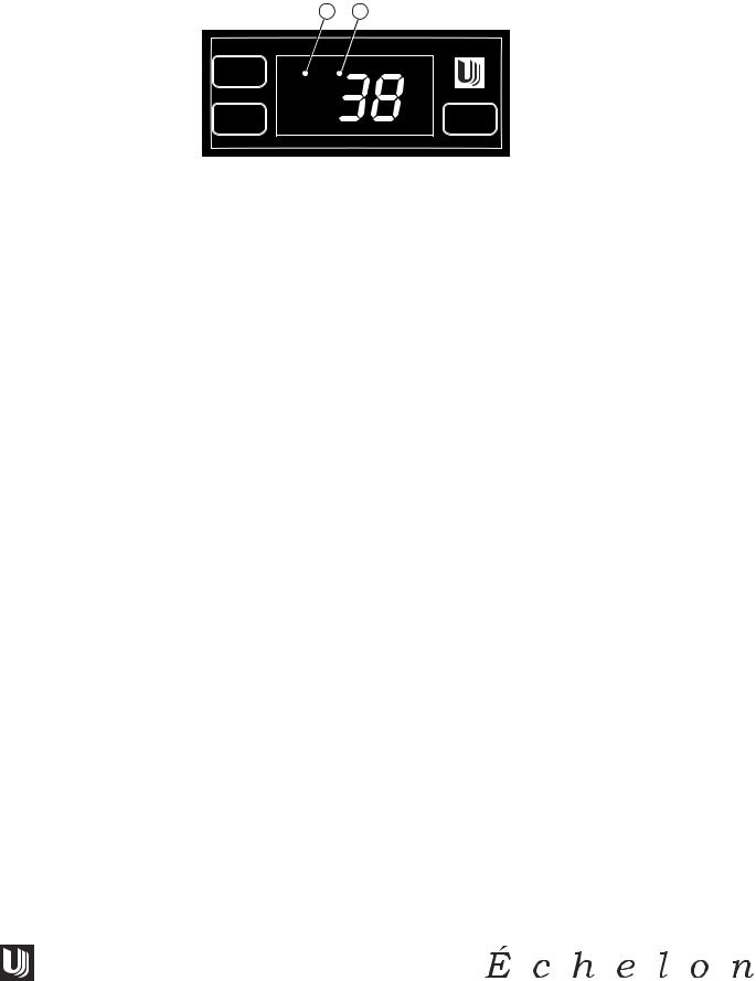
2075DWRR
1 2
WARMER
COOLER
SET
TEMP
CLRCO011B
The temperature controller is located in the top drawer. The LED display shows the temperature set point and is calibrated in degrees Fahrenheit. The controller is factory programmed for a set point of 38°F which will show when the unit is first powered-up.
To display actual temperature, press the “WARMER” button momentarily. A solid status indicator light (1) will show the air temperature reading in the cabinet for approximately 10 seconds.
To adjust the temperature set point, press the “SET TEMP” button momentarily; the display will flash. Press the “WARMER” or “COOLER” button as desired to change the set point. When the desired set point shows on the display, wait 10 seconds and the new set point will be saved. Wait 24 hours for the temperature to stabilize before checking the actual temperature again. The temperature range is 34°F to 45°F.
Indicator light status
LED |
|
Status |
|
Indicates |
1 |
• Solid |
• Compartment temperature displayed |
||
|
• |
Flashing |
• |
Not Applicable |
2 |
• |
Flashing |
• |
Open Thermistor |
|
|
|
|
|
13
REFRIGERATION SYSTEM DIAGNOSIS GUIDE
|
|
SystemSuction |
Suction |
Compressor |
Condenser |
Capillary |
Evaporator |
Wattage |
|
|
|
Condition |
Pressure |
Line |
Discharge |
|
Tube |
|
|
|
|
|
|
|
|
|
|
|
|
|
|
Normal |
Normal |
Slightly below |
Very hot |
Very hot |
Warm |
Cold |
Normal |
|
|
|
|
room |
|
|
|
|
|
|
|
|
|
temperature |
|
|
|
|
|
|
|
|
|
|
|
|
|
|
|
|
|
Overcharge |
Higher than |
Very cold |
Slightly warm |
Hot to warm |
Cool |
Cold |
Higher than |
|
|
|
normal |
may frost |
to hot |
|
|
|
normal |
|
|
|
|
heavily |
|
|
|
|
|
|
|
|
|
|
|
|
|
|
|
|
|
Undercharge |
Lower than |
Warm - near |
Hot |
Warm |
Warm |
Extremely cold |
Lower than |
|
|
|
normal |
room |
|
|
|
near inlet - |
normal |
|
|
|
|
temperature |
|
|
|
outlet |
|
14 |
|
|
|
|
|
|
|
below room |
|
|
|
|
|
|
|
|
temperature |
|
|
|
|
|
|
|
|
|
|
|
|
|
|
Partial |
Somewhat |
Warm - near |
Very hot |
Top passes |
Room |
Extremely cold |
Lower than |
|
|
Restriction |
lower than |
room |
|
warm - |
temperature |
near inlet - |
normal |
|
|
|
normal-in |
temperature |
|
lower passes |
(cool) or |
outlet |
|
|
|
|
vacuum |
|
|
cool |
colder |
below room |
|
|
|
|
|
|
|
(near room |
|
temperature |
|
|
|
|
|
|
|
temperature) |
|
backing up |
|
|
|
|
|
|
|
due to liquid |
|
|
|
|
|
|
|
|
|
|
|
|
|
|
|
Complete |
In deep |
Room |
Room |
Room |
Room |
No |
Lower than |
|
|
Restriction |
vacuum |
temperature |
temperature |
temperature |
temperature |
refrigeration |
normal |
|
|
|
|
(cool) |
(cool) |
(cool) |
(cool) |
|
|
|
|
|
|
|
|
|
|
|
|
|
|
No |
0 PSIG |
Room |
Cool |
Room |
Room |
No |
Lower than |
|
|
Gas |
to |
temperature |
to |
temperature |
temperature |
refrigeration |
normal |
|
|
|
25" |
(cool) |
hot |
(cool) |
(cool) |
|
|
|
|
|
|
|
|
|
|
|
|
|
|
|
|
|
|
|
|
|
|
|
|
|
|
|
|
|
|
|
|
2075DWRR
Performance ■ Features ■ Design
Design ■ Features ■ Performance |
2075DWRR |
2075DWRR WIRING DIAGRAM
42184-F
15
2075DWRR |
Design ■ Features ■ Performance |
TROUBLESHOOTING
! WARNING !
DO NOT service the unit until the main electrical power has been disconnected.
2075DWRR
1 |
|
Not refrigerating (compressor and fan are operating) |
|||||||
|
|
|
|
|
|
|
|
|
|
|
|
Cause |
|
|
Remedy |
||||
a. Little or no frost pattern on evaporator |
a. |
Check for |
sealed system leak or restriction |
||||||
2 |
|
Not refrigerating (compressor not operating, fan operating) |
|||||||
|
|
|
|
|
|
|
|
|
|
|
|
Cause |
|
|
Remedy |
|
|||
a. Wire off or broken |
a. Check wiring |
||||||||
b. Defective compressor - check resistence |
b. Replace compressor |
||||||||
c. Defective overload |
c. Replace overload |
||||||||
d. Defective relay |
d. Replace relay |
||||||||
3 |
|
Not refrigerating (compressor and fan not operating) |
|||||||
|
|
|
|
|
|
|
|
|
|
|
|
Cause |
|
|
Remedy |
|
|||
a. No power to the unit |
a. Check that unit is plugged in |
||||||||
b. On/Off switch |
b. Check that switch is in the on position |
||||||||
c. Display on - check for power in to controller |
c. None - Check for bad wire |
||||||||
d. Display on - check for power out of controller |
d. None - Bad controller |
||||||||
e. Display off |
e. Check transformer |
||||||||
f. |
Thermistor light flashing |
f. Bad Thermistor |
|||||||
g. |
Display on - power in & out of controller |
g. Broken circuit - check wiring |
|||||||
4 |
|
Compressor overheating |
|
|
|
|
|||
|
|
|
|
|
|
|
|
|
|
|
|
Cause |
|
|
Remedy |
||||
a. Condenser air flow restricted |
a. Remove restriction (clean condenser and grille) |
||||||||
b. Condenser fan blade obstructed |
b. Remove blade restriction |
||||||||
c. Condenser fan motor stalled |
c. Replace fan motor |
||||||||
d. Defective Compressor - check resistance |
d. Replace compressor |
||||||||
5 |
|
Compressor will not stop operating |
|
|
|
|
|||
|
|
|
|
|
|
|
|
||
|
|
Cause |
|
|
|
|
Remedy |
||
a. Defective controller |
a. |
Replace |
controller |
||||||
b. Wiring defect |
b. Check wiring |
||||||||
6 |
|
Water leak inside unit |
|
|
|
|
|||
|
|
|
|
|
|
|
|||
|
|
Cause |
|
|
|
Remedy |
|||
a. Blocked drain |
a. Remove blockage |
||||||||
7 |
|
Excessive frost build-up |
|
|
|
|
|||
|
|
|
|
|
|
|
|||
|
|
Cause |
|
|
|
Remedy |
|||
a. Gasket not sealing |
a. Repair or replace gasket |
||||||||
b. Product too tall for drawer or product not |
b. Instruct customer |
||||||||
|
|
allowing top bin to move forward (2075DWRR) |
|
|
|
|
|||
16
Design ■ Features ■ Performance |
2075DWRR |
8Noisy
Cause
a.Copper refrigeration tube touching cabinet
b.Fan blade touching shroud
c.Fan blade obstruction (wiring, foam insulation, packaging material)
9Fresh food or wine temperature too cold
Cause
a.Controller set too cold
b.Defective controller
c.Wiring defect
d.Thermistor not pushed all the way into the well
10Excessive condensation on mullion
Cause
Mullion heater not operating - check resistance
a.Good resistance
b.No resistance
Remedy
a.Carefully adjust tubing
b.Adjust fan mounting or shroud
c.Remove obstruction
Remedy
a.Adjust controller
b.Replace controller
c.Check wiring
d.Check thermistor location
Remedy
a.Bad heater switch
b.Heater wiring
Note: The heater will not operate in ambients over 90° F.
17
 Loading...