


Operator’s Manual
TABLE OF CONTENTS
Service Information . . . . . . . . . . . . . . . . . . . . . . . . . . . . . .1 Rules for Safe Operation . . . . . . . . . . . . . . . . . . . . . . . . . .2 Know Your Unit . . . . . . . . . . . . . . . . . . . . . . . . . . . . . . . . .4 Assembly Instructions . . . . . . . . . . . . . . . . . . . . . . . . . . . .5 Oil and Fuel Information . . . . . . . . . . . . . . . . . . . . . . . . . . .6 Starting/Stopping Instructions . . . . . . . . . . . . . . . . . . . . . .8 Operating Instructions . . . . . . . . . . . . . . . . . . . . . . . . . . . .9 Maintenance and Repair Instructions . . . . . . . . . . . . . . .10 Cleaning and Storage . . . . . . . . . . . . . . . . . . . . . . . . . . .13 Troubleshooting Chart . . . . . . . . . . . . . . . . . . . . . . . . . . .14 Specifications . . . . . . . . . . . . . . . . . . . . . . . . . . . . . . . . .15 Warranty Information . . . . . . . . . . . . . . . . . . . . . . . . . . . .16 Parts List . . . . . . . . . . . . . . . . . . . . . . . . . . . . . . . . . . . .E16
WARNING: When using the unit, you must follow the safety rules. Please read these instructions before operating the unit in order to ensure the safety of the operator and any bystanders. Please keep these instructions for later use.
P/N 769-02885
4-Cycle Gasoline Lawn Edger
TBE515
SAVE THESE INSTRUCTIONS
For service call 1-800-828-5500 in the United States, or 1-800-668-1238 in Canada to obtain a list of authorized service dealers near you. For more details about your unit, visit our website at www.troybilt.com.
DO NOT RETURN THE UNIT TO THE RETAILER. PROOF OF PURCHASE WILL BE REQUIRED FOR WARRANTY SERVICE.
THIS PRODUCT IS COVERED BY ONE OR MORE U.S. PATENTS. OTHER PATENTS PENDING.
Service on this unit both within and after the warranty period should be performed only by an authorized and approved service dealer.
SPARK ARRESTOR NOTE
NOTE: For users on U.S. Forest Land and in the states of California, Maine, Oregon and Washington. All U.S. Forest Land and the state of California (Public Resources Codes 4442 and 4443), Oregon and Washington require, by law that certain internal combustion engines operated on forest brush and/or grass-covered areas be equipped with a spark arrestor, maintained in effective working order, or the engine be constructed, equipped and maintained for the prevention of fire. Check with your state or local authorities for regulations pertaining to these requirements. Failure to follow these requirements could subject you to liability or a fine. This unit is factory equipped with a spark arrestor. If it requires replacement, ask your LOCAL SERVICE DEALER to install the
Accessory Part #753-05297 Spark Arrestor Kit.
CALIFORNIA PROPOSITION 65 WARNING
WARNING
THE ENGINE EXHAUST FROM THIS PRODUCT CONTAINS CHEMICALS KNOWN TO THE STATE OF CALIFORNIA TO CAUSE CANCER, BIRTH DEFECTS OR OTHER REPRODUCTIVE HARM.
All information, illustrations, and specifications in this manual are based on the latest product information available at the time of printing. We reserve the right to make changes at any time without notice.
Copyright© 2007 MTD SOUTHWEST INC, All Rights Reserved.
(2/07)

RULES FOR SAFE OPERATION
• IMPORTANT SAFETY INSTRUCTIONS •
READ ALL INSTRUCTIONS BEFORE OPERATING
WARNING: When using the unit, the safety rules must be followed. For your own safety and that of bystanders, please read these instructions before operating the unit. Please keep the instructions safe for later use.
•Carefully read and understand the operator's manual of the unit that powers this attachment.
•Read this operating instruction manual carefully. Be thoroughly familiar with the controls and the proper use of the equipment. Know how to stop the unit and disengage the controls quickly.
•Do not operate this unit when tired, ill, or under the influence of alcohol, drugs, or medication.
•Never allow children to operate the equipment. Never allow adults unfamiliar with the instructions to use the unit. Never allow adults to operate the equipment without proper instruction.
•All guards and safety attachments must be installed properly before operating the unit.
•Inspect the unit before use. Ensure the blade is installed correctly and secure.
•Clear the area to be edged before each use. Remove all objects such as rocks, broken glass, nails, wire, or string which can be thrown or become entangled in the edging attachment.
SPECIAL SAFETY WARNINGS FOR LAWN EDGERS
•Store fuel only in containers specifically designed and approved for the storage of such materials.
WARNING: Gasoline is highly flammable, and its vapors can explode if ignited. Take the following precautions:
•Always stop the engine and allow it to cool before filling the fuel tank. Never remove the cap of the fuel tank, or add fuel, when the engine is hot. Never operate the unit without the fuel cap securely in place. Loosen the fuel tank cap slowly to relieve any pressure in the tank.
•Add fuel in a clean, well-ventilated area outdoors where there are no sparks or flames. Slowly remove the fuel cap only after stopping engine. Do not smoke while fueling. Wipe up any spilled fuel from the unit immediately.
•Avoid creating a source of ignition for spilled fuel. Do not start the engine until fuel vapors dissipate.
•Move the unit at least 30 feet (9.1 m) from the fueling source and site before starting the engine. Do not smoke. Keep sparks and open flames away from the area while adding fuel or operating the unit.
•Never start or run the unit inside a closed room or building. Breathing exhaust fumes can kill. Operate this unit only in a well ventilated area outdoors.
WHILE OPERATING
•Keep bystanders, especially children and pets, at least 50 ft (15 m) away.
•Wear safety glasses or goggles that are marked as meeting ANSI Z87.1 standards, and ear/hearing protection when operating this unit. Wear a face or dust mask if the operation is dusty.
•Wear heavy, long pants, boots, gloves and a long sleeve shirt. Do not wear loose clothing, jewelry, short pants, sandals or go barefoot. Secure hair above shoulder level.
•Use the unit only in daylight or good artificial light.
•Use the right tool. Only use this tool for the purpose intended.
•Do not force unit. It will do the job better and with less likelihood of injury at a rate for which it was designed.
•Use extreme caution when reversing or pulling the unit towards you.
•Do not overreach, take extra care when working on steep slopes or inclines. Always keep proper footing and balance.
•Always hold the unit with both hands when operating. Keep a firm grip on the handle.
•Keep hands, face, and feet at a distance from all moving parts. Do not touch or try to stop the blade when it is rotating. Do not operate without guards in place.
•Do not operate the engine faster than the speed needed to do the job. Do not run the engine at high speed when not in use.
•Always stop the engine/motor when operation is delayed or when walking from one location to another.
•Stop the engine/motor for maintenance, repair, to install or remove the blade. The unit must be stopped and the blade no longer turning to avoid injury.
•The blade may become very sharp from use. Always wear heavy gloves when handling, removing, installing or cleaning the blade.
•If you strike or become entangled with a foreign object, stop the engine/motor immediately and check for damage. Have any damage repaired before attempting further operations. Do not operate unit with a bent, cracked or dull blade. Discard blades that are bent, warped, cracked or broken.
•Stop the unit IMMEDIATELY if you feel excessive vibration. Vibration is a sign of trouble. Inspect thoroughly for loose nuts, bolts or damage before continuing. Repair or replace affected parts as necessary.
•Stop and switch the unit to off for maintenance, repair, or for changing add-ons or other attachments.
•Keep unit clean of vegetation and other materials. They may become lodged between the blade and guard.
•A coasting blade can cause injury while it continues to spin after the unit is stopped. Maintain proper control of the unit until the blade has completely stopped rotating.
•Use only genuine factory replacement parts and accessories for this unit. These are available from your authorized service dealer. Use of any unauthorized parts or accessories could lead to serious injury to the user or damage to the unit, and void your warranty.
MAINTENANCE AND STORAGE
•Allow the unit to cool before storing or transporting. Be sure to secure the unit while transporting.
•Store the unit in a locked up and dry or high and dry place to prevent unauthorized use or damage, out of the reach of children.
•Clean the blade with a hose and water. Wipe the blade with light machine oil to prevent rust.
•Never douse or squirt the unit with water or any other liquid. Keep handles dry, clean and free from debris. Clean after each use.
•Keep these instructions. Refer to them often and use them to instruct other users. If you loan someone this unit, also loan them these instructions.
•Only qualified personnel should perform any repairs or maintenance procedures that are not described in this manual.
•Check shear bolts, engine mounting bolts and other bolts at frequent intervals for proper tightness to be sure the equipment is in safe working condition.
•Inside a building store the machine away from ignition sources. Allow the engine to cool before storing in any enclosure.
•Always refer to the Operator’s Manual instructions for important details if the lawn edger is to be stored for an extended period.
•Do not attempt to repair the machine unless you have the proper tools, and instructions for disassembly and repair of the machine.
SAVE THESE INSTRUCTIONS
2
RULES FOR SAFE OPERATION
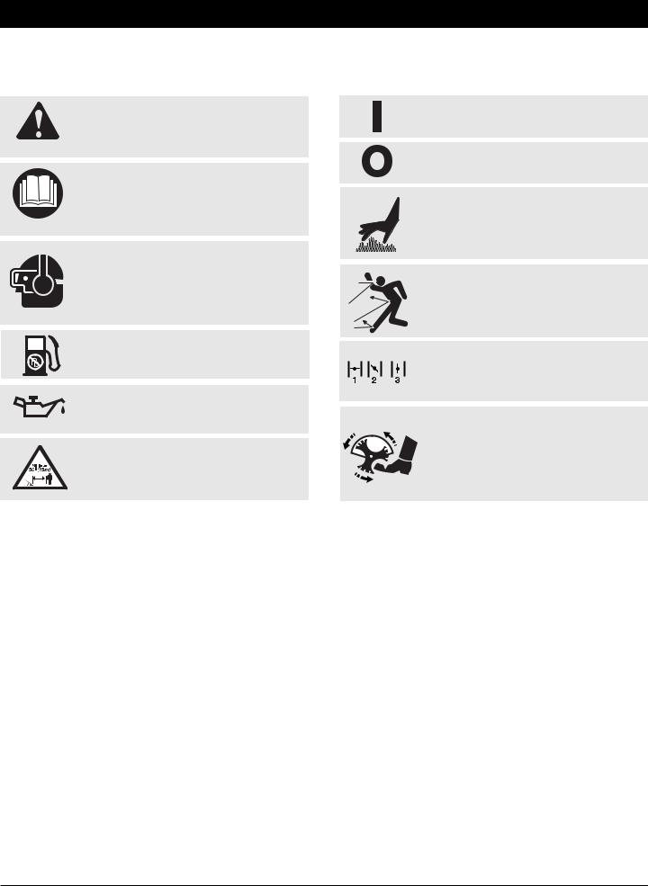
SAFETY AND INTERNATIONAL SYMBOLS
This operator's manual describes safety and international symbols and pictographs that may appear on this product. Read the operator's manual for complete safety, assembly, operating and maintenance and repair information.
SYMBOL |
MEANING |
SYMBOL |
MEANING |
|
• SAFETY ALERT SYMBOL |
|
• ON/OFF STOP CONTROL |
Indicates danger, warning or caution. May be used in conjunction with other symbols or pictographs.
•WARNING - READ OPERATOR'S MANUAL
Read the operator’s manual(s) and follow all warnings and safety instructions. Failure to do so can result in serious injury to the operator and/or bystanders.
•WEAR EYE AND HEARING PROTECTION
WARNING: Thrown objects and loud noise can cause severe eye injury and hearing loss. Wear eye protection meeting ANSI Z87.1 standards and ear protection when operating this unit. Use a full face shield when needed.
•UNLEADED FUEL
Always use clean, fresh unleaded fuel
•OIL
Refer to operator’s manual for the proper type of oil.
•KEEP BYSTANDERS AWAY
WARNING: Keep all bystanders, especially children and pets, at least 50 feet (15 m) from the operating area.
ON / START / RUN
•ON/OFF STOP CONTROL
OFF or STOP
•HOT SURFACE WARNING
Do not touch a hot muffler, gear housing or cylinder. You may get burned. These parts get extremely hot from operation. They remain hot for a short time after the unit is turned off.
•THROWN OBJECTS AND ROTATING CUTTER CAN CAUSE SEVERE INJURY
WARNING: Do not operate without the cutting attachment shield in place. Keep away from the rotating cutting attachment.
•CHOKE CONTROL
1.• FULL choke position
2.• PARTIAL choke position
3.• RUN choke position
•GARDEN EDGERS – ROTATING BLADE CAN CAUSE SEVERE INJURY
WARNING: Stop the engine and allow the blade to stop before removing the blade, or before cleaning or performing any maintenance. Keep hands and feet away from rotating blade.
3
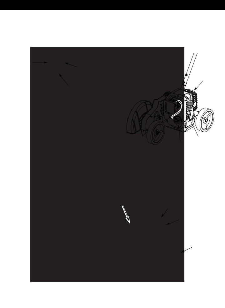
KNOW YOUR UNIT
APPLICATIONS
• Edging along paths, driveways, rockeries, etc.
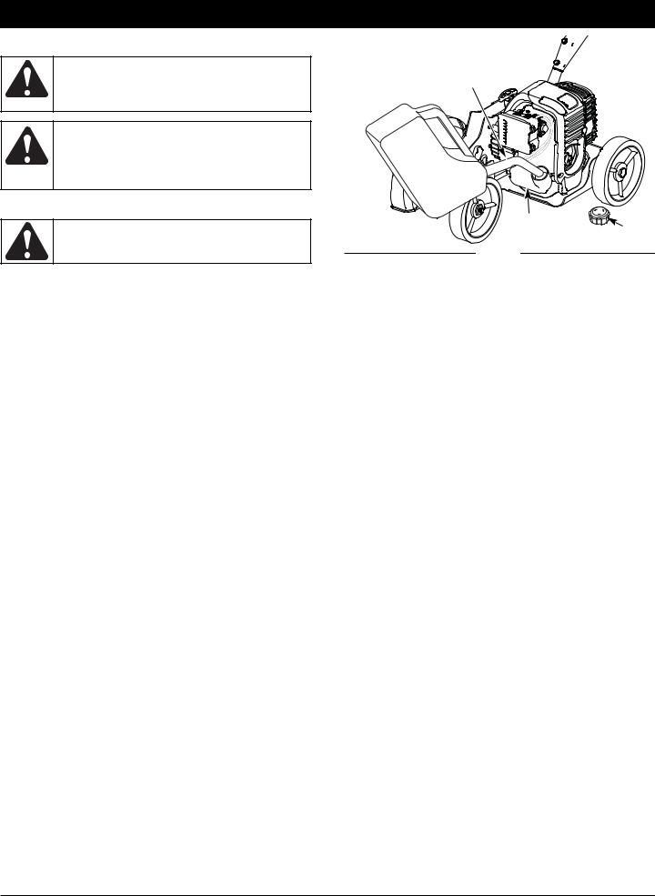
On/Off Switch 
Blade Clutch |
|
Lock-Out |
3-Position Throttle |
|
|
|
Control |
|
Blade Clutch Lever |
Starter Rope
Grip
Wheel 
Edger Blade 
Muffler
Oil Plug
Gas Tank
Spark Plug
 Choke Lever
Air Filter Cover
Depth Adjustment Lever
Wheel
Blade Shield
4
ASSEMBLY INSTRUCTIONS
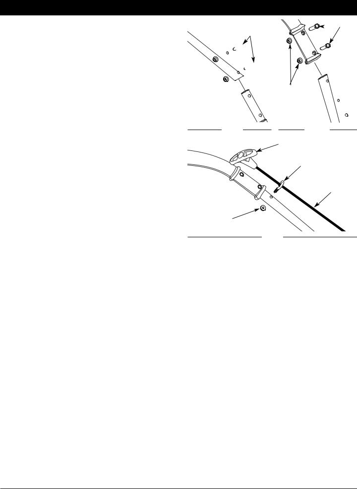
HANDLE ASSEMBLY
1.Remove the unit from the box.
2.Place the 2-holed end of the straight metal shaft over the shaft base on the unit and align the holes (Fig. 1).
3.Insert the two self-tapping screws (1/4” x 1-1/4”) into these holes (Fig. 1).
4.Using a 3/8” wrench, screw each self-tapping screw into the shaft until firm. DO NOT OVERTIGHTEN.
5.Insert the control handle onto the 3-holed end of the straight metal shaft and align the control handle’s holes with the two end holes of the straight metal shaft (Fig. 2).
NOTE: Because the control cables are pre-installed, care must be taken when installing the control handle to not pinch or bend the cables. This can damage them and cause them to function improperly.
6.Insert the two screws (1/4” x 1-1/2”) into the recessed hex holes on the handle (Fig. 2) and hold in place.
7.Hand-start the lock-nuts onto these bolts.
8.Using a 7/16” wrench, tighten each nut onto each bolt until firm.
9.Pull out the starter rope and run it into the eye hook (Fig. 3).
10.Insert the eye hook into the remaining hole on the straight metal shaft (Fig. 3).
11.Screw the nut onto the eye hook (Fig 3) and use a 7/16” wrench to tighten. DO NOT OVERTIGHTEN.
12.Using the zip tie in the hardware bag, secure the handle cables to the straight metal shaft mid-way between the eye hook and the motor housing.
Self-Tapping
 Bolts
Bolts
Screws
Lock-Nuts
Fig. 1 |
Fig. 2 |
Starter Rope Handle
Eye Hook
Starter Rope
Lock-Nut
Fig. 3
5
OIL AND FUEL INFORMATION
WARNING: OVERFILLING OIL CRANKCASE MAY CAUSE SERIOUS PERSONAL INJURY. Check and maintain the proper oil level in the crank case; it is important and cannot be overemphasized. Check the oil before each use and change it as needed.
See Changing the Oil.
RECOMMENDED OIL TYPE
Using the proper type and weight of oil in the crankcase is extremely important. Check the oil before each use and change the oil regularly. Failure to use the correct oil, or using dirty oil, can cause premature engine wear and failure. Use a high-quality SAE 30 weight oil of API (American Petroleum Institute) service class SF, SG, SH.
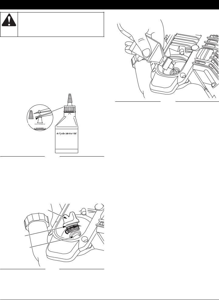
ADDING OIL TO CRANKCASE: INITIAL USE
NOTE: This unit is shipped without oil. In order to avoid damage to the unit, put oil in the crankcase before you attempt to start the unit.
Your unit is supplied with one 3.04 fluid oz. (90 ml.) bottle of SAE 30 SF, SG, SH oil (Fig. 4).
Funnel 


Spout
Fig. 4
NOTE: Save the empty oil bottle. It can be used to measure the correct amount during future oil changes. See Changing the Oil.
1.Unscrew the top of the bottle of oil and remove the paper seal covering the opening. Replace the top. Next, cut the tip off the funnel spout (Fig. 4).
2.Tip unit so that the back of the engine is facing up in a vertical position.
3.Remove the oil fill plug from the crankcase (Fig. 5).
Oil Fill Plug
O-Ring
4.Pour the entire bottle of oil into the oil fill hole (Fig. 6).
Fig. 6
NOTE: Never add oil to the gas or gas tank.
5.Wipe up any oil that may have spilled and reinstall the oil fill plug.
Check oil before each use and change as needed. Refer to Checking the Oil Level.
RECOMMENDED FUEL TYPE
Old gasoline is the primary reason for improper unit performance. Be sure to use fresh, clean, unleaded gasoline.
NOTE: This is a four cycle engine. In order to avoid damage to the unit, do not mix oil with the gasoline.
Definition of Blended Fuels
Today's fuels are often a blend of gasoline and oxygenates such as ethanol, methanol or MTBE (ether). Alcohol-blended fuel absorbs water. As little as 1% water in the fuel can form acids when stored. Use fresh fuel (less than 60 days old), when using alcohol-blended fuel.
Using Blended Fuels
If you choose to use a blended fuel, or its use is unavoidable, follow recommended precautions:
•Always use fresh unleaded gasoline
•Use a gas stabilizer fuel additive
•Drain tank and run the engine dry before storing unit
Using Fuel Additives
The use of a gas stabilizer will inhibit corrosion and minimize the formation of gum deposits. Using a fuel additive can keep fuel from forming harmful deposits in the carburetor for up to six (6) months. Add 0.8 oz. (23 ml.) of fuel additive per gallon of fuel according to the instructions on the container. NEVER add fuel additives directly to the unit's gas tank.
Oil Fill Hole
Fig. 5
6
OIL AND FUEL INFORMATION
FUELING THE UNIT
WARNING: Add fuel in a clean, well ventilated outdoor area. Wipe up any spilled fuel immediately. Avoid creating a source of ignition for spilt fuel. Do not start the engine until fuel vapors dissipate.
WARNING: Gasoline is extremely flammable. Ignited vapors may explode. Always stop the engine and allow it to cool before filling the fuel tank. Do not smoke while filling the tank. Keep sparks and open flames at a distance from the area.
1.Remove the gas cap.
WARNING: Remove fuel cap slowly to avoid injury from fuel spray. Never operate the unit without the fuel cap securely in place.
2.Place the gas container’s spout into the fill hole on the fuel tank (Fig. 7) and fill the tank.
NOTE: Fill or add gas to the tank only when the edger is in the horizontal position.
NOTE: Do not overfill the tank.
3.Wipe up any gasoline that may have spilled.
4.Reinstall the gas cap.
5.Move the unit at least 30 ft. (9.1 m) from the fueling source and site before starting the engine.
NOTE: Dispose of the old gasoline in accordance to Federal, State and Local regulations.
Gas Can Spout
Unleaded
Gas
Gas Tank
Gas Cap
Fig. 7
7
STARTING/STOPPING INSTRUCTIONS
WARNING: Operate this unit only in a wellventilated outdoor area. Carbon monoxide exhaust fumes can be lethal in a confined area.
WARNING: Avoid accidental starting. Make sure you are in the starting position when pulling the starter rope (Fig. 11). To avoid serious injury, the operator and unit must be in a stable position while starting.
STARTING INSTRUCTIONS
1.Check the oil level in the crankcase. Refer to
Checking the Oil Level.
2.Fill the fuel tank with fresh, clean unleaded gasoline. Refer to Fueling the Unit.
NOTE: There is no need to turn the unit on. The On/Off Stop Control is in the ON ( I ) position at all times (Fig. 8).

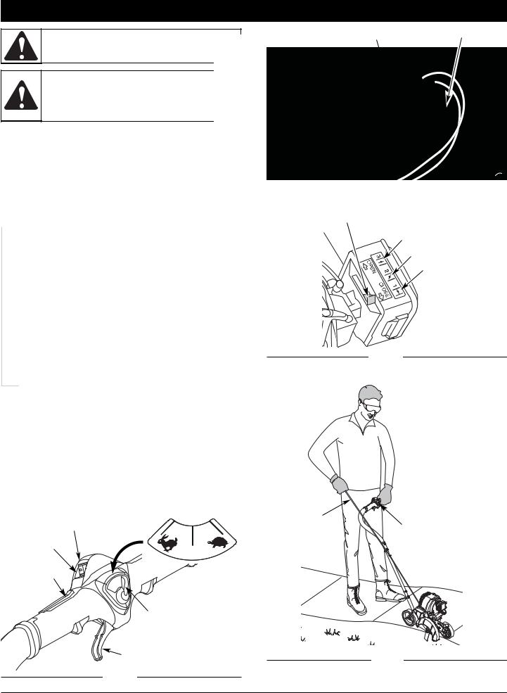
 3. Fully press and release the primer bulb 10 times, slowly. Some amount of fuel should be visible in the primer bulb and fuel lines (Fig. 9). If you can’t see fuel in the bulb, press and release the bulb as many times as it takes before you can see fuel in it.
4.Place the choke lever in Position 1 (Fig. 10).
5.Stand in the starting position (Fig. 11). Place the Throttle Control Lever in the Fast position (Fig. 8) and pull the starter rope briskly 5 times.
6.Place the choke lever in Position 2 (Fig. 10).
7.Pull the starter rope briskly 1 to 4 times to start the engine.
8.Allow the engine to warm up for 15 to 30 seconds.
9.Place the choke lever in Position 3 (Fig. 10). The unit is ready for use.
IF... the engine does not start, go back to step 3.
IF... the engine fails to start after a few attempts, place the choke lever in Position 3, move the throttle control lever to the fast position. Pull the starter rope briskly 3 to 8 times. The engine should start. If not, repeat.
STOPPING INSTRUCTIONS
1.Release your hand from the blade clutch lock-out and the blade clutch lever, and move throttle control lever to the slow position. Allow the engine to cool down by idling.
2.Press and hold On/Off Stop Control in the OFF (O) position until engine comes to a complete stop (Fig. 8).
Choke Lever |
Primer Bulb |
Fig. 9
Choke Lever
Position 3
Position 2
Position 1
Fig. 10
Stop/Off (O) |
Starter Rope |
Throttle Control |
Start/On ( I )
Fast Slow
Blade Clutch
Lock-Out
3-Position Throttle Control
Blade Clutch Lever |
Fig. 11 |
Fig. 8
8
OPERATING INSTRUCTIONS
HOLDING THE UNIT
WARNING: Always wear eye, hearing, foot and body protection to reduce the risk of injury when operating this unit.
Before operating the unit, stand in the operating position (Fig. 12). Check for the following:
•The operator is wearing eye protection and proper clothing.
•Both hands are holding the handle bar firmly.
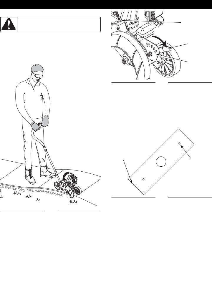
•The edger wheel adjusted for proper cut depth as shown in Figure 13 and edger positioned as shown in Figure 12.
Thumb
Wheel
Depth
Adjustment
Lever
Wheel
Bracket
Fig. 13
TIPS FOR BEST EDGING RESULTS
•Do not force the edger. Edge the first time at a lesser depth,(No more than 1/2” depth cut per pass), then do the area again with a deeper setting.
•Walk the edger at a slow, even pace
•Check the blade condition. As it wears it becomes smaller, thus reducing the cutting depth performance. Replace with a new blade when the blade has worn to the blade’s wear limit holes (Fig. 14).
Blade Edge
Wear Limit
Hole
Fig. 14
ADJUST BELT TENSION
Fig. 12
ADJUSTING EDGER CUTTING DEPTH
1.Grasp the depth adjustment lever located beside the front wheel (Fig 13).
2.To raise the cutting blade, move the lever toward the front of the wheel bracket (Fig. 13). Lowering the wheel decreases the cutting depth.
3.To lower the cutting blade, move the lever toward the rear of the wheel bracket. Raising the wheel increases the cutting depth.
If blade fails to turn when the blade clutch lock-out and the blade clutch lever are pressed, then:
1.Locate small thumb wheel on top of the belt housing (Fig. 13).
2.Turn the wheel clockwise 1 revolution to increase the tension on the belt.
3.Try depressing the blade clutch lock-out and the blade clutch lever and see if blade turns. If not, repeat step 2 until the blade turns.
9
MAINTENANCE AND REPAIR INSTRUCTIONS
WARNING: To prevent serious injury, never perform maintenance or repairs with unit running. Always service and repair a cool unit. Disconnect the spark plug wire to ensure that the unit cannot start.
MAINTENANCE SCHEDULE
Perform these required maintenance procedures at the frequency stated in the table. These procedures should also be a part of any seasonal tune-up.
NOTE: Some maintenance procedures may require special tools or skills. If you are unsure about these procedures take your unit to a Troy-Bilt or other qualified service dealer.
NOTE: Maintenance, replacement, or repair of the emission control devices and system may be performed by a Troy-Bilt or other qualified service dealer.
In order to assure peak performance of your engine, inspection of the engine exhaust port may be necessary after 50 hours of operation. If you notice lost RPM, poor performance or general lack of acceleration, this service may be required. If you feel your engine is in need of this inspection, refer service to a Troy-Bilt or other qualified service dealer for repair. DO NOT attempt to perform this process yourself as engine damage may result from contaminants involved in the cleaning process for the port.
FREQUENCY |
MAINTENANCE REQUIRED |
SEE |
|
|
|
|
|
Before starting engine |
Fill fuel tank with fresh fuel |
p. 6 |
|
Check oil |
p. 11 |
||
|
|||
|
|
|
|
Every 10 hours |
Clean and re-oil air filter |
p. 11 |
|
|
|
|
|
1st change at 10 hours |
Change oil |
p. 11 |
|
2nd change at 25 hours |
Change oil |
p. 11 |
|
Every 25 hours after |
Clean spark arrestor |
p. 13 |
|
|
|
|
|
10 hours on new engine |
Check rocker arm to valve clearance and adjust |
p. 12 |
|
Every 25 hours |
Check rocker arm to valve clearance and adjust |
p. 12 |
|
Every 25 hours |
Check spark plug condition and gap |
p. 13 |
|
|
|
|
BLADE REPLACEMENT
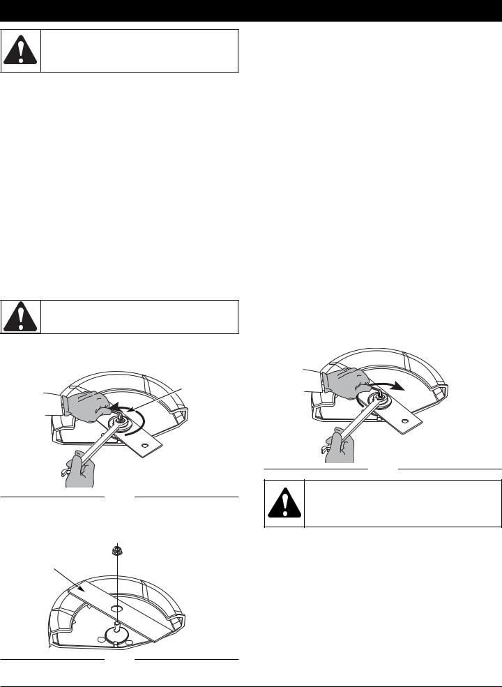
WARNING: To avoid serious personal injury, always wear gloves while handling, removing or installing the blade.
1.Place the 5/16” Allen wrench in the spindle hole (Fig. 15).
2.While holding the Allen wrench in place, loosen the nut with a 15/16” wrench by turning it counterclockwise (Fig. 15).
Spindle Hole
Loosen
Fig. 15
3.Remove the nut and blade. Keep the nut for new blade installation.
4.Install the new blade and nut (Fig. 16).
 Nut
Nut
Edger Blade
5.While holding the Allen wrench in the spindle hole, tighten the nut by turning the wrench clockwise until tight (Fig. 17).
NOTE: Make sure that the blade stays flat and centered against the output shaft throughout installation.
Tighten
Fig. 17
WARNING: Verify the blade is flat against the output shaft after the nut is tightened. If the blade is off-center, the unit will be damaged by vibration, and the blade may fly off, which can cause serious personal injury.
ACCESSORIES/REPLACEMENT PARTS
Blade . . . . . . . . . . . . . . . . . . . . . . . . . . . . . . . . . . . . . 753-05562
Nut . . . . . . . . . . . . . . . . . . . . . . . . . . . . . . . . . . . . . . 753-05549
Use only original Troy-Bilt replacement parts.
Fig. 16
10

MAINTENANCE AND REPAIR INSTRUCTIONS
CHECKING THE OIL LEVEL
The importance of checking and maintaining the proper oil level in the crankcase cannot be overemphasized. Check oil before each use:
1.Stop the engine and allow oil to drain into the crankcase.
2.Place the unit on a level surface to get a proper oil level reading.
3.Keep dirt, grass clippings and other debris out of the engine. Clean the area around the oil fill plug before removing it.
4.Remove the oil fill plug.
5.Look into the oil fill hole, use a flashlight if needed. The oil should be just touching the inner most thread (Fig. 18).
6.If the oil level is not touching the inner most thread on the oil fill hole, add a small amount of oil to the oil fill hole and recheck (Fig. 21). Repeat this procedure until the oil level reaches the inner most thread on the oil fill hole.
NOTE: Do not overfill the unit.
NOTE: Make sure the O-ring is in place on the oil fill plug when checking and changing the oil (Fig. 19).
Oil Fill Plug
O-Ring 

Oil Fill Hole 
Max Oil Fill Line
Fig. 18 |
|
|
|
Fig. 19 |
|
|
CHANGING THE OIL
For a new engine, change the oil after the first 10 hours of operation. Change the oil while the engine is still warm. The oil will flow freely and carry away more impurities.
WARNING: Wear gloves to prevent injury when handling unit.
1.Unplug spark plug boot to prevent accidental starting.
2.Remove the oil fill plug.
3.Pour the oil out of the oil fill hole and into a container by tipping the unit to a vertical position (Fig. 20). Allow ample time for complete drainage.
4.Wipe up any oil residue on the unit and clean up
any oil that may have spilled. Dispose of the
oil according to Federal,
State and local Fig. 20 regulations.
5.Refill the crankcase with 3.04 fluid ounce (90 ml) of SAE 30 SF, SG, SH oil.
NOTE: Use the bottle and spout saved from initial use to measure the correct amount of oil. The top of the label on the bottle measures approximately 3.04 ounces (90 ml) (Fig. 21). Check the level, See Checking the Oil Level. If the level is low, add a small amount of oil and recheck. Do not overfill (Fig. 21).
6.Replace the oil fill plug.
7.Reconnect the spark plug boot.
Fill Level
Fig. 21
AIR FILTER MAINTENANCE
WARNING: To avoid serious personal injury, always turn the unit off and allow it to cool before you clean or service it.
Cleaning the Air Filter
Clean and re-oil the air filter every 10 hours of operation. It is an important item to maintain. Failure to maintain your air filter properly can result in poor performance or can cause permanent damage to your engine.
1.Open the air filter cover. Push the tab on the left side of the cover in, swing the air filter cover out and off the air filter housing (Fig. 22).
Screen |
Air Filter |
Tab
Air Filter Cover
Choke Lever Air Filter Housing
Hooks
Slot |
Air Filter |
Tab |
|
Fig. 22 |
|||
|
|
2.Remove the air filter and the
screen that sits behind it (Fig. 22).
3. Wash the filter in detergent and water (Fig. 23). Rinse the filter thoroughly and allow it to dry.
4. Apply enough clean SAE 30 motor oil to lightly coat the filter (Fig. 24).
5.Squeeze the filter to spread and remove excess oil (Fig. 25).
6.Replace the filter (Fig. 22).
Fig. 23
11
MAINTENANCE AND REPAIR INSTRUCTIONS
ROCKER ARM CLEARANCE
This requires disassembly of the engine. If you feel unsure or unqualified to perform this, take the unit to an authorized service center.
NOTE: Inspect the valve to rocker arm clearance with a feeler gauge after the first 10 hours of operation and every 25 hours of operation.
• The engine must be cold when checking or adjusting the valve clearance.
• This task should be performed inside, in a clean, dust free area.
Fig. 24 |
|
|
|
Fig. 25 |
|
1. Remove the six (6) screws on the back of the engine cover |
|
|
|
|
|
|
with a Flat-head or T-25 Torx screwdriver (Fig. 27). |
|
|
|
|
|
|
NOTE: If the unit is operated without the air filter, you will VOID the warranty.
7.Reinstall the air filter cover. Position the tabs on the sides of the air filter cover onto the slots at the top of the back plate (Fig. 22).
8.Push the cover in until the tab on the air filter backplate snaps into place in the slot on the air filter cover (Fig. 22).
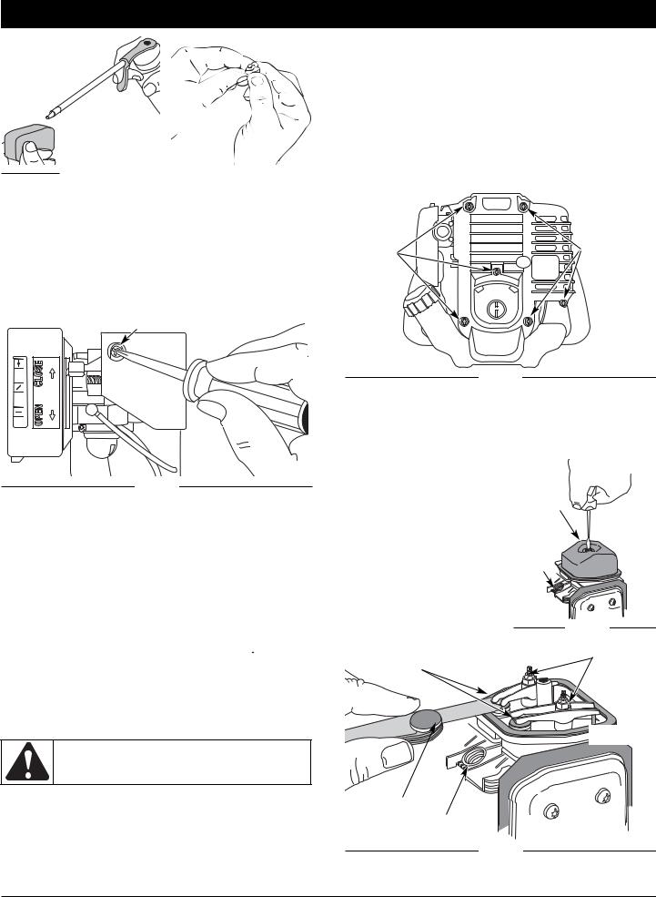
CARBURETOR ADJUSTMENT
The idle speed of the engine is adjustable. An idle adjustment screw is between the air filter cover and the engine starter housing (Fig. 26).
Idle Adjustment Screw
3 2 1
Fig. 26
NOTE: Careless adjustments can seriously damage your unit. An authorized service dealer should make carburetor adjustments.
Check Fuel
Old fuel is usually the reason for improper unit performance. Drain and refill the tank with fresh fuel prior to making any adjustments. Refer to Oil and Fuel Information.
Adjust Idle Speed Screw
If, after checking the fuel and cleaning the air filter, the engine still will not idle, adjust the idle speed screw as follows:
1.Start the engine and let it run at a high idle for a minute to warm up. Refer to Starting/Stopping Instructions.
2. Move the throttle control lever to the Slow position ( ) and let the engine idle. If the engine stops, insert a small phillips in between the Air Filter Cover and the Engine Cover (Fig. 26).
NOTE: Do not engage the Blade Clutch Lever while adjusting the idle speed screw to ensure that the blade will not rotate.
3.Turn the idle speed screw in, clockwise, 1/8 of a turn at a time (as needed) until the engine idles smoothly.
WARNING: To prevent serious personal injury, make sure the blade has stopped rotating before you turn it off.
Checking the fuel, cleaning the air filter, and adjusting the idle speed should solve most engine problems. If not and all of the following are true:
•the engine will not idle
•the engine hesitates or stalls on acceleration
•there is a loss of engine power
Have the carburetor adjusted by an authorized service dealer.
Remove |
Remove |
Screws |
Screws |
Fig. 27
2.Disconnect the spark plug wire.
3.Clean dirt from around the spark plug. Remove the spark plug from the cylinder head by turning a 5/8 in. socket counterclockwise.
4.Remove the engine cover (Fig. 27).
5.Clean dirt from around the rocker arm cover. Remove
the screw holding the rocker |
Rocker |
arm cover with a large flat |
Arm |
blade screwdriver or Torx T- |
Cover |
25 bit (Fig. 28). Remove the |
|
rocker arm cover and gasket. |
|
6.Pull the starter rope slowly to
bring the piston to the top of its |
Spark |
|
travel, (known as top dead |
Plug |
|
center). Check that: |
|
Hole |
• The piston is at the top of its |
|
|
travel while looking in the |
|
|
spark plug hole (Fig. 29) |
|
|
• Both rocker arms move |
|
|
freely, and both valves are |
Fig. 28 |
|
closed |
|
|
|
|
|
Rocker Arms |
INTAKE |
Adjusting Nuts |
|
||
|
|
|
EXHAUST
Feeler Gauge
Spark Plug
Hole
Fig. 29
If these statements are not true, repeat this step.
12
MAINTENANCE AND REPAIR INSTRUCTIONS
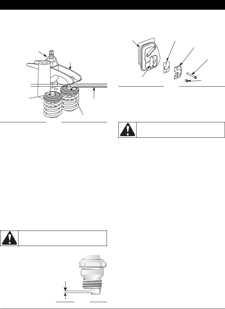
7.Slide the feeler gauge between the rocker arm and the valve return spring. Measure the clearance between the valve stem and rocker arm (Fig. 29). Measure both the intake and exhaust valves.
The recommended clearance for both intake and exhaust is
.003 – .006 in. (.076 – 0.152 mm). Use a standard automotive
.005 in. (0.127 mm) feeler gauge. The feeler gauge should slide between the rocker arm and valve stem with a slight amount of resistance, without binding. See Figures 29 and 30.
Adjusting Nut
Rocker Arm
.003–.006 in. (.076–.152 mm)
Intake Valve
Stem |
Feeler Gauge |
|
Exhaust Valve Stem
Fig. 30
8.If the clearance is not within specification:
a. Turn the adjusting nut using a 5/16 inch (8 mm) wrench or nut driver (Fig. 29).
SPARK ARRESTOR MAINTENANCE
1.Remove the rear engine cover. See Rocker Arm Clearance.
2.With a flat blade screwdriver or Torx T-20 bit and a T-25 bit, remove the screws attaching the spark arrestor cover to the muffler (Fig. 32).
Muffler |
Spark Arrestor Screen |
Diverter
 T-25 Screw
Slot
T-20 Screw
Fig. 32
3.Pull the tab on the spark arrestor cover out of the muffler. Remove the spark arrestor cover.
4.Remove the spark arrestor screen from the spark arrestor cover.
5.Clean the spark arrestor screen with a wire brush or replace it.
6.Reinstall the spark arrestor screen, spark arrestor cover and screws.
CLEANING
WARNING: To avoid serious personal injury, always turn your unit off and allow it to cool before you clean or service it.
•To increase clearance, turn the adjusting nut counterclockwise.
•To decrease clearance, turn the adjusting nut clockwise. b. Recheck both clearances, and adjust as necessary.
9.Reinstall the rocker arm cover using a new gasket. Torque the screw to 20–30 in•lb (2.2–3.4 N•m).
10.Check the spark plug and reinstall. See Replacing the Spark Plug.
11.Replace the spark plug wire.
12.Reinstall the engine cover. Check alignment of the cover before tightening the screws. Tighten screws.
REPLACING THE SPARK PLUG
Use a replacement part number 753-05255 spark plug. The correct air gap is 0.025 in. (0.635 mm). Remove the plug after every 25 hours of operation and check its condition.
1.Stop the engine and allow it to cool. Remove the six (6) screws on the back of the engine cover with a Flat-head or T-25 Torx screwdriver (Fig. 28).
2.Grasp the plug wire firmly and pull the cap from the spark plug.
3.Clean dirt from around the spark plug. Remove the spark plug from the cylinder head by turning a 5/8 in. socket counterclockwise.
WARNING: Do not sand blast, scrape or clean electrodes. Grit in the engine could damage the cylinder.
4.Replace cracked, fouled or dirty spark plug. Set the air gap at
0.025 in. (0.635 mm) using a
feeler gauge (Fig. 31).
5. Install a correctly-gapped spark plug in the cylinder head. Turn the 5/8 in. socket clockwise until snug.
If using a torque wrench torque to:
110-120 in.•lb. (12.3-13.5 N•m)
Do not over tighten.
Use a small brush to clean off the outside of the unit. Do not use strong detergents. Household cleaners that contain aromatic oils such as pine and lemon, and solvents such as kerosene, can damage plastic housing or handle. Wipe off any moisture with a soft cloth.
STORAGE
•Never store the unit with fuel in the tank where fumes may reach an open flame or spark.
•Allow the engine to cool before storing.
•Lock up the unit to prevent unauthorized use or damage.
•Store the unit in a dry, well-ventilated area.
•Store the unit out of the reach of children.
LONG TERM STORAGE
1.Drain all gasoline from the gas tank into a container. Do not use gas that has been stored for more than 60 days. Dispose of the old gasoline in accordance to Federal, State, and Local regulations.
2.Start the engine and allow it to run until it stalls. This ensures that all gasoline has been drained from the carburetor.
3.Allow the engine to cool. Remove the spark plug and put 5 drops of high quality motor oil into the cylinder. Pull the starter rope slowly to distribute the oil. Reinstall the spark plug.
NOTE: Remove the spark plug and drain all of the oil from the cylinder before attempting to start the edger after storage.
4.Change the oil, referring to Changing the Oil. Dispose of the old oil in accordance to Federal, State and Local regulations.
5.Thoroughly clean the unit and inspect for any loose or damaged parts. Repair or replace damaged parts and tighten loose screws, nuts or bolts. The unit is ready for storage.
TRANSPORTING
•Allow the engine to cool before transporting.
•Secure the unit while transporting.
•Drain the gas tank before transporting.
•Tighten gas cap before transporting.
Fig. 31
13

|
|
TROUBLESHOOTING |
||
|
|
|
|
|
|
|
|
|
|
|
LE MOTEUR REFUSE DE DÉMARRER |
|
|
|
|
|
|
|
|
|
C A U S E |
|
A C T I O N |
|
|
Empty fuel tank |
|
Fill fuel tank with new fuel |
|
|
|
|
|
|
|
Primer bulb wasn't pressed enough |
|
Press primer bulb fully and slowly 10 times |
|
|
Old fuel |
|
Drain gas tank and add fresh fuel |
|
|
|
|
|
|
|
Fouled spark plug |
|
Replace or clean the spark plug |
|
|
Plugged spark arrestor |
|
Clean or replace spark arrestor |
|
|
|
|
||
|
LE MOTEUR REFUSE DE SE METTRE AU RALENTI |
|
||
|
|
|
|
|
|
C A U S E |
|
A C T I O N |
|
|
Air filter is plugged |
|
Replace or clean the air filter |
|
|
|
|
|
|
|
Old fuel |
|
Drain gas tank and add fresh fuel |
|
|
Improper carburetor adjustment |
|
Adjust carburetor |
|
|
|
|
|
|
|
LE MOTEUR REFUSE D’ACCÉLÉRER |
|
|
|
|
|
|
|
|
|
C A U S E |
|
A C T I O N |
|
|
Old fuel |
|
Drain gas tank and add fresh fuel |
|
|
|
|
|
|
|
Blade bound with grass |
|
Stop the engine and clean the blade |
|
|
Dirty air filter |
|
Clean or replace the air filter |
|
|
|
|
|
|
|
Plugged spark arrestor |
|
Clean or replace spark arrestor |
|
|
LE MOTEUR MANQUE DE PUISSANCE OU SE CALE DURANT LA COUPE |
|||
|
|
|
|
|
|
C A U S E |
|
A C T I O N |
|
|
Old fuel |
|
Drain gas tank and add fresh fuel |
|
|
|
|
|
|
|
Fouled spark plug |
|
Replace or clean the spark plug |
|
|
Plugged spark arrestor |
|
Clean or replace spark arrestor |
|
|
|
|
|
|
|
Blade cutting depth too deep |
|
Adjust blade cutting depth |
|
|
LAME BLOQUÉE |
|
|
|
|
|
|
|
|
|
C A U S E |
|
A C T I O N |
|
|
Blade bound with grass |
|
Stop the engine and clean the blade |
|
|
|
|
|
|
|
Drive belt loose |
|
Adjust belt tension using tension wheel |
|
|
Drive belt broken |
|
Replace belt |
|
|
|
|
|
|
If further assistance is required, contact your authorized service dealer.
14

|
SPECIFICATIONS |
|
|
|
|
ENGINE* |
|
|
|
Engine Type.................................................................................................................................................................. |
Air-Cooled, 4-Cycle |
Displacement .................................................................................................................................................................... |
1.8 cu. in. (29 cc) |
Operating RPM ........................................................................................................................................................................... |
6,800+ rpm |
Idle Speed RPM .............................................................................................................................................................. |
2,800 - 3,600 rpm |
Ignition Type.................................................................................................................................................................................. |
Electronic |
On/Off Stop Control.................................................................................................................................................................... |
Momentary |
Valve clearance...................................................................................................................................... |
0.003–0.006 in. (0.076–0.152 mm) |
Spark Plug Gap ........................................................................................................................................................ |
0.025 inch (0.635 mm) |
Lubrication ................................................................................................................................................................................... |
SAE 30 Oil |
Crankcase Oil Capacity ........................................................................................................................................................ |
3.04 oz (90 ml) |
Fuel ............................................................................................................................................................................................... |
Unleaded |
Carburetor ............................................................................................................................................................... |
Diaphragm, All-Position |
Starter ....................................................................................................................................................................................... |
Auto Rewind |
Muffler ............................................................................................................................................................................. |
Baffled with Guard |
Throttle.................................................................................................................................................................................. |
Variable Speed |
Fuel Tank Capacity ................................................................................................................................................................. |
14 oz (414 ml) |
|
|
UNIT* |
|
|
|
Unit Weight . . . . . . . . . . . . . . . . . . . . . . . . . . . . . . . . . . . |
. . . . . . . . . . . . . . . . . . . . . . . . . . . . . . . . . . . . . . . . . . . . . . 22.1 lbs. (10.02 kg.) |
Cutting Depth (maximum) . . . . . . . . . . . . . . . . . . . . . . . . . |
. . . . . . . . . . . . . . . . . . . . . . . . . . . . . . . . . . . . . . . . . . . . . . . 1.75 in. (44.5 mm) |
*All specifications are based on the latest product information available at the time of printing. We reserve the right to make changes at any time without notice.
15

MANUFACTURER’S LIMITED WARRANTY FOR:
The limited warranty set forth below is given by Troy-Bilt LLC (“Troy-Bilt”) with respect with new merchandise purchased and used in the United States, its possessions and territories.
Troy-Bilt warrants this product against defects in material and workmanship for a period of two (2) years commencing on the date of original purchase and will, at its option, repair or replace, free of charge, any part found to be defective in material or workmanship. This limited warranty shall only apply if this product has been operated and maintained in accordance with the Operator’s Manual furnished with the product, and has not been subject to misuse, abuse, commercial use, neglect, accident, improper maintenance, alteration, vandalism, theft, fire, water or damage because of other peril or natural disaster. Damage resulting from the installation or use of any accessory or attachment not approved by Troy-Bilt for use with the product(s) covered by this manual will void your warranty as to any resulting damage.
This warranty is limited to ninety (90) days from the date of original retail purchase for any Troy-Bilt product that is used for rental or commercial purposes, or any other incomeproducing purpose.
HOW TO OBTAIN SERVICE: Warranty service is available, WITH PROOF OF PURCHASE THROUGH YOUR LOCAL AUTHORIZED SERVICE DEALER. To locate the dealer in your area, please check for a listing in the Yellow Pages or contact the Customer Service Department of Troy-Bilt by calling 1- 800-828-5500 or writing to P.O. Box 361131, Cleveland OH 44136-0019 or if in Canada call 1-800-668-1238. No product returned directly to the factory will be accepted unless prior written permission has been extended by the Customer Service Department of Troy-Bilt.
This limited warranty does not provide coverage in the following cases:
A.Tune-ups - Spark Plugs, Carburetor Adjustments, Filters
B.Wear items - Bump Knobs, Outer Spools,Cutting Line, Inner Reels, Starter Pulley,Starter Ropes, Drive Belts
C.Troy-Bilt does not extend any warranty for products sold or exported outside of the United States of America, its possessions and territories, except those sold through Troy-Bilt’s authorized channels of export distribution.
Troy-Bilt reserves the right to change or improve the design of any Troy-Bilt product without assuming any obligation to modify any product previously manufactured.
No implied warranty, including any implied warranty of merchantability or fitness for a particular purpose, applies after the applicable period of express written warranty above as to the parts as identified. No other express warranty or guaranty, whether written or oral, except as mentioned above, given by any person or entity, including a dealer or retailer, with respect to any product shall bind Troy-Bilt. During the period of the Warranty, the exclusive remedy is repair or replacement of the product as set forth above. (Some states do not allow limitations on how long an implied warranty lasts, so the above limitation may not apply to you.)
The provisions as set forth in this Warranty provide the sole and exclusive remedy arising from the sales. Troy-Bilt shall not be liable for incidental or consequential loss or damages including, without limitation, expenses incurred for substitute or replacement lawn care services, for transportation or for related expenses, or for rental expenses to temporarily replace a warranted product.
(Some states do not allow limitations on how long an implied warranty lasts, so the above limitation may not apply to you.)
In no event shall recovery of any kind be greater than the amount of the purchase price of the product sold. Alteration of the safety features of the product shall void this Warranty. You assume the risk and liability for loss, damage, or injury to you and your property and/or to others and their property arising out of the use or misuse or inability to use the product.
This limited warranty shall not extend to anyone other than the original purchaser, original lessee or the person for whom it was purchased as a gift.
How State Law Relates to this Warranty: This warranty gives you specific legal rights, and you may also have other rights which vary from state to state.
To locate your nearest service dealer dial 1-800-828-5500 in the United States or 1-800-668-1238 in Canada.
Troy-Bilt LLC
P.O. Box 361131
Cleveland, OH 44136-0019
 Loading...