


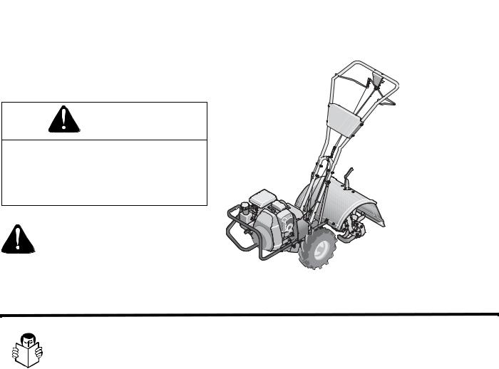
Operator’s Manual
Rear-tine Tiller Models
Bronco
Super Bronco
Pro-Line
IMPORTANT: Read safety rules and instructions carefully before operating equipment.
Warning: This unit is equipped with an internal combustion engine and should not be used on or near any unimproved forest-covered, brushcovered or grass-covered land unless the engine’s exhaust system is equipped with a spark arrester meeting applicable local or state laws (if any). If a spark arrester is used, it should be maintained in effective working order by the operator. In the State of California the above is required by law (Section 4442 of the California Public Resources Code). Other states may have similar laws. Federal laws apply on federal lands. A spark arrester for the muffler is available through your nearest engine authorized service dealer or contact the service department, P.O. Box 361131 Cleveland, Ohio 44136-0019.
|
Troy-Bilt LLC, P.O. BOX 361131 CLEVELAND, OHIO 44136-0019 |
PRINTED IN U.S.A. |
FORM NO. 769-02357B.fm |
|
12/19/06 |
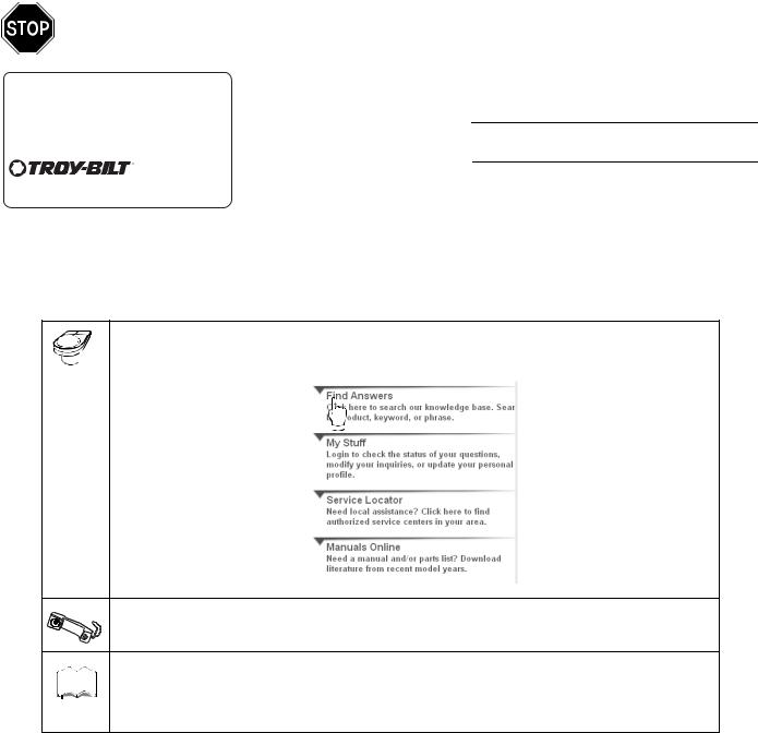
TABLE OF CONTENTS
Content |
Page |
Content |
Page |
Customer Support |
2 |
Maintenance |
17 |
Safety |
3 |
Off-season Storage |
21 |
Assembly |
6 |
Troubleshooting |
22 |
Features and Controls |
10 |
Parts List |
24 |
Operation |
12 |
Warranty |
Back Cover |
FINDING MODEL NUMBER
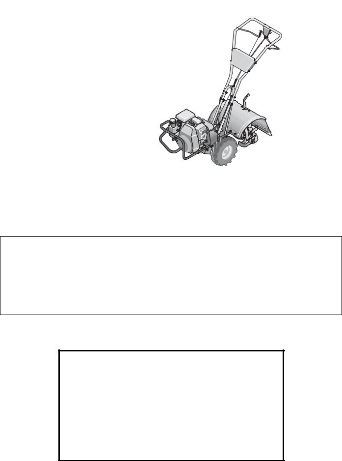
This Operator’s Manual is an important part of your new tiller. It will help you assemble, prepare and maintain the unit for best performance. Please read and understand what it says.
Before you start assembling your new equipment, please locate the model plate on the equipment and copy the information from it in the space provided below. A sample model plate is also given below. You can locate the model plate by looking at the rear of the tine shield. This information will be necessary to use the manufacturer’s web site and/or help from the Customer Support Department or an authorized service dealer.
TROY-BILT LLC
P. O. BOX 361131
www.troybilt.com CLEVELAND, OH 44136
330-558-7220
866-840-6483
Copy the model number here:
Copy the serial number here:
CUSTOMER SUPPORT
Please do NOT return the unit to the retailer without first contacting Customer Support.
If you have difficulty assembling this product or have any questions regarding the controls, operation or maintenance of this unit, you can seek help from the experts. Choose from the options below:
Visit troy-bilt.com for many useful suggestions. Click on Customer Support button and you will get the four options reproduced here. Click on the appropriate button and help is immediately available.
The answer you are |
|
The answer you are |
looking for could be just |
|
looking for could be just |
a mouse click away! |
|
a mouse click away! |
|
|
|
If you prefer to reach a Customer Support Representative, please call 1(866) 840-6483.
The engine manufacturer is responsible for all engine-related issues with regard to
Engine
Manual performance, power-rating, specifications, warranty and service. Please refer to the engine  manufacturer’s Owner’s/Operator’s Manual, packed separately with your unit, for more information.
2
SECTION 1: SAFETY
This machine meets voluntary safety standard B71.8 – 1996, which is sponsored by the Outdoor Power Equipment Institute, Inc., and is published by the American National Standards Institute.
WARNING
The engine exhaust from this product contains chemicals known to the State of California to cause cancer, birth defects or other reproductive harm.
Safety Alert Symbol
This is a safety alert symbol. It is used in this manual and on the unit to alert you to potential hazards. When you see this symbol, read and obey the message that follows it. Failure to obey safety messages could result in personal injury or property damage.
Forward Clutch Bail |
Reverse Clutch Control |
|
|
|
(Super Bronco & Pro-Line) |
|
Depth Regulator |
|
Tine Hood Flap |
|
Counter-Rotating-Tines |
|
(CRT) |
|
Wheel Drive Pin |
Figure 1-1: Tiller features and controls. See separate Engine Owner’s Manual to identify engine controls.
Training
1. Carefully read this Owner’s Manual, the separate Engine Owner’s Manual,
and any other literature you may receive. Be thoroughly familiar with the controls and the proper use of the tiller and its engine. Know how to stop the unit and disengage the controls quickly.
2. Never allow children to operate the tiller. Never allow adults to operate the tiller without proper instruction.
3. Keep the area of operation clear of all persons, particularly children and pets.
4. Keep in mind that the operator or user is responsible for accidents or hazards occurring to other people, their property, and themselves.
Preparation
1.Thoroughly inspect the area where the tiller is to be used and remove all foreign objects.
2.Be sure all tiller controls are released and both wheels are in the Wheel Drive position before starting the engine.
3.Do not operate the tiller without wearing adequate outer garments. Avoid loose garments or jewelry that could get caught in moving parts.
4.Do not operate the tiller when barefoot or wearing sandals, sneakers, or light footwear. Wear protective footwear that will improve footing on slippery surfaces.
5.Do not till near underground electric cables, telephone lines, pipes or hoses. If in doubt, contact your telephone or utility company.
6.Warning: Handle fuel with care; it is highly flammable and its vapors are explosive. Take the following precautions:
a. Store fuel in containers specifically designed for this purpose.
b. The gas cap shall never be removed or fuel added while the engine is running. Allow the engine to cool for several minutes before adding fuel.
c. Keep matches, cigarettes, cigars, pipes, open flames and sparks away from the fuel tank and fuel container.
d. Fill fuel tank outdoors with extreme care. Never fill fuel tank indoors. Use a funnel or spout to prevent spillage.
e. Replace all fuel tank and container caps securely.
f.If fuel is spilled, do not attempt to start the engine, but move the machine away from the area of spillage and avoid creating any source of ignition until fuel vapors have dissipated.
7.Never make adjustments when engine is running (unless recommended by manufacturer).
Operation
1. Do not put hands or feet near or under rotating parts.
2. Exercise extreme caution when on or crossing gravel drives, walks, or roads. Stay alert for hidden hazards or traffic.
3. After striking a foreign object, stop the engine, remove the wire from the spark plug wire and prevent it from touching the spark plug. Thoroughly inspect the machine for any damage and repair the damage before restarting and operating the machine.
4. Exercise caution to avoid slipping or falling.
3
5. If the unit should start to vibrate abnormally, stop the engine, disconnect the spark plug wire and prevent it from touching the spark plug, and check immediately for the cause. Vibration is generally a warning of trouble.
6. Stop the engine, disconnect the spark plug wire and prevent it from touching the spark plug, whenever you leave the operating position, before unclogging the tines, or when making any repairs, adjustments or inspections.
7.Take all possible precautions when leaving the machine unattended. Stop the engine. Disconnect the spark plug wire and move it away from the spark plug. Be sure that both wheels are in the Wheel Drive position.
8.Before cleaning, repairing, or inspecting, stop the engine and make certain all moving parts have stopped. Disconnect the spark plug wire and prevent it from touching the spark plug to prevent accidental starting.
9.The flap on the tine hood must be down when operating the tiller.
10.Never use the tiller unless proper guards, plates, or other safety protective devices are in place.
11.Do not run the engine in an enclosed area. Engine exhaust contains carbon monoxide gas, a deadly poison that is odorless, colorless, and tasteless.
12.Keep children and pets away.
13.Never operate the tiller under engine power if the wheels are in the Freewheel position. In the Freewheel position, the wheels will not hold the tiller back and the revolving tines could propel the tiller rapidly, possibly causing loss of control. Always engage the wheels with the wheel drive pins in the Wheel Drive position before
starting the engine or engaging the tines⁄wheels with the Forward Clutch Bail (all models) or the Reverse Clutch control (Super Bronco & Pro-Line).
14.Be aware that the tiller may unexpectedly bounce upward or jump forward if the tines should strike extremely hard packed soil, frozen ground, or buried obstacles like large stones, roots, or stumps.
If in doubt about the tilling conditions, always use the following operating precautions to assist you in maintaining control of the tiller:
a.Walk behind and to one side of the tiller, using one hand on the handle bars Relax your arm, but use a secure hand grip.
b.Use shallower depth regulator settings, working gradually deeper with each pass.
c.Use slower engine speeds.
d.Clear the tilling area of all large stones, roots or other debris.
e.Avoid using downward pressure on the handlebars. If need be, use slight upward pressure to keep the tines from digging too deeply.
f.Before contacting hard packed soil at the end of a row, reduce engine speed and lift the handlebars to raise the tines out of the soil.
g.In an emergency, stop the tines and wheels by releasing whichever clutch control is engaged. Do not attempt to restrain the tiller.
15.Do not overload the tiller’s capacity by attempting to till too deeply at too fast a rate.
16.Never operate the tiller at high transport speeds on hard or slippery surfaces. Look behind and use care when backing up.
17.Do not operate the tiller on a slope that is too steep for safety. When on slopes, slow down and make sure you have good footing. Never permit the tiller to freewheel down slopes.
18.Never allow bystanders near the unit.
19.Only use attachments and accessories that are approved by the manufacturer of the tiller.
20.Use tiller attachments and accessories when recommended.
21.Never operate the tiller without good visibility or light.
22.Never operate the tiller if you are tired; or under the influence of alcohol, drugs or medication.
23.Operators shall not tamper with the en- gine-governor settings on the machine; the governor controls the maximum safe operating speed to protect the engine and all moving parts from damage caused by overspeed. Authorized service shall be sought if a problem exists.
24.Do not touch engine parts which may be hot from operation. Let parts cool down sufficiently.
25.Please remember: You can always stop the tines and wheels by releasing the Forward Clutch Bail or on Super Bronco & Pro-Line the Reverse Clutch control,
(whichever control is engaged), or by moving the ignition switch and⁄or throttle control lever on the engine to “OFF” or “STOP”.
26.To load or unload the tiller, see the instructions in Section 4 of this Manual.
27.Use extreme caution when reversing or pulling the machine towards you.
28.Start the engine carefully according to instructions and with feet well away from the tines.
29.Never pick up or carry a machine while the engine is running.
Maintenance and Storage
1.Keep the tiller, attachments and accessories in safe working condition.
2.Check all nuts, bolts, and screws for proper tightness to be sure the equipment is in safe working condition.
3.Never store the tiller with fuel in the fuel tank inside a building where ignition sources are present such as hot water and space heaters, furnaces, clothes dryers, stoves, electric motors, etc.). Allow the engine to cool before storing the unit in any enclosure.
4.To reduce the chances of a fire hazard, keep the engine free of grass, leaves, or excessive grease.
5.Store gasoline in a cool, well-ventilated area, safely away from any sparkor flame-producing equipment. Store gasoline in an approved container, safely away from the reach of children.
6.Refer to the Maintenance sections of this Manual and the separate Engine Owner’s Manual for instructions if the unit is to be stored for an extended period.
7.Never perform maintenance while the engine is running or the spark plug wire is connected, except when specifically instructed to do so.
8.If the fuel tank has to be drained, do this outdoors.
4
Decals
For your safety and the safety of others, various safety and operational decals are located on your unit (see Figure 1-2).
Keep the decals clean and legible at all times. Contact your local service dealer or the factory for replacements if any decals are damaged or missing.
Refer to the Parts List pages in this Manual for decal locations, descriptions and part numbers.
Forward Clutch Bail
Starting Stabilization
Message (on engine)
Reverse Clutch Control
Operating Instruction
(Super Bronco & Pro-Line)
Warning Messages
 Hot Surfaces Warning
Figure 1-2: Location of safety and operating decals.
Operating Symbols |
|
|
|
|
|
|
|
|
|
|
|
R |
|
|
|
|
|
|
|
|
|
|
|
||
Varioussymbols(shownhere,withworddescriptions) |
|
|
|
|
|
|
|
|
|
|
|
|
maybeusedonthetillerandengine. |
CHOKE |
CHOKE |
REVERSE |
|||||||||
NOTE:Yourunitmaynothaveallofthesymbols. |
|
|
ON |
|
OFF |
ROTATING TINES |
||||||
|
|
|
|
|
|
|
|
|
|
|
|
|
|
|
|
|
|
|
|
|
|
|
BAIL |
BAIL |
|
|
|
|
|
|
|
|
|
|
|
|
|
|
|
|
|
|
|
|
|
|
|
ENGAGED |
DISENGAGED |
|
|
|
|
|
|
|
|
|
|
|
|
|
|
|
|
|
|
|
|
|
|
|
FAST |
SLOW |
STOP |
TILLER DIRECTION |
LEVER DIRECTION |
 WARNING
TO AVOID SERIOUS INJURY:
•READ THE OWNER’S MANUAL.
•KNOW LOCATIONS AND FUNCTIONS OF ALL CONTROLS.
•KEEP ALL SAFETY DEVICES AND SHIELDS IN PLACE AND WORKING.
•NEVER ALLOW CHILDREN OR UNINSTRUCTED ADULTS TO OPERATE TILLER.
•SHUT OFF ENGINE AND DISCONNECT SPARK PLUG WIRE BEFORE MANUALLY UNCLOGGING TINES OR MAKING REPAIRS.
•KEEP BYSTANDERS AWAY FROM MACHINE.
•KEEP AWAY FROM ROTATING PARTS.
•USE EXTREME CAUTION WHEN REVERSING OR PULLING THE MACHINE TOWARDS YOU.
5
SECTION 2: ASSEMBLY
WARNING: To prevent personal injury or property damage, do not start the engine until all assembly steps are complete and you have read and understand the safety and operating instructions in this manual.
INTRODUCTION
Carefully follow these assembly steps to correctly prepare your tiller for use. It is recommended that you read this Section in its entirety before beginning assembly.
NOTE: Various tiller models are presented in this Manual. Use only the information appropriate for your tiller model. Engine styles vary by model. Your engine may appear differently than those illustrated in this manual.
INSPECT UNIT
Inspect the unit and carton for damage immediately after delivery. Contact the carrier (trucking company) if you find or suspect damage. Inform them of the damage and request instructions for filing a claim. To protect your rights, put your claim in writing and mail a copy to the carrier within 15 days after the unit has been delivered. Contact Troy-Bilt LLC if you need assistance in this matter.
TOOLS / MATERIALS NEEDED
(2) 1/2” open-end wrench*
(2) 9/16" open-end wrench*
(1) 3/8" open-end wrench*
(1)Large adjustable wrench (Super Bronco & Pro-Line)
(1) Scissors (to trim plastic ties)
(1) Ruler (for belt tension check)
(1)Block of wood (to support tiller when removing wheels)
(1)Tire pressure gauge (for models with pneumatic tires)
(1) Clean oil funnel
(1)Motor oil. Refer to the Engine Owner’s Manual for oil specifications and quantity required.
* Adjustable wrenches may be used.
ASSEMBLY STEPS
STEP 1: UNPACKING INSTRUCTIONS
NOTE: While unpacking, do not severely bend any control cables.
1. The tiller weighs approximately 133 lbs. Do not attempt to remove it from the shipping platform until instructed to do so in these Assembly steps.
2.Remove any packaging material from the carton. Remove any staples from the bottom of the carton and remove the carton from the shipping platform.
3.Remove all unassembled parts and the separate hardware bag from the carton. Check that you have the items listed in the Loose Parts List (contact your local dealer or the factory items are missing or damaged).
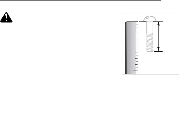
NOTE: Use the screw length template (Fig. 2-1) to identify screws.
Loose Parts List
Qty. |
Description |
1 |
Handlebar Support (see A, Fig. 2-2) |
1 |
Handlebar Assembly (see K, Fig. 2-2) |
4 |
Hardware bag contents: |
Hex hd. screw, 5/16-18 x 1-1/2" |
|
2 |
Hex hd. screw, 3/8-16 x 3/4" |
2 |
Flat Washer, 3/8" |
4 |
Split lock washer, 5/16" |
4 |
Hex nut, 5/16"-18 |
2 |
Hex locknut, 3⁄8"-16 |
*Super Bronco & Pro-Line IMPORTANT: Motor oil must be added to the engine crankcase before the engine is started. Follow the instructions in this Section and in the separate Engine Owner’s Manual.
NOTE: LEFT and RIGHT sides of the tiller are as viewed from the operator’s position behind the handlebars.
STEP 2: ATTACH HANDLEBAR
1. Loosely attach the legs of the handlebar support (A, Fig. 2-2) to the inner sides of the tiller frame using two 3/8"-16 x 3/4" hex hd. screws (B), 3/8" flat washers, and 3/8"- 16 hex locknuts.
1 |
2 |
Figure 2-1: To identify length of screws, place screw on template as shown and measure distance between bottom of screw head and tip of screw.
2.Using two 5/16"-18 x 1-1/2" screws (C), 5/16" split lock washers (D) and 5/16"-18 hex nuts (G), loosely attach the handlebar support (A) using the upper holes. Tighten the two screws securely.
3.There are three height adjustment holes in the two handlebar support brackets (E and F, Fig. 2-2). Use a setting that will position the handlebars at approximately waist level when the tines are 3"-4" into the soil. Loosely attach the support brackets to the outside of the handlebar assembly (I) using two 5/16"-18 x 1-1/2” screws (G), 5/ 16" split lock washers (D) and 5/16"-18 hex nuts (G). NOTE: If a support bracket will not move, loosen attaching screw (H) and nut.
IMPORTANT: The support brackets must be assembled to the outside of the handlebar assembly.
4. Tighten all handlebar mounting hardware securely.
STEP 3: MOVE TILLER OFF CRATE
To roll the tiller off the shipping platform, put the wheels in freewheel, as follows:
1. Place a sturdy block under the transmission to raise one wheel about 1" off the ground.
Remove the hairpin cotter (L, Fig. 2-3) and wheel drive pin (M) from the wheel hub (O) and wheel shaft (N).
6

I |
M |
O
N
The support brackets must
be assembled to the outside  L of the handlebar assembly.
|
|
Fig. 2-3: Wheel in FREEWHEEL position |
D |
|
(wheel drive pin through wheel shaft only). |
|
|
|
G |
A |
STEP 4: INSTALL FORWARD |
|
|
CLUTCH CABLE |
|
|
1. Carefully unwrap the forward clutch ca- |
|
|
ble (cable without an attached knob) from |
|
|
its shipping position and slide the thin ca- |
F |
C |
ble wire (M, Fig. 2-4) into the slot in the ca- |
|
ble bracket. Push the cable connector (N, |
|
E |
|
Fig. 2-4) up through the hole in the bracket |
|
until the groove in the connector snaps |
|
F |
|
into place. |
|
|
|
|
|
2. Thread the #10-24 hex nut (Z, Fig. 2-5) |
|
|
halfway onto the screw (V) which runs |
|
|
through the spring (W, Fig. 2-5). |
H |
|
3. Thread the screw (V) into the cable ad- |
|
juster (X). |
|
B |
|
|
|
|
|
Fig. 2.2: Attach handlebar. |
|
|
3.Slide the wheel fully inward on the wheel shaft (N, Fig. 2-3). Reinstall the wheel drive pin (M) through the wheel shaft only (not through the wheel hub). Secure the wheel drive pin with the hairpin cotter (L), pushing the hairpin cotter in as far as it will go. The wheel should now spin freely (freewheel) on the wheel shaft. Repeat with the other wheel.
4.Use the handlebar to roll the tiller to a flat area.
IMPORTANT: Before starting the engine, the wheels must be placed in the WHEEL DRIVE position (pins through wheel hubs and wheel shaft). This procedure is described in Wheel Drive Pins on page 10.
M
M
N
Fig. 2-4: Installing forward clutch cable bracket and cable.
7
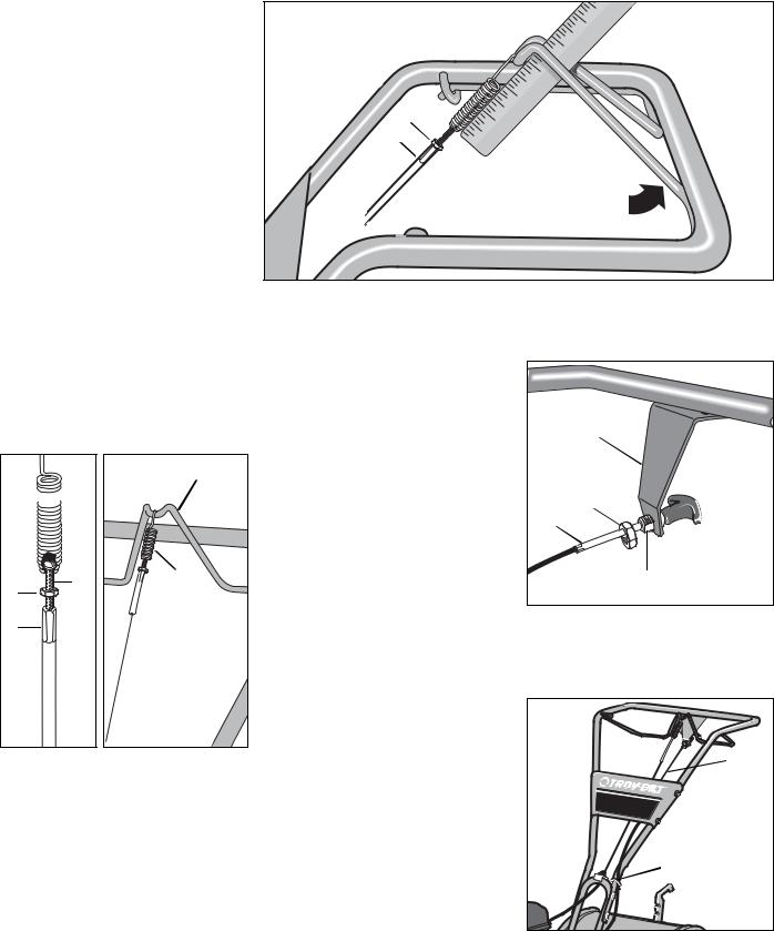
4. Check for correct tension on the forward drive belt by taking two measurements of the cable spring, as follows:
a.With the Forward Clutch Bail (Y, Fig. 2- 6) in an open (released) position, measure the length of the cable spring (W) from the outermost coil to the outermost coil.
b.Squeeze the Forward Clutch Bail against the handlebar (see Fig. 2-7) and re-mea- sure the spring length. The belt tension is correct if this second measurement is between 1/16" to 3/16" longer than the first measurement. If so, turn the hex nut (Z, Fig. 2-7) tightly against the cable adjuster
(X) while preventing the cable adjuster from turning.
c.If the spring length is incorrect, you must adjust the cable tension as described in Checking and Adjusting Forward Drive Belt Tension in Section 5. Incorrect cable tension can result in belt slippage (cable tension too loose), or unintentional tine movement when the clutch bail is in Neutral (cable tension too tight).
Y
W

V |
W |
Z |
|
X |
|
Fig. 2-5: Cable |
Fig. 2-6: Attach forward |
spring and |
clutch cable spring to |
adjuster. |
forward clutch bail. |
Z
X
Hold bail against handlebar while taking second measurement of spring
Fig. 2-7: To check forward belt tension, take two measurements of the length of the coils in the spring — first with the bail open, then with the bail held against the handlebar.
STEP 5: INSTALL REVERSE CLUTCH CABLE (SUPER BRONCO & PRO-LINE)
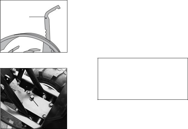
1.Unwrap the reverse clutch cable (CC, Fig. 2-8 and Fig. 2-9) from its shipping position and route it up to the handlebar. Be sure that the cable is routed beneath the Forward Clutch Bail.
2.Insert the cable (CC, Fig. 2-8) through the slot in the cable bracket and position the flat side of the threaded assembly next to the flat side of the hole. Slide the hex nut (DD) up the cable and tighten it securely.
3.Fasten the reverse clutch cable to the left side handlebar with a cable tie (EE, Fig. 2-9).
4.Test the function of the reverse clutch by pulling out and releasing the cable knob. The knob should return to its neutral position (resting against bracket). If it doesn’t, contact your local dealer or Troy-Bilt LLC for technical assistance.
BB |
DD |
CC |
Flat Side |
Fig. 2-8: Install reverse cable bracket and reverse clutch cable.
 CC
CC
BRONCO
 EE
EE
Fig. 2-9: Route reverse clutch cable (CC) as shown. Attach with cable tie (EE).
8
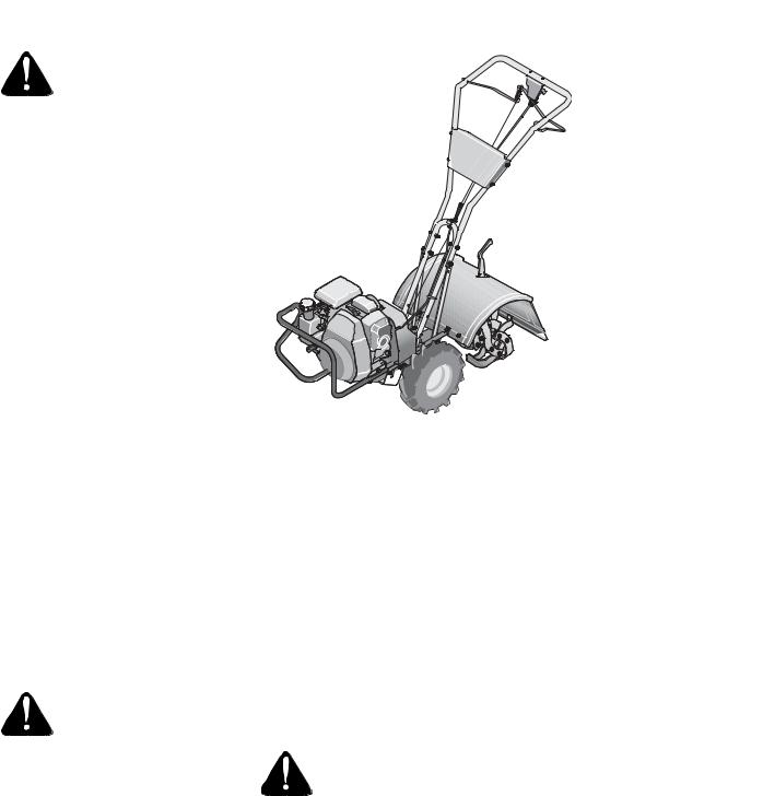
STEP 6: CHECK TRANSMISSION OIL LEVEL
The transmission was filled with gear oil at the factory. However, you should check the gear oil level at this time to make certain it is correct.
IMPORTANT: Do not operate the tiller if the gear oil level is low. Doing so will result in severe damage to the transmission components.
1.With the tiller on level ground, pull the Depth Regulator Lever (FF, Fig. 2-10) back and then all the way up until the lowest notch in the lever is engaged.
2.Remove the oil fill plug (GG, Fig. 2-11) from the transmission housing cover and locate the main drive shaft situated inside the housing.
3.The gear oil level is correct if the gear oil is approximately halfway up the side of the main drive shaft.
4.If the oil level is low, add gear oil by referring to A. To Check the Transmission Gear Oil Level in Section 5.
FF
STEP 7: ADD MOTOR OIL
The tiller is shipped without oil in the engine.
IMPORTANT: Do not start the engine without first adding motor oil. Severe engine damage will result if the engine is run without oil.
1.Refer to the separate Engine Owner’s Manual for engine oil specifications and capacities.
2.With the tiller on level ground, move the Depth Regulator Lever (FF, Fig. 2-10) up or down until the engine is level.
3.Add motor oil as described in the Engine Owner’s Manual.
4.Move the Depth Regulator Lever all the way down until the highest notch is engaged. This places the tines in the “travel” position, which allows the tiller to be moved without the tines touching the ground.
STEP 8: CHECK HARDWARE
Check all nuts and screws for tightness.
STEP 9: CHECK AIR PRESSURE IN TIRES (units with pneumatic tires)
Check the air pressure with a tire gauge. Deflate or inflate the tires equally to between 15 PSI and 20 PSI (pounds per square inch). Be sure that both tires are inflated equally or the unit will pull to one side.
Fig. 2-10: Adjust Depth Regulator Lever.
IMPORTANT: This completes the assembly steps. Before operating your tiller, make sure you read the following sections in this Manual, as well as the
separate Engine Owner’s Manual:
• Section 1: Safety
• Section 3: Features and Controls
• Section 4: Operation
GG
Fig. 2-11: Remove gear oil fill plug.
9
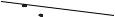
SECTION 3: FEATURES AND CONTROLS
WARNING: Before
operating your machine, carefully read and understand all safety, controls and operating instructions in this Manual, the separate Engine Owner’s Manual, and on the decals on the machine. Failure to follow these instructions can result in serious personal injury.
INTRODUCTION
This Section describes the location and function of the controls on your tiller. Refer to the following Section, Operation for detailed operating instructions.
Practice using these controls, with the engine shut off, until you understand the operation of the controls and feel confident with each of them.
ENGINE CONTROLS
Refer to the engine manufacturer’s Engine Owner’s Manual (included in the tiller literature package) to identify the controls on your engine.
IMPORTANT: The control for stopping the engine is located on the engine.
WHEEL DRIVE PINS
Each wheel is equipped with a wheel drive Klik pin (A, Figures 3-2 and 3-3) that secures the wheel to the wheel shaft (B). The wheels can be positioned in either a WHEEL DRIVE or a FREEWHEEL mode.
WARNING: Never allow either of the wheels to be in the FREEWHEEL position when the engine is running. Always put both wheels in the WHEEL DRIVE position before starting the engine.
Failure to comply could cause loss of tiller control, property damage, or personal injury.
Before starting the engine, put both wheels in the WHEEL DRIVE position by inserting the wheel drive pins through the wheel hubs and the wheel shaft, and secure with cotter pin. Doing so “locks” the wheels to the wheel shaft, causing the wheels to turn when either the
Forward Clutch Bail 
Reverse Clutch Control
Super Bronco & Pro-Line
 Depth Regulator
 Handlebar Height Adjustment


 Wheel Drive Pin
(on each wheel)
Figure 3-1: Tiller features and controls. See separate Engine Owner’s Manual to identify
engine controls.
Forward Clutch Bail (all models) or the Reverse Clutch Control (Super Bronco & ProLine) is engaged.
Use the FREEWHEEL mode only when the engine is not running. In FREEWHEEL, the wheel drive pins are placed only through the holes in the wheel shaft (not the wheel hubs), thus allowing the wheels to turn freely when you manually move the tiller.
To place the wheels in WHEEL DRIVE or FREEWHEEL:
1. Stop engine, disconnect spark plug wire from spark plug and allow engine to cool.
WARNING: Do not place tiller on its side when changing wheel drive positions. Doing so could result in gasoline leaking from the fuel tank.
Failure to follow this instruction could result in personal injury or property damage.
2.Raise one wheel about one inch off the ground and place a sturdy support under the transmission.
3.Remove Clevis Pin and cotter pin (A, Figures 3-2 and 3-3) from wheel drive shaft (B).
A
D
B
C
Figure 3-2: WHEEL DRIVE position.
4.FOR WHEEL DRIVE MODE (Figure 3-2): Slide wheel outward and align holes in wheel hub (D, Figure 3-2) and wheel shaft (B). Insert Clevis pin (A) through wheel hub (D) and wheel shaft (B) and secure with Cotter Pin (C). Repeat with the other wheel and then remove the support from beneath the transmission.
5.FOR FREEWHEEL MODE (Figure 3-3): Slide the wheel inward and insert the Clevis Pin (A, Figure 3-3) secured by the cotter pin (C) only through the hole in the wheel shaft (B). Repeat for the other wheel and then remove the support from beneath the transmission.
10
 Loading...