


®
Owner/Operator
Manual
Snowthrower
• Safety
• Assembly
• Controls
• Operation
• Maintenance
Models
42010 - 8 HP, 24" Auger
42030 - 8 HP, 24" Auger
42012 - 10 HP, 26" Auger
42031 - 10 HP, 26" Auger
GARDEN WAY INCORPORATED
Dear Owner:
Thank you for purchasing this product. The unit was carefully designed and manufactured to provide excellent performance if properly operated and maintained.
Read this manual. This is a safety, operation and general maintenance manual which does not attempt to cover major repairs. This manual is considered a permanent part of the unit and it must stay with the unit if it is resold. A replacement manual can be obtained from the factory. All information in this manual is based on the latest product information available at the time of printing. Review this manual frequently to familiarize yourself with the unit, its features and safe operation.
Our products have met the
safety standards of the |
|
|
|
IN |
|
|
|
|
|
|
|
NDE |
|
|
|
||
|
|
|
|
D |
|
|
|
|
|
|
|
BY |
E |
|
|
|
|
|
|
|
E |
|
|
|
|
|
|
|
CERTIFIEDGRA |
P |
|
|
|
|
|
|
|
|
SO |
A |
|
|||
Outdoor Power Equipment |
|
|
|
S |
N |
|
|
|
|
|
|
P |
|
T |
|
|
|
MODEL |
|
M |
ON |
L |
ATO |
|||
|
|
|
|
Y |
||||
|
|
O |
|
|
RE |
B |
|
|
|
|
PR |
|
|
|
D |
O |
|
|
|
|
|
|
|
B |
R |
|
Institute and an |
OUTDOOR |
POWER EQUIPMENT |
INSTITUTE |
R |
||||
ANS B71.1-1986 SAFETY STANDARD |
Y |
|||||||
|
||||||||
independent testing
The warranty statement is literature package. Read please complete and return registration card included purpose of the card is to owner at the factory to safety literature.
If you have any problems concerning the unit, contact authorized dealer or the numbers and mailing
page 3 and on the back of
We want to ensure your all times.
WARNING:
The engine exhaust from this product contains chemicals known to the State of California to cause cancer, birth defects or other reproductive harm.
Safety Alert Symbol
This is a safety alert symbol.
It is used in this manual and on the unit to alert you to
potential hazards. When you see this symbol, read and obey the message that follows it. Failure to obey safety messages could result in personal injury or property damage.
Owner
Registration
Card
Please fill out and
mail the enclosed Owner Registration
Card. The purpose of this card is to register each unit and owner at the factory to provide information and
your unit’s literature package.
Model/Serial Numbers
The model/serial numbers are located on the back of the unit. For quick reference, record these numbers in the spaces below.
Date of Purchase:
______________________________
Model/Serial Numbers:
______________________________
Left and Right Sides
Left and right sides of the unit are determined from the operator position, facing the direction of forward travel.
2
Customer Service
and Technical
Service
If you have questions or problems with the unit, contact your authorized dealer or
call or write the factory. (When calling or writing the factory, provide the model/serial numbers of the unit.)
Replacement Parts
Factory specified replacement parts are available from either your authorized dealer or directly from the
factory. For parts ordering information, refer to the parts catalog.
Engine Service and Repair
For engine service or repair, contact your nearest authorized engine dealer. To locate your nearest
engine dealer, look in the Yellow Pages under “Engines–Gasoline.” The engine on the unit is warranted by the engine manufacturer. Any unauthorized work performed on the engine during the warranty period may void the warranty. For complete details on the engine warranty, refer to the engine owner manual.
To Contact the Factory:
Garden Way Incorporated
1 Garden Way
Troy, New York 12180
Customer Service: 1-800-437-8686
Technical Service: 1-800-520-5520
Parts Service: 1-800-648-6776
FAX: (518) 391-7332
Outside the U.S.A. and Canada:
Customer Service: (518) 391-7007
Technical Service: (518) 391-7008
Parts Service: (518) 391-7006
FAX: (518) 391-7332
Table of Contents |
|
SECTION 1: SAFETY ..................................................................... |
4 |
Safety Decals ............................................................................................................ |
7 |
SECTION 2: ASSEMBLY ................................................................. |
8 |
Inspect Unit/Tools Required/Unpacking/Hardware Bag Contents .............................. |
8 |
Install Handlebars...................................................................................................... |
9 |
Install Discharge Chute/Attach Chute Control Rod .................................................... |
10 |
Attach Auger Drive Control Rod ................................................................................ |
11 |
Install Wheel/Gear Shift Control Rods ....................................................................... |
12 |
Install Wiring Harness/Adding Oil to the Engine/Check Gear Case Oil ....................... |
13 |
Check Tire Pressure/Install (optional) Drift Slicers .................................................... |
13 |
SECTION 3: CONTROLS .................................................................. |
14 |
Wheel/Auger/Gear Shift Control Levers .................................................................... |
14 |
Discharge Chute Controls/Ignition Keyswitch/Fuel Shut-Off Valve ........................... |
14 |
Engine Throttle/Primer ............................................................................................. |
15 |
Engine Starter/Choke................................................................................................ |
15 |
Skid Shoes/Scraper Blade/Handlebar Warmer.......................................................... |
15 |
SECTION 4: OPERATION ................................................................ |
16 |
Pre-Operation Checklist............................................................................................ |
16 |
Starting the Engine ................................................................................................... |
18 |
Stopping the Engine ................................................................................................. |
18 |
Auger Drive Engagement/Disengagement ................................................................ |
19 |
Wheel Drive Engagement/Disengagement ................................................................ |
19 |
Shifting Gears........................................................................................................... |
19 |
Transporting the Unit/Snowthrowing Patterns ......................................................... |
20 |
SECTION 5: MAINTENANCE ............................................................ |
21 |
Engine ...................................................................................................................... |
21 |
Lubrication ............................................................................................................... |
22 |
Wheel Drive .............................................................................................................. |
23 |
Shear Bolts ............................................................................................................... |
23 |
Auger Drive .............................................................................................................. |
24 |
Slip Differential ........................................................................................................ |
25 |
Gear Shift Rod .......................................................................................................... |
25 |
Drive Disk Clearance................................................................................................. |
25 |
Brake Arm Adjustment ............................................................................................. |
26 |
Skid Shoes/Scraper Blade ........................................................................................ |
26 |
Off-Season Storage .................................................................................................. |
26 |
Troubleshooting Chart.............................................................................................. |
27 |
Maintenance Schedule............................................................................................. |
29 |
Specifications ........................................................................................................... |
30 |
Wiring Diagram ........................................................................................................ |
31 |
3
Section
1 Safety
SPARK ARRESTER WARNING TO
RESIDENTS OF CALIFORNIA AND
SEVERAL OTHER STATES
Under California law, and under the laws of several other states, you are not permitted to operate an internal combustion engine using hydrocarbon fuels on any forest, brush, hay, grain, or grass covered
land; or land covered by any flammable agricultural crop without an engine spark arrester in continuous effective working order.
The engine on the unit is an internal combustion engine which burns gasoline, a hydrocarbon fuel, and must be equipped with a spark arrester muffler in continuous effective working order. The spark arrester must be attached to the engine exhaust system in such a manner that flames or heat from the system will not ignite flammable material. Failure of the owner/operator of the unit to comply with this regulation is a misdemeanor under California law (and other states) and may also be a violation of other state and/or federal regulations, laws, ordinances or codes. Contact your local fire marshal or forest service for specific information about which regulations apply in your area.
Training
1.Read this owner/operator manual and the separate engine owner manual carefully before operating the unit. Be completely familiar with the controls and the proper use of the unit. A replacement manual is available by contacting the factory.
2.Never allow children or untrained adults to use the unit.
3.Keep the area of operation clear of all people, particularly small children and pets. Keep bystanders at least 25 feet away from the area of operation.
4.Familiarize yourself with all of the safety and operating decals on the unit and on any attachments or accessories.
5.Do not run the engine in an enclosed area. Engine exhaust contains carbon monoxide gas, a deadly poison that is odorless, colorless, and tasteless. Do not operate the unit near buildings, windows, or air conditioners.
6.Keep hands or any other part of the body or clothing away from the inside of the auger housing, discharge opening, or moving parts.
7.Before inspecting, servicing or adjusting any part of the unit, shut the
engine off, wait for all moving parts to stop, and disconnect the spark plug wire from the spark plug. Secure the wire away from the spark plug.
8.Do not operate the unit if you are under the influence of alcohol, medication, or when tired or ill.
Preparation
1.Wear approved safety glasses or eye shields and hearing protection when operating the unit. The operation of any powered machine can result in foreign objects being thrown by highspeed rotating parts.
2.Do not wear loose-fitting clothing, such as scarves, which could be caught by moving parts. Tie up or restrain long hair.
4

Section 1: Safety
3.Before starting the engine, check the tightness of all screws, nuts, bolts, and other fasteners. Replace or clean any damaged or unreadable safety and operating labels.
4.Wear adequate winter outer garments when operating the unit. Wear footwear that will improve footing on slippery surfaces. Exercise caution to avoid slipping or falling, especially when operating in reverse.
5.Use extra care when handling gasoline and other fuels. Gasoline and its vapors are highly flammable and explosive. To help prevent a fire or explosion:
a.Store gasoline only in an approved gasoline storage container, safely out of the reach of children.
b.Never remove the fuel fill cap on the fuel tank, or add fuel while the engine is running or hot.
c.Keep matches, smoking materials, open flames, and sparks away from the fuel tank and gasoline storage container.
d.Fill the fuel tank outdoors and with extreme care. Never fill the fuel tank indoors.
e.Replace the fuel fill cap on the fuel tank, the cap on the gasoline storage container, and clean up fuel spills before starting the engine.
f.Leave 1/2-inch (2.5 cm) of air space at the top of the fuel tank to allow for fuel expansion.
g.Do not store the unit or the gasoline storage container where there is a danger of an open flame or spark, or where ignition sources are present such as hot water and space heaters, furnaces, clothes dryers, stoves, electric motors, etc.
6.For units equipped with the electricstart kit:
a.Only use a 3-pronged, UL rated and approved, outdoor use electrical cord.
b.Only plug into a properly grounded, 3-pronged outlet. Do not use any adapters on the cord.
c.Inspect the electrical cord for damage before use. If it is damaged, do not use it.
d.Stand on dry ground when handling the electrical cord. Do not handle the electrical cord with wet hands or wet gloves. Do not use the electric starter if it is raining.
e.Connect the cord to the electric starter first, and then plug the cord into a properly grounded outlet (this lessens the chances of sparks from occurring near the engine).
f.Do not abuse the electrical cord. Do not pull the unit by the cord. Do not pull the cord to disconnect it from the outlet. Keep the cord away from sharp edges, oil, and excessive heat.
7.Adjust the skid shoes and scraper blade so the auger housing clears gravel or crushed rock surfaces.
Operation
1.The operator of the unit is responsible for the safety of all persons in the operating zone of the unit.
2.Before starting the unit, disconnect the spark plug wire and check the auger and discharge chute to make sure they are free of ice. Check the engine oil level. Reconnect the spark plug wire before starting the engine.
3.Disengage all clutches and shift into neutral before starting the engine.
4.Let the unit adjust to outdoor temperature before use.
5.Check the operation of the controls before using the unit. Do not operate the unit unless all controls are operating properly.
6.Never carry passengers on the unit. They could fall off and be seriously injured, or they could interfere with safe operation.
7.Keep hands, other body parts, and clothing away from any moving or rotating parts. Keep clear of the intake and discharge openings at all times.
8.Before starting the engine, inspect the area where the unit is to be used and remove all sleds, boards, doormats, metal, bottles, cans, or other debris.
9.Keep children out of the area of operation and under the watchful eye of an adult not operating the unit. Never assume that children will remain where you last saw them.
10.If the unit makes an unusual noise or vibration, immediately shut the engine off, wait for all moving parts to stop, disconnect the spark plug wire from the spark plug and perform the following steps:
a.Inspect for damage.
b.Replace or repair any damaged parts.
c.Check for and tighten any loose parts.
5

Section 1: Safety
11.Before inspecting the unit or making any adjustments, or if the unit jams or becomes clogged, shut the engine off immediately and allow all moving parts to come to a stop. Disconnect the spark plug wire from the spark plug and secure the wire away from the spark plug. Use only a wooden stick (at least 3 feet long) to clear away any blockage.
12.Keep all guards, covers, shields and safety devices in place and in good working condition. Do not attempt to defeat the purpose of any safety device.
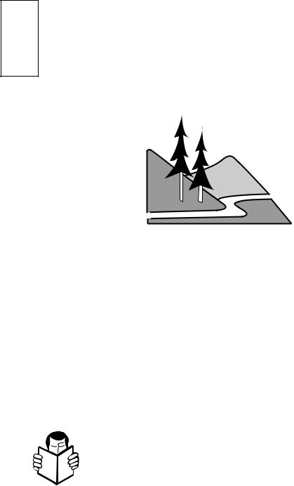
13.Exercise extreme caution on slopes.
14.Do not attempt to clear steep slopes.
15.Do not clear snow across the face of slopes. Exercise extreme caution when changing direction on slopes.
16.Always observe the terrain. Watch for and avoid obstacles. Stay away from holes, ditches, soft or steep embankments and other potentially dangerous terrain. Deep snow can hide obstacles and drop-offs.
17.Do not use the unit near drop-offs, ditches, or embankments. If a wheel goes over an edge, or if an edge caves in, the unit could overturn.
18.Do not operate the unit at high transport speeds on slippery surfaces. Wet surfaces reduce traction and stability.
19.Look behind and use care when operating the unit in reverse. If you have to pull the unit backward, disengage the auger and wheel drives. Always check behind you for hazards.
20.Be extremely careful when using the unit near blind corners, shrubs, trees, and other objects that may obscure vision.
21.Be extremely careful when operating near or crossing gravel drives, walks or roads. Stay alert for hidden hazards or traffic.
22.Remove any hearing protection and watch for traffic when operating near, or when crossing roadways.
23.Do not leave the unit unattended with the engine running. Stop the engine, let all moving parts come to a stop, and disconnect the spark plug wire from the spark plug before leaving the unit.
24.Use only attachments and accessories that are approved for use with the unit. Contact the factory customer service department, at the address and phone number on page 3, if you are not sure about the use of any attachment or accessory.
25.Operate the unit only in daylight or in good artificial light.
26.Do not tamper with the engine governor settings. The governor controls the maximum safe engine operating speed and protects the engine and moving parts from damage. Contact your local engine dealer for service if a problem exists.
27.Shut off the engine, disconnect the spark plug wire and secure the wire away from the spark plug, before transporting the unit in a vehicle.
28.Do not touch the muffler or other engine parts which may be hot from operation. Wait for parts to cool completely before inspecting, cleaning, or repairing the unit.
29.Never operate the unit near buildings, glass enclosures, automobiles, window wells, drop-offs, etc., without first properly adjusting the discharge angle and direction. Keep children and pets away.
30.Never direct discharge at persons, animals, vehicles or buildings. Never allow anyone in front of the unit when the engine is running.
31.Disengage the auger drive when the unit is being transported or is not in use.
32.Disengage the auger and wheel drives if you are approached by any child, inattentive person or pet.
33.Run the unit for a few minutes after use to prevent freeze-up. Remove any snow from the unit (snow can melt, re-freeze, and jam the unit).
Maintenance and Storage
1.When the unit is stopped for servicing, inspection, storage, or to change an attachment or an accessory, disconnect the spark plug wire from the spark plug and secure the wire away from the plug. Let the engine cool before making inspections, adjustments, or performing any maintenance.
2.Maintain the unit and all attachments and accessories in safe working condition.
3.Never perform any maintenance while the engine is running, or when the spark plug wire is connected to the spark plug.
4.Do not store the unit or fuel container inside an enclosure where there is an open flame or spark, or where ignition sources are present, such as: hot water and space heaters, furnaces, clothes dryers, stoves, electric motors, etc.
6
Section 1: Safety
5.Allow the engine to cool before storing in any enclosure.
6.Store gasoline in a cool, wellventilated area, safely away from any sparkor flame-producing equipment.
7.Store gasoline only in an approved gasoline storage container, safely out of the reach of children.
8.Use only original equipment replacement parts. Parts manufactured by others could present a safety hazard even though they may fit on the unit.
9.Store the unit where children will not have access to it. Always disconnect the spark plug wire from the spark plug to prevent accidental starting. Remove the ignition key from the ignition keyswitch.
10.Check the tightness of the auger shear bolts and other fasteners at frequent intervals. Torque shear bolts to 11 ft. lbs. (15 Nm).
11.Maintain or replace safety and instruction decals as needed if they are damaged or illegible. Refer to the parts catalog for decal location and ordering information.
12.Refer to the engine owner manual for complete engine information.
Safety Decals
For your personal safety and the safety of others, a number of safety message decals have been affixed to your unit. Keep them clean and legible at all times. Contact your local service dealer or the factory for replacements if any decals are damaged or missing.
Refer to the separate parts catalog for decal locations, part numbers, and ordering instructions.
7
Section
2 Assembly
IMPORTANT: Follow the assembly steps carefully. Contact the factory or your local authorized dealer if you have any questions or problems.
A. Inspect Unit
Inspect the unit and shipping crate for damage immediately after delivery. Contact the carrier (trucking company) if you find or suspect damage. Inform them of the damage and request instructions for filing a claim. To protect your rights, put your claim in writing and mail a copy to the carrier within 15 days after the unit has been delivered. Contact the factory as indicated on page 3 of this manual if you need assistance.
B.Tools/Materials Required for Assembly
(1)Crowbar or large screwdriver (to disassemble wood crate)
(1) Scissors or knife (to cut plastic ties)
(1) *5/16" wrench
(1) *3/8" wrench
C. Unpacking Instructions
The shipping crate should contain:
•Snowthrower/engine/auger assembly
•Handlebar assembly
•Discharge chute assembly
1.Remove top and sides of wood crate.
2.Remove discharge chute assembly (with attached hardware bag) from inside cardboard sleeve. Remove cardboard sleeve.
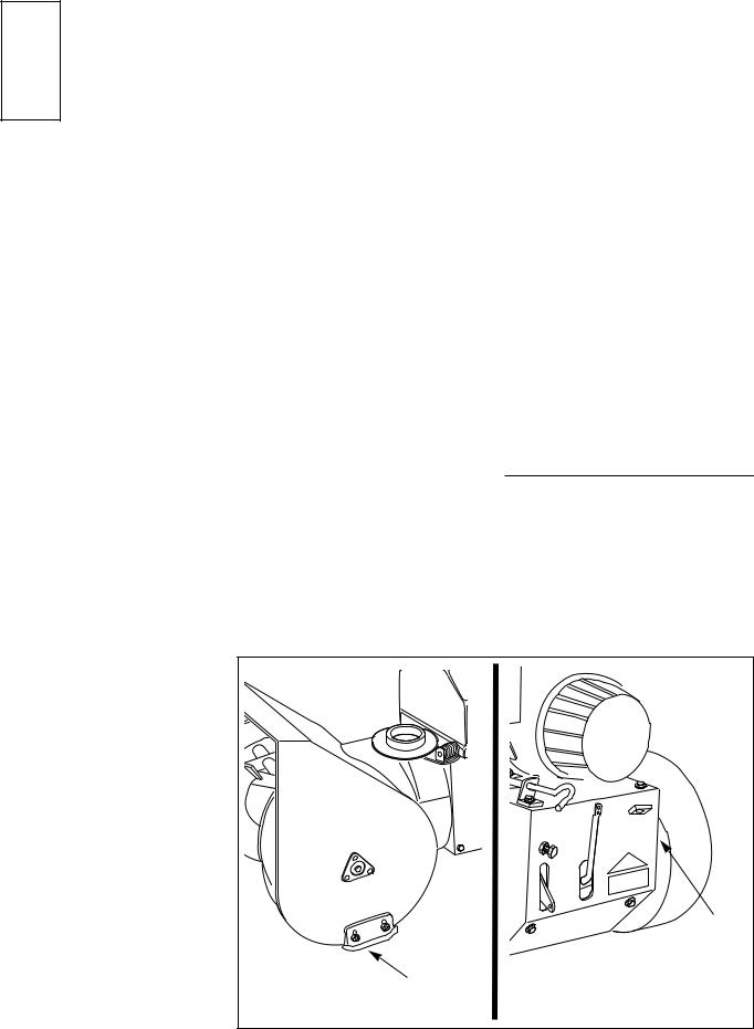
3.Remove the hex nut (A, Fig. 2-1) and the shipping strap from the left side skid shoe. Reinstall the hex nut, tightening it securely.
4.Remove the screw (B, Fig. 2-1) and the shipping strap from the rear cover on the right side of the unit. Reinstall the screw, tightening it securely.
5.The unit is heavy. Use caution and obtain the help of at least one assistant. Carefully remove the unit from the crate by rolling the unit off the platform. Park the unit on a clean, level surface.
D. Hardware Bag Contents
The hardware bag should contain the items listed below and shown in Fig. 2-2:
Ref. |
Description |
Qty. |
A |
Cable tie ...................................... |
3 |
B |
Hex hd. flange screw, 3/8-16 x 3/4 4 |
|
C |
Hex hd. screw, 1/4-20 x 3/4........... |
2 |
D |
Locknut, 1/4-20 ............................. |
2 |
E |
Phillips hd. screw, #10-24 x 3/8 ... |
2 |
F |
Locknut, #10-24 ............................ |
2 |
G |
Cotter pin ...................................... |
1 |
H |
*Shear bolt, 5/16-18 x 1-3/4 ......... |
2 |
I |
*Locknut, 5/16-18 ......................... |
2 |
J |
Ignition key .................................... |
2 |
--Grease Tube (not illustrated). For
maintenance use if required......... |
1 |
*These items are extra auger shear bolts and locknuts (if the auger catches a hard obstruction, the shear bolts are designed to break to prevent damage to the auger and other parts). See the “Maintenance” section for replacement steps.
(2) *7/16" wrenches
(2) *1/2" wrenches
(1) *9/16" wrench
(1) Phillips head screwdriver (medium)
(1) Needle-nosed pliers (medium)
(1) Automotive-type tire pressure gauge
(1) Funnel
(1)Clean, high-quality motor oil. Refer to the separate engine owner’s manual for the exact oil specifications and amount needed for your engine.
* Adjustable wrenches may be used.
IMPORTANT: Motor oil must be added to the engine crankcase before the engine is started. Follow the instructions in this “Assembly” section.
|
B |
A |
Remove Rear Shipping Strap. |
Fig. 2-1 |
|
8

Section 2: Assembly
IMPORTANT: Left and right sides of the unit are determined from the operator position, facing the direction of forward travel.
E. Install Handlebars
1.Cut the plastic cable ties securing the handlebar ends to the chassis and remove the handlebars. Remove the protective wrapping on the handlebars.
2.Attach the handlebars to the sides of the chassis as follows (use the four 3/8-16 x 3/4" hex flange screws supplied in hardware bag):
a.Install two screws in the upper mounting holes (C, Fig. 2-3) on each side. Leave screws loose enough to allow handlebar to pivot.
b.Install two screws (D) in the lower mounting holes.
c.Using light pressure, press down on the left side handlebar and tighten the two screws. Repeat on the right side handlebar.
3.There are four pre-installed screws (E, Fig. 2-3) on the inside of the handlebars that secure the control panel to the handlebars. Check each screw and tighten securely.
A |
|
J |
|
|
|
|
|
H |
|
Hardware shown full size. |
|
B |
|
|
C |
E |
G |
|
F |
|
D |
|
I |
|
|
|
Fig. 2-2 |
|
|
|
E |
|
|
|
E |
|
|
C |
|
|
D |
Fig. 2-3 |
|
|
9
Section 2: Assembly
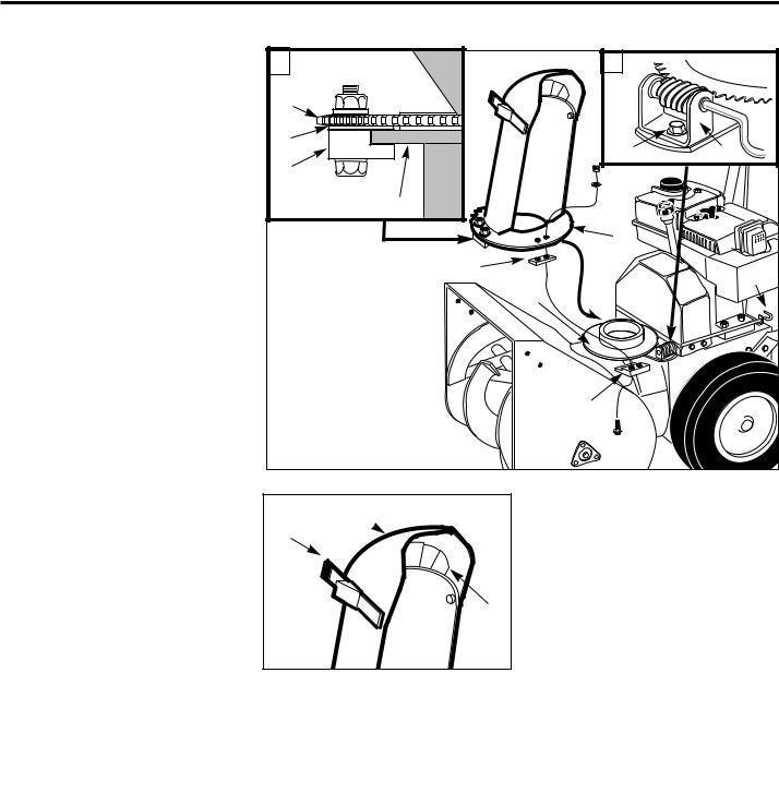
F. Install Discharge Chute
1.Remove the cardboard packing shield from the discharge chute mount opening.
2.Loosen (do not remove) the left and right side sets of plastic shims (G, Fig. 2-4, inset A) and plastic hold-down clips (H, Fig. 2-4, inset A) on the toothed flange (J) of the discharge chute assembly. Remove and save the remaining (front) hold-down clip, shim and mounting hardware.
3.From either side of the unit, slide the discharge chute onto the chute mounting flange (K), making sure that the plastic shims (G) are above the flange and the plastic hold-down clips
(H) are below the flange. Tighten the shim mounting hardware securely (if necessary, rotate the discharge chute to the right in order to tighten the left side shim and hold-down clip).
4.Hook the front hold-down clip (H) under the mounting flange (K) and place the front plastic shim (G) on top of the hold-down clip, between the top of the flange and the toothed chute flange. Using two 5/16" wrenches, secure with the screws, washers and locknuts.
5.Remove the plastic cable tie that secures the worm gear assembly (L, Fig. 2-4 inset B) to the mounting bracket.
6.Remove the washer and locknut from the screw (M, Fig. 2-4 inset B) in the worm gear assembly (L). Position the worm gear assembly on the mounting bracket as follows:
a. Engage the worm gear threads 1/2- way with the teeth on the flange of the discharge chute base (rotate chute as needed).
b. The length of the worm gear should be centered with the teeth on the flange of the discharge chute base.
c. Reinstall the washer and locknut on the screw (M) and tighten securely.
A |
B |
|
J |
|
|
G |
M |
L |
|
||
H |
|
|
|
K |
|
|
J |
|
|
(Front shim) G |
F |
|
|
|
|
K |
|
|
(Front hold- |
|
|
down clip) H |
|
Fig. 2-4 |
|
|
O 
P
N
Fig. 2-5
d.Turn chute control rod (F, Fig. 2-4) by hand to be sure the worm gear and discharge chute rotate freely, but with enough resistance to prevent free rotation of the discharge chute during snow removal operation. Readjust position of worm gear assembly as necessary.
7.Insert the flexible fingers on the plastic snow deflector (N, Fig. 2-5) inside the chute deflector cap (O). Close the deflector cap by pulling the lever (P) outward and moving the deflector cap down. Release the lever to secure the deflector cap in one of the discharge angle selector holes.
G. Attach Chute Control Rod
1.Remove the plastic cable tie that secures the auger drive control rod (AA, Fig. 2-6) to the right handlebar. Next, remove the plastic cable tie that secures the chute crank rod (short rod with plastic swivel blocks) to the auger drive control rod.
2.Pull the chute crank rod (Z, Fig. 2-6) up through the top of the control panel.
3.Attach the chute control rod sections (S and U, Fig. 2-6) as follows:
a.Insert the angled end of the chute control rod, (U, Fig. 2-6 inset) into the hole in the swivel block (V) that is attached to the end of the chute crank rod (S).
b.Insert a cotter pin (W) through the hole in the chute control rod (U) and spread the ends of the cotter pin.
4.Position the chute control support (Y, Fig. 2-7) against the underside of the handlebar console as shown. Secure the support with the two #10–24 x 3/8" Phillips pan head screws and #10–24 locknuts supplied.
10
 Loading...