


Warranty |
|
|
|
|
chance |
||||
|
|
Lite |
|
||||||
Registration.com/warranty |
|||||||||
|
|
|
today |
for |
a |
|
product! |
||
|
|
|
|
|
|
|
|||
|
|
|
|
|
|
|
|
||
|
online |
Tripp |
|
|
|
|
|||
Registerwin |
|
FREE |
|
|
|
|
|
|
|
a |
.tripplite |
|
|
|
|
|
|||
to |
www |
|
|
|
|
|
|
||
Owner’s Manual
Monitored PDU
Zero U (Vertical) Format
* 
*CE logo applies to models with IEC power inlet.
Important Safety Instructions
Installation
Features
Configuration and Operation
Technical Support
Warranty and Warranty Registration
Español
Français
2
2
6
8
8
9
10
19
1111 W. 35th Street • Chicago, IL 60609 USA 773.869.1234 • www.tripplite.com
Copyright © 2009 Tripp Lite. All rights reserved.
Important Safety Instructions
SAVE THESE INSTRUCTIONS
This manual contains instructions and warnings that should be followed during the installation, operation, and storage of this product. Failure to heed these instructions and warnings will void the product warranty.
•The PDU provides convenient multiple outlets, but it DOES NOT provide surge or line noise protection for connected equipment.
•The PDU is designed for indoor use only in a controlled environment away from excess moisture, temperature extremes, conductive contaminants, dust or direct sunlight.
•Do not connect the PDU to an ungrounded outlet or to extension cords or adapters that eliminate the connection to ground.
•The power requirement for each piece of equipment connected to the PDU must not exceed the individual outlet’s load rating.
•The total power requirement for equipment connected to the PDU must not exceed the maximum load rating for the PDU.
•Do not drill into or attempt to open any part of the PDU housing. There are no user-serviceable parts inside.
•Do not attempt to modify the PDU, including the input plugs and power cables.
•Do not attempt to use the PDU if any part of it becomes damaged.
•Do not attempt to mount the PDU to an insecure or unstable surface.
•Never attempt to install electrical equipment during a thunderstorm.
•Use of this equipment in life support applications where failure of this equipment can reasonably be expected to cause the failure of the life support equipment or to significantly affect its safety or effectiveness is not recommended. Do not use this equipment in the presence of a flammable anesthetic mixture with air, oxygen or nitrous oxide.
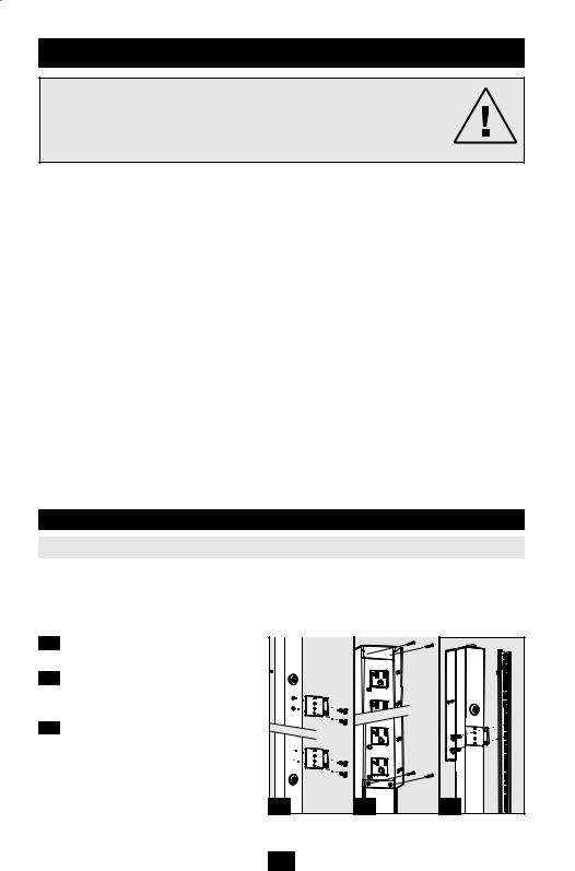
Installation
Mounting the PDU
Note: The illustrations may differ somewhat from your PDU model. Regardless of configuration, the user must determine the fitness of hardware and procedures before mounting. The PDU and included hardware are designed for common rack and rack enclosure types and may not be appropriate for all applications. Exact mounting configurations may vary. Screws for attaching the mounting brackets and cord retention shelf to the PDU are included. Use only the screws supplied by the manufacturer, or their exact equivalent (#6-32, ¼" flat head).
1-1 Attach the mounting brackets to the PDU.
1-2 (Optional) Attach the cord retention bracket(s) to the PDU.
1-3 Attach the PDU to a vertical rail in your rack or rack enclosure. (Use the mounting hardware that came with your rack or rack enclosure to attach the mounting brackets to the rail.) Attach the included mounting buttons to the PDU. Position the PDU as desired in the rack enclosure, align the buttons with the rack mounting slots, and slide the PDU into position.
1-1 |
1-2 |
1-3 |
2 |
|
|

Installation continued
Connecting the PDU
2-1 (Models with IEC power inlet only.) Select models have a detachable power cord. Attach the included power cord to the PDU by inserting the IEC connector A of the power cord into the IEC power inlet B located near the end of the PDU. Use the included bracket C to secure the power cord connection.
Note: Optionally, a user-supplied power cord can be attached to the PDU by connecting it to the IEC inlet. Do not attempt to attach a user-supplied power cord unless it is certified to be compatible with the input power source that will be used by the PDU.
2-2 (Optional - models with input plug adapter only.) Select models include an input plug adapter that converts the twist-lock input plug to a straight-blade input plug. Attach the input plug adapter A to the input plug B if you wish to plug the PDU into a compatible straightblade outlet.
2-3 Connect the input plug to a compatible AC power outlet. If the PDU does not have a circuit breaker, it should be provided with a branchrated over-current protection device that matches the rated amperage of the PDU.
Note: The AC power source should not share a circuit with a heavy electrical load.
2-4 Connect your equipment's input plugs A to the outlets B of the PDU. The digital load meter C displays the total connected equipment load in amps. (Select models provide additional load data. See the Features section for more information.)
Note: In order to minimize interference among connected devices, connect each device to the nearest PDU outlet and coil excess power cord length.
2-5 (Optional) If you attached the cord retention bracket(s), tie each equipment power cord to the retention bracket. Attach each cord to the retention shelf by looping the cord and securing it with one of the included cable ties A . Make sure that each cord can be unplugged from the PDU without removing the cable tie.
|
C |
|
A |
2-1 |
B |
|
|
|
A |
|
B |
2-2 |
2-3 |
B |
A |
C |
2-4 |
A |
2-5 |
3
 Loading...