


Tripp Lite World Headquarters:
1111 W. 35th Street
Chicago, IL 60609 USA
Customer Support:
1 (800) 420-9764
Hours: 8:00am-5:30pm CST Mon.-Fri.
www.ReliableUPS.com
Owner's Manual
IBM Network
Professional
700 RM UPS
Rackmount Intelligent Network
UPS System (120V)
ESPAÑOL: p. 7
FRANÇAIS: p. 14
Safety: |
p. 2 |
|
|
Installation: |
p. 3 - 4 |
|
|
|
|
|
|
|
Basic Operation: |
p. 4 - 6 |
|
|
|
|
|
|
|
Storage & Service: |
p. 6 |
|
|
|
|
|
|
|
Specifications: |
p. 6 |
|
|
|
|
Manufactured for, distributed through, and sold by Tripp Lite, official licensee for this product. IBM, the IBM logo trademark and the IBM trade dress are owned by International Business Machines Corporation and are used under license from IBM. IBM does not manufacture this product and provides no warranty or support for this product. Please call Tripp Lite Customer Support at 1(800)420-9764 for all questions, comments, service or support related to this product.
Copyright ©2000 Tripp Lite. All rights reserved.
1

Safety
This manual contains important instructions and warnings that should be followed during the installation, operation and storage of all Tripp Lite UPS Systems.
UPS Location Warnings
•Install your UPS indoors, away from excess moisture or heat, dust or direct sunlight.
•For best performance, keep the indoor temperature between 32° F and 104° F (between 0° C and 40° C).
•Leave adequate space around all sides of the UPS for proper ventilation.
UPS Connection Warnings
•Connect your UPS to a three-wire, grounded AC power outlet. Do not remove or modify the ground pin of the UPS's plug. Do not use two-prong adapters with the UPS's plug.
•Do not plug your UPS into itself; this will damage the UPS and void your warranty.
•If you are connecting your UPS to a motor-powered AC generator, the generator must provide clean, filtered computer-grade output.
Equipment Connection Warnings
•Do not use Tripp Lite UPS Systems for life support applications in which a malfunction or failure of a Tripp Lite UPS System could cause failure or significantly alter the performance of a life-support device.
•Do not connect surge suppressors to the output of your UPS. This may damage your UPS and will void both the surge suppressor and UPS warranties.
Battery Warnings
•Your UPS does not require routine maintenance. Do not open your UPS for any reason. There are no user-serviceable parts inside.
•Battery replacement must be performed by qualified service personnel. Because the batteries present a risk of electrical shock and burn from high short-circuit current, observe proper precautions. Unplug and turn off the UPS before performing battery replacement. Use tools with insulated handles and replace the existing batteries with the same number and type of new batteries (Sealed Lead-Acid). Do not open the batteries. Do not short or bridge the battery terminals with any object.
•The UPS batteries are recyclable. Refer to local codes for disposal requirements or, in the US only, call 1-800-SAV-LEAD (1-800-728-5323) for complete recycling information. Do not dispose of the batteries in a fire.
•Do not attempt to add external batteries unless your UPS is equipped with External Battery Connectors.
•Observe proper polarity when connecting replacement batteries. Only connect Negative (black) wires to Negative (black) terminals. Only connect Positive (red) wires to Positive (red) terminals.
•If a qualified service representative performs “hot-swap” battery replacement (when the UPS and connected equipment are turned ON) your UPS will not be able to provide battery backup in the event of a blackout because the batteries will be momentarily disconnected as they are exchanged.
2

|
Installation |
|
|
1 |
Install rack handles |
|
(supplied) and mount |
|
UPS in standard |
|
19 in. rack using |
|
standard rack hardware |
|
(user supplied). |
|
Install your UPS in the lowest rack position |
|
possible. |
2 |
Plug your UPS into |
|
an electrical outlet. |
Your UPS should occupy a 15-amp dedicated circuit.
3 |
Plug your equipment into |
|
your UPS. |
Your UPS is designed to support only computer equipment. Connecting household appliances, laser printers or surge suppressors is not recommended.
4 |
Turn your UPS ON. |
System Enable Switch |
|
|
Set the System Enable Switch to the |
|
|||
Located on Front Panel |
|
|||
|
“ENABLE” position. |
("I" = ENABLE; |
|
|
|
This switch activates the battery charger and |
"O" = DISABLE) |
|
|
|
microprocessor. |
|
|
|
|
The “ |
” light will flash until you engage the |
|
|
|
ON/Standby Switch to activate the “ON” |
|
|
|
|
mode. |
|
|
|
|
|
|
|
|
|
Engage the momentary ON/Standby |
|
|
|
|
|
|
||
|
Switch (UPS front panel) and release it |
ON/Standby Switch |
|
|
|
to activate the “ON” mode and supply |
Located on Front Panel |
|
|
|
power to the UPS receptacles. |
|
|
|
|
|
|
|
|
3
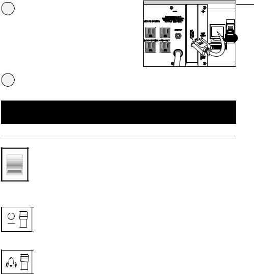
5 |
DB9 Port Connection |
|
–Optional–* |
Using Tripp Lite cable, connect your primary server’s DB9 port to the single DB9 port labeled “SMART” (which provides complete intelligent RS-232 communications).
* Serial port connections are optional. Your UPS will function properly without these connections.
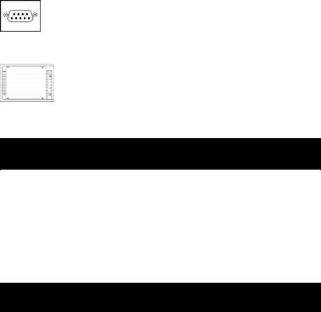
6 |
Load software and run the installation |
|
program appropriate for your operating system. |
Basic Operation
Switches
System Enable Switch
This switch activates the battery charger and intelligent microprocessor. Always leave it in the “ENABLE” position when your UPS is plugged in. Set the switch to “DISABLE” only if you store or ship your UPS (to reduce battery drain).
*Note: The “  ” light will flash until you engage the ON/Standby Switch to activate the “ON” mode (power ON at the UPS receptacles).
On/Standby Switch
This momentary switch controls power to the UPS receptacles. Engage it momentarily and release it to toggle between the “ON” mode (power ON at the UPS receptacles) and “Standby” mode (power OFF at the UPS receptacles).
Mute/Test Switch
Use this momentary switch to do two things:
Silence the blackout alarm
Engage this switch and release it. Note: when the battery is nearly depleted, the alarm resumes (and cannot be silenced) to alert you to immediately shut down connected equipment.
Test your UPS’s battery charge
Leave your connected equipment ON. With your UPS plugged in and completely turned ON, engage this switch; hold it there for 5 seconds and release it. The UPS will momentarily switch to battery to test its charge. The alarm will sound and the “  ” light may turn ON if your UPS fails a self-test and/or the UPS battery is less than fully charged. Let the UPS charge for 12 hours and perform a second self-test. If the light continues to stay on, contact Tripp Lite for service. CAUTION: Do not unplug your UPS to test its batteries. This will remove safe electrical grounding and may introduce a damaging surge into your network connections.
4

Indicator Lights
All Indicator Light descriptions apply when the UPS is plugged into a wall outlet and the System Enable Switch is turned ON.
This green light will shine constantly to indicate AC power is available at the receptacles. It will flash to indicate AC power is not available. (See “System Enable Switch” and “ON/Standby Switch” descriptions above.)
This multi-colored light displays 7 separate UPS battery charge conditions. It will turn from red (low) to yellow (medium) to green (full) to show you the level of battery charge. If the light is constant, then your UPS is operating from line power and the battery is charging. If the light is flashing, then your UPS is operating from battery power and the battery is discharging. When the light flashes red, close any files you are working on and shut down your computer.
Whenever your UPS is automatically correcting high or low AC line voltage, this green light will turn ON and the UPS will gently click. The more the UPS has to correct voltage, the more the green light will turn ON and the more the UPS will click. These are both normal, automatic operations of your UPS, and no action is required on your part.
This red light will turn ON if your UPS fails a self-test and/or the UPS battery is less than fully charged. Let the UPS charge for 12 hours and perform a second self-test. If the light continues to stay on, contact Tripp Lite for service.
This multi-colored light displays 4 separate UPS load conditions. It will turn from green (low) to yellow (medium) to red (high) as you connect equipment to show you the load level your UPS is supporting. When the light is red your UPS is supporting a load above 85% of its capacity. If the red light begins flashing, your UPS is severely overloaded. Remove overload immediately until light stops flashing.
Other UPS Features
AC Receptacles
The receptacles provide your connected equipment with AC line power during normal operation and battery power during blackouts and brownouts. They also protect your equipment against damaging surges and line noise. You can remotely reboot connected equipment by turning all of the receptacles OFF and ON at once using Tripp Lite UPS software. See software instructions for details.
5
“SMART” RS-232 Port
The RS-232 port connects your UPS to any workstation or server. Use with Tripp Lite software and included cable to monitor and manage network power and automatically save open files and shut down equipment during a blackout. This port uses RS-232 communications to transmit UPS and power conditions (Pin 7 = Transmit; Pin 8 = Common; Pin 9 = Receive). Contact Tripp Lite Customer Support for more information and a list of available SNMP, network management and connectivity products.
Battery Replacement Door
Under normal conditions, the original batteries in your UPS will last several years. Battery replacement should only be performed by qualified service personnel. Refer to “Battery Warnings” in the Safety section on page 2. When replacing batteries, qualified service personnel should follow this procedure: 1) turn UPS OFF; 2) remove the battery door located on the front panel; 3) pull batteries partially out of the case; 4) make a detailed sketch of the batteries and the polarity, color and connection of all
cables; 5) disconnect battery terminals; 6) dispose of used batteries; 7) reconnect replacement batteries exactly as original batteries were; 8) push batteries back into case and replace cover.*
* You may not receive full runtime until your replacement batteries have fully charged.
Storage & Service
Storage
Turn your UPS OFF: first, engage the ON/Standby Switch and release it to place your UPS in the “Standby” mode; then set the System Enable Switch to “DISABLE”; finally, disconnect the UPS power cord from the wall outlet. If you plan on storing your UPS for an extended period of time, recharge the UPS batteries once every three months. Follow steps #1 and #3 in the Installation section and allow the UPS to charge from 4 to 6 hours. If you leave your UPS batteries discharged for an extended period of time, they will suffer permanent loss of capacity.
Service
If returning your UPS to Tripp Lite, please carefully pack the UPS using the ORIGINAL PACKING MATERIAL that came with the unit. Enclose a letter describing the symptoms of the problem. If the UPS is within the 2 year warranty period, enclose a copy of your sales receipt.
Specifications
|
NP700RM |
Output Capacity (VA/Watts): |
700/450 |
Battery Runtime (Half Load/Full Load) Min.: |
28/12 |
Battery Recharge Time: |
2-4 hrs. |
Suggested Circuit: |
15 amp |
Approvals: |
UL, cUL, FCC Class B |
Input Voltage/Frequency (120V/60 Hz); On Line Input |
Voltage Range (87 - 140 Volts); Voltage-Regulated Output Voltage Range |
(120V +/- 9%); On Battery Output Voltage Range (120V +/- 5%); Output Waveform Line Mode (filtered sinewave); Output Waveform Battery Mode (PWM sine wave); AC Surge Suppression (exceeds IEEE 587 Cat. A & B standards); AC Noise Attenuation (>40 dB); AC Protection Modes (H to N, H to G, N to G).
FCC Radio/TV Interference Notice
Note: This equipment has been tested and found to comply with the limits for a Class B digital device, pursuant to Part 15 of the FCC Rules. Theselimitsaredesignedtoprovidereasonableprotectionagainstharmfulinterferenceinaresidentialinstallation.Thisequipmentgenerates, uses and can radiate radio frequency energy, and if not installed and used in accordance with the instruction manual, may causeinterference toradiocommunications. However,thereisnoguaranteethatinterferencewillnotoccurinaparticularinstallation.Ifthisequipmentdoescause harmful interference to radio or television reception, which can be determined by turning the equipment off and on, the user is encouraged to try to correct the interference using one or more of the following measures: reorient or relocate the receiving antenna; increase the separation betweentheequipmentandreceiver;connecttheequipmentintoanoutletonacircuitdifferentfromthatwhichthereceiverisconnected;consult the dealer or an experienced radio/television technician for help. The user must use shielded cables and connectors with thisproduct. Any changes or modifications to this product not expressly approved by the party responsible for compliance could void the user's authority to operatetheequipment.
The policy of Tripp Lite is one of continuous improvement. Specifications are subject to change.
6
 Loading...