


200210187 Smart 700-1000 RM1U Owner’s Manual 93-2102.qxd 11/1/2002 9:50 AM Page 1
Owner’s Manual
SmartPro® 1U Rackmount
120V Input/Output UPS Systems • Standby • Intelligent
Models: 750—1000 VA
Important Safety Instructions
Mounting
Connection
Basic Operation
Storage and Service
Battery Replacement |
10 |
Specifications |
11 |
Español |
13 |
1111 W. 35th Street Chicago, IL 60609 USA Customer Support: (773) 869-1234 • www.tripplite.com
Copyright ©2002 Tripp Lite. All rights reserved. SmartPro® is a registered trademark of Tripp Lite.
200210187 Smart 700-1000 RM1U Owner’s Manual 93-2102.qxd 11/1/2002 9:50 AM Page 2
Important Safety Instructions
SAVE THESE INSTRUCTIONS
This manual contains important instructions that should be followed during the installation, operation and storage of all Tripp Lite UPS Systems. Failure to heed these warnings will void your warranty.
UPS Location Warnings
•Install your UPS indoors, away from excess moisture or heat, dust or direct sunlight.
•For best performance, the ambient temperature near your UPS should be between 0º C and 40° C (between 32° F and 104° F).
•Leave adequate space around all sides of the UPS for proper ventilation. Do not obstruct its vents or fan openings.
UPS Connection Warnings
•The UPS contains its own energy source (battery). The output terminals may be live even when the UPS is not connected to an AC supply.
•Connect your UPS directly to a properly grounded AC power outlet. Do not plug your UPS into itself; this may damage the UPS.
•Do not modify the UPS’s plug. Do not use adapters that eliminate the UPS's connection to ground. Do not use extension cords between the UPS and the AC outlet. If necessary, a Tripp Lite surge suppressor may be used between the UPS and the AC outlet.
•If you are connecting your UPS to a motor-powered AC generator, the generator must provide filtered, frequency-regulated computer-grade output. Connecting your UPS to a generator will void its Ultimate Lifetime Insurance.
Equipment Connection Warnings
•Do not use Tripp Lite UPS Systems for life support applications in which a malfunction or failure of a Tripp Lite UPS System could cause failure or significantly alter the performance of a life-support device.
•Do not connect surge suppressors or extension cords to the output of your UPS. This may damage your UPS and will void both the surge suppressor and UPS warranties.
Battery Warnings
•Except for battery replacement, your UPS does not require routine maintenance. Do not open your UPS for any reason. There are no user-serviceable parts inside.
•Battery replacement must be performed by qualified service personnel. Because the batteries present a risk of electrical shock and burn from high short-circuit current, qualified service personnel should observe proper precautions: make sure the UPS is not in INVERT mode before performing battery replacement. Use tools with insulated handles and replace the existing batteries with the same number and type of new batteries (Sealed Lead-Acid). Do not open the batteries. Do not short or bridge the battery terminals with any object.
•Do not operate UPS without batteries except during hot-swap battery replacement.
•The UPS batteries are recyclable. Refer to local codes for disposal requirements or in the USA only call 1-800-SAV-LEAD (1-800-728-5323) for complete recycling information. Do not dispose of the batteries in a fire.
•Do not attempt to add external battery packs.
2
200210187 Smart 700-1000 RM1U Owner’s Manual 93-2102.qxd 11/1/2002 9:50 AM Page 3
Mounting
Matching Your Front Panel to Your Equipment
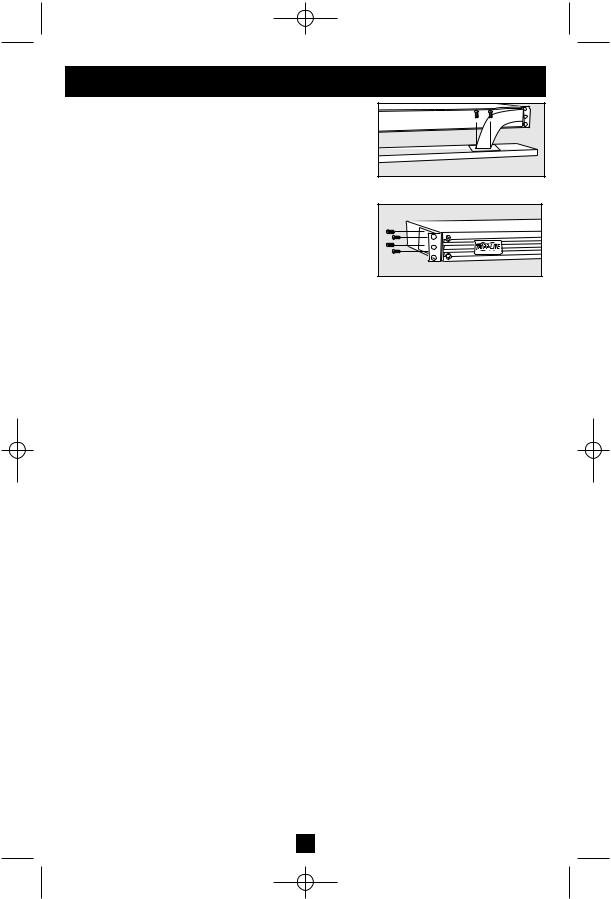
Your UPS ships with two front panels of different colors, one installed and one separate. If you want to swap your UPS’s front panel to better match the color of your other equipment, remove the installed front panel by first removing the four screws in its corners, then carefully removing the two screws that connect the UPS’s controls and LEDs to the inside of the front panel as shown in Figure 1. Connect the controls to the new front panel, then attach it to the UPS in place of the first.
Rackmount
Position brackets as shown in Figure 2 to serve as mounting ears for the UPS in your rack. Use 4 mounting screws to connect the UPS to each bracket. Mount the UPS in your rack with user-supplied screws and hardware appropriate to your rack. Have an assistant hold the UPS in position while mounting.
Desktop/Under-Monitor
Place on your desktop or under your computer monitor with the control and LED panel forward.
Figure 1—Panel Matching
Figure 2—Rackmount
3
200210187 Smart 700-1000 RM1U Owner’s Manual 93-2102.qxd 11/1/2002 9:50 AM Page 4
Connection
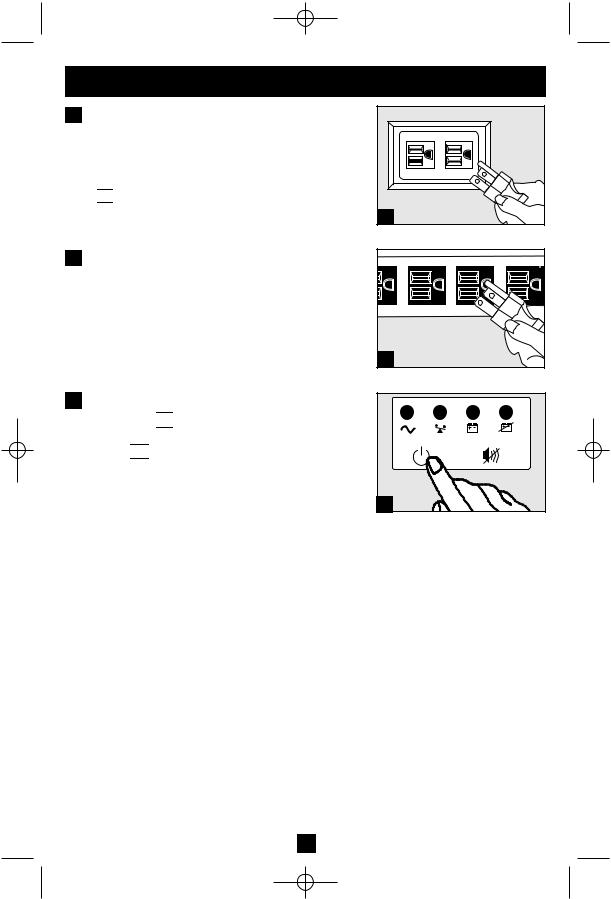
1 Plug your UPS into an electrical outlet.
Your UPS requires connection to a 15-amp dedicated circuit. Once your UPS is plugged in, the UPS will enter STANDBY mode. The fan will activate and the “ 

 ” (POWER) LED will begin flashing. The outlets will not be active until the UPS is turned ON.
1 |
2 Plug your equipment into your UPS.
Your UPS is designed to support only computer equipment. You will overload your UPS if you connect household appliances, laser printers or surge suppressors to the UPS’s Outlets.
3Turn your UPS ON
•Press the “ 

 ” (POWER) button
•Hold the button for a moment, until you hear a beep. The “ 

 ” (POWER) LED will stop flashing and be on constantly
•Release the button
Your UPS is now ON and its AC outlets are active.
2 |
3 |
4
200210187 Smart 700-1000 RM1U Owner’s Manual 93-2102.qxd 11/1/2002 9:50 AM Page 5
Connection optional
Your UPS will function properly without these connections.
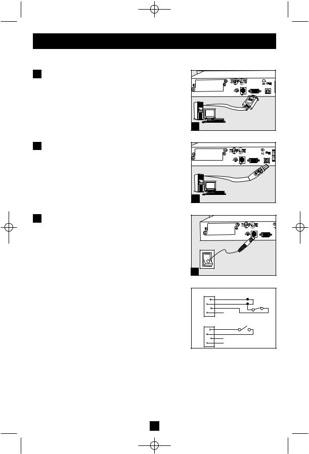
1 Serial Port Connection
Using the serial cable provided, connect a serial port from a computer to a serial port on your UPS. Install on the computer the Tripp Lite power protection software appropriate to its operating system.
2 USB Port Connection
Using the USB cable provided, connect a USB port from a computer to a USB port on your UPS. Install on the computer the Tripp Lite power protection software appropriate to its operating system.
|
|
|
SMART1000RM1U |
|
|
|
|
|
1155 NYCE |
|
|
|
SNMP CONFIG. |
|
ACC, SLOT |
NORM DELAY |
|
|
|
|
EPO |
1 |
2 |
|
|
SEE MANUAL |
|||
1 |
|
|
|
|
|
|
|
SMART1000RM1U |
|
|
|
|
1155 NYCE |
|
|
|
SNMP CONFIG. |
ACC, SLOT |
|
|
|
NORM DELAY |
EPO |
1 |
2 |
SEE MANUAL |
2
3 EPO Port Connection
Using the RJ-11 cable provided, connect the Emergency Power Off (EPO) port of your computer to a user-supplied normally closed or normally open switch according to the circuit diagram at the right. The EPO port is not a phone line surge suppressor; do not connect a phone line to this port.
|
|
SMART1000RM1U |
|
|
SNMP CONFIG |
ACC, SLOT |
|
|
NORM DELAY |
EPO |
1 |
SEE MANUAL |
3 |
|
|
|
OPTION 1: USER SUPPLIED NORMALLY CLOSED SWITCH |
|||
|
2 |
2-3 JUPMER |
|
RJ11 |
3 |
N.C. EPO SWITCH |
|
4 |
|||
PLUG |
|||
|
|||
|
5 |
|
|
|
NO CONNECTION |
||
OPTION 2: USER SUPPLIED NORMALLY OPEN SWITCH |
|||
|
2 |
N.O. EPO SWITCH |
|
RJ11 |
3 |
|
|
4 |
|
||
PLUG |
NO CONNECTION |
||
|
5 |
||
EPO Circuit Diagrams
5
200210187 Smart 700-1000 RM1U Owner’s Manual 93-2102.qxd 11/1/2002 9:50 AM Page 6
Basic Operation
Buttons (Front Panel)
Use the POWER button to switch your UPS between its four modes of operation.
OFF: No indicator lights are on. The UPS is completely shut down for storage or shipping. If the UPS is connected to AC power, it will start up in STANDBY mode. If the UPS is not connected to AC power and the POWER button is pressed for two seconds, the UPS will “cold start” into INVERT mode.
STANDBY: The “ 

 ” light is flashing. The UPS is receiving AC power and using it to charge its internal batteries, but its outlets are not active. Pressing the POWER button while the UPS is in STANDBY will put the UPS in the ON mode. Unplugging the UPS or cutting AC power while the UPS is in STANDBY will put the UPS in the OFF mode.
ON: The “

 ” light is on. The UPS is receiving AC power, charging its batteries and delivering power to connected equipment. Pressing the POWER button while the UPS is ON will put the UPS in STANDBY mode. If AC power is lost while the UPS is ON (i.e. a blackout occurs), the UPS will switch into INVERT mode.
INVERT: The “ 
 + –
+ – 
 ” light is flashing. The UPS is powering connected equipment from battery backup. If AC power is restored, the UPS will switch to the ON mode. Pressing the POWER button while the UPS is in INVERT will put the UPS into the OFF mode. If the UPS is in INVERT and its batteries are drained, the UPS will switch to the OFF mode until AC power is restored, then switch to the ON mode.
Use the MUTE/TEST button to do two things: |
SILENCE ALARM: Your UPS has three alarms. The first, the INVERT alarm, |
emits four short beeps every ten seconds when the UPS is in INVERT mode, |
to warn you that AC power has failed. The second, the OVERLOAD alarm, |
emits short, rapid beeps when the UPS is in INVERT mode if the total power draw |
of connected equipment exceeds the UPS’s output capacity, to warn you to |
reduce the load. The third, the LOW BATTERY alarm, emits a constant beep |
when the UPS is in INVERT mode and its batteries are very nearly depleted, to warn |
you that connected equipment must shut down. To silence the INVERT or |
OVERLOAD alarms, press the MUTE/TEST button. The LOW BATTERY |
alarm will only stop when the UPS switches to the OFF or ON mode. |
SELF-TEST BATTERIES AND ALARMS: If your UPS is in the ON mode and has a load connected, you may test its batteries by pressing the MUTE/TEST button for two seconds. The UPS will switch to INVERT mode for several seconds. Normally, the INVERT alarm (four short beeps) will sound, indicating that the system is working properly. If the OVERLOAD alarm (short, rapid beeps) sounds, reduce the load on the UPS. If the LOW BATTERY alarm (a constant beep) sounds, your UPS’s batteries may need replacing or they may simply be less than fully charged. Let the UPS charge for 12 hours, then perform a second self-test. If the LOW BATTERY alarm sounds again, contact Tripp Lite for service. Do not unplug your UPS to test its batteries, or you will remove safe electrical grounding and may introduce a damaging surge into your network connections.
6
200210187 Smart 700-1000 RM1U Owner’s Manual 93-2102.qxd 11/1/2002 9:50 AM Page 7
Basic Operation continued
Indicator Lights (Front Panel)
All Indicator Light descriptions apply when the UPS is plugged into a wall outlet and turned ON.
POWER: Lights green when the UPS is receiving AC power. Illuminates constantly when the UPS is in the ON mode, indicating that batteries are charging and connected equipment is receiving filtered AC power. Flashes while in STANDBY mode to indicate that batteries are charging but connected equipment is not receiving power.
|
|
|
|
|
|
|
|
BATTERY CHARGE: This multicolored light displays 6 separate UPS battery |
|
|
|
|
|
|
|
|
charge conditions. It will turn from red (low) to yellow (medium) to green (full) |
|
+ |
– |
|
to show you the level of battery charge. If the light is constant, your UPS is in |
||||
|
|
|
|
|
|
|
|
|
|
|
|
|
|
|
|
|
the ON or STANDBY mode, operating from line power, and the battery is |
|
|
|
|
|
|
|
|
charging. Whenever this light is flashing, your UPS is in the INVERT mode |
|
|
|
|
|
|
|
|
(operating from battery) and its battery is discharging. If the light is flashing |
|
|
|
|
|
|
|
|
|
|
|
|
|
|
|
|
|
red, your UPS battery is running out of power; you should save files and shut |
|
|
|
|
|
|
|
|
down your equipment immediately. |
|
|
|
|
|
|
|
|
OUTPUT LOAD: This multicolored light shows how heavy your UPS’s load |
|
|
|
|
|
|
|
|
|
|
|
|
|
|
|
|
|
is. Steady green indicates a light load, steady yellow a medium load. When the |
|
|
|
|
|
|
|
|
light is red, your UPS is supporting a load above 85% of its capacity. If the red |
|
|
|
|
|
|
|
|
light begins flashing, then your inverter is severely overloaded. Immediately |
|
|
|
|
|
|
|
|
remove load from the UPS until the light stops flashing. |
REPLACE BATTERY: Lights red if your UPS’s self-test (initiated with the
MUTE/TEST Switch) reveals a low battery charge or internal fault. If this light
+turns on, let the UPS charge for 12 hours then perform a second self-test. If the
–light stays on, contact Tripp Lite for service.
7
200210187 Smart 700-1000 RM1U Owner’s Manual 93-2102.qxd 11/1/2002 9:50 AM Page 8
Basic Operation continued
Other UPS Features (Rear Panel)
AC Receptacles
Your UPS features 15-amp AC outlets. These output receptacles provide your connected equipment with AC line power during normal operation and battery power during blackouts and brownouts. The UPS protects equipment connected to these receptacles against damaging surges and line noise. If you have a network connection to your UPS, you can remotely reboot connected equipment by turning the receptacles OFF and ON using Tripp Lite UPS software. Select models also feature a specially labeled “Load Control” receptacle that can be turned ON and OFF independently of the other receptacles using Tripp Lite UPS software. See software instructions for details.
Smart DB9 Serial Port
Your UPS features a DB9 port that may be used to connect the UPS to a DB9 port on any workstation or server. It uses RS-232 protocol to communicate UPS status and power conditions. Use with Tripp Lite cabling and PowerAlert Software to remotely monitor and manage power and automatically save open files and shut down equipment during a blackout. See Connection section.
Smart USB Port
Your UPS has a USB port that may be used to connect the UPS to a USB port on any workstation or server. It uses USB protocol to communicate UPS status and power conditions. Use with Tripp Lite cabling and PowerAlert Software to remotely monitor and manage power and automatically save open files and shut down equipment during a blackout. See Connection section.
EPO (Emergency Power Off) Port
Your UPS features a EPO port that may be used to connect the UPS to a switch to enable emergency inverter shutdown. See Connection.
SNMP Accessory Slot
Remove the small cover panel from this slot to install optional accessories to remotely monitor and control your UPS. Refer to your accessory’s manual for installation instructions. Contact Tripp Lite Customer Support at (773) 869-1234 for more information, including a list of available SNMP, network management and connectivity products.
Ground Lug
Use this to connect any equipment that requires a chassis ground.
8
 Loading...