


Warranty
ELECTRONIC AIR CLEANER LIMITED THREE-YEAR WARRANTY
This limited warranty covers Trion Residential Type Electronic Air Cleaners, excluding ductwork, wiring and installation. Trion warrants that all new Trion Electronic Residential Air Cleaners are free from defects in material and workmanship under normal, noncommercial use and service. Trion will remedy any such defects if they appear within 36 months from the date of original installation as evidenced by Proof of Purchase from an Authorized Trion Dealer, subject to terms and conditions of the Limited Three-Year Warranty stated below:
1.THIS LIMITED THREE-YEAR WARRANTY IS GRANTED BY CARECO, 415 WABASH AVE., P.O. BOX 200, EFFINGHAM, IL 62401.
2.This warranty shall extend only to any noncommercial owner who has purchased the residential Electronic Air Cleaner other than for purposes of resale.
3.All components are covered by this limited warranty except expendable items such as charcoal filters.
4.If within the warranty period, any Trion residential Electronic Air Cleaner unit or component requires service, it must be performed by a competent heating and or air conditioning contractor (preferably the installing contractor). CareCo will not pay shipping charges or labor charges to remove or replace such defective parts or components. If the part or component is found by inspection to contain such defective material and workmanship, it will be either repaired or exchanged free of charge at CareCo’s option, and returned freight collect.
5.In order to obtain the benefits of this limited three-year warranty, the owner must notify the dealer or distributor in writing or by phone, of any defect within 30 days of its discovery. If after reasonable time you have not received an adequate response from the dealer or distributor, notify in writing, by phone, or email: CareCo Warranty, 415 Wabash Avenue Effingham, IL 62401 or e:mail to: fiaqcustomerservice@fedders.com
6.This limited warranty does not apply to any part or component that is damaged in transit or when handling, has been subject to misuse, neglect or accident, has not been installed, operated and serviced according to Fedders Unitary Product’s instruction, has been operated beyond the factory rated capacity, or altered in any such way that its performance is affected. There is no warranty due to neglect, alteration or ordinary wear and tear. Fedders Unitary Product’s liability is limited to the replacement of defective parts or components and does not include the payment cost of labor charges to remove or replace such defective parts.
7.CARECO WILL NOT BE RESPONSIBLE FOR LOSS OF USE OF ANY PRODUCT, LOSS OF TIME, INCONVENIENCE, OR ANY OTHER INDIRECT, INCIDENTAL OR CONSEQUENTIAL DAMAGES WITH RESPECT TO PERSON OR PROPERTY, WHETHER AS A RESULT OF BREACH OF WARRANTY, NEGLECT OR OTHERWISE. SOME STATES DO NOT ALLOW THE EXCLUSION OR LIMITATION OF INCIDENTAL OR CONSEQUENTIAL DAMAGES, SO THE LIMITATION OR EXCLUSION IN THE PRECEDING SENTENCE MAY NOT APPLY TO YOU.
8.THIS WARRANTY GIVES YOU SPECIFIC RIGHTS, AND YOU MAY ALSO HAVE OTHER RIGHTS WHICH VARY FROM STATE TO STATE.
9.Any warranty (express, implied or statutory), representation, or guarantee other than those set forth herein, shall expire at the expiration date, of this express limited warranty. SOME STATES DO NOT ALLOW LIMITATIONS ON HOW LONG AN IMPLIED WARRANTY LASTS, SO THE LIMITATION IN THE PRECEDING SENTENCE MAY NOT APPLY TO YOU.
10.Fedders Unitary Products reserves the right to make changes in the design and material of its products without incurring any obligation to incorporate such changes in units completed on the effective date of such a change.
CareCo
415 Wabash Ave., P.O. Box 200, Effingham, IL 62401,
Phone: 1-866-829-2440
email: fiaqcustomerservice@fedders.com
HE Plus 1400
HE Plus 2000
Duct Mount
Electronic Air Cleaner
Installation • Operation • Maintenance
 CAUTION:
READ INSTALLATION, OPERATION, AND MAINTENANCE INSTRUCTIONS CAREFULLY FOR SAFE OPERATION.
EXERCISE EXTREME CAUTION WHEN WORKING WITH ELECTRICITY.
155587-001 07-04
26
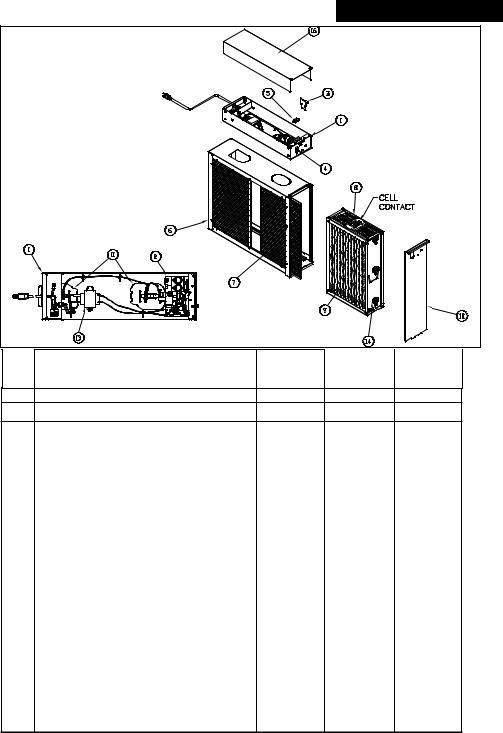
Table of Contents |
|
Introduction ...................................................................................... |
1 |
Unit Components.............................................................................. |
2 |
Operation .......................................................................................... |
3 |
1) Regular Dusting & “White Dust” ...................................... |
3 |
2) Ozone .................................................................................. |
3 |
3) High Altitude Operation.................................................... |
4 |
Maintenance of Your Electronic Air Cleaner .................................. |
5 |
1) Washing the Cells and Pre-filter(s).................................... |
5 |
2) Replacing the Ionizer Wires .............................................. |
6 |
3) Cleaning the Air Flow Sensor (AFS) .................................. |
6 |
Common Questions & Answers........................................................ |
7 |
Common Troubleshooting Techniques............................................ |
9 |
Unit Dimensions................................................................................ |
10 |
HVAC INSTALLATION INSTRUCTIONS .................................................... |
11 |
(for use by authorized HVAC contractors only) |
|
Technical Specifications .................................................................... |
11 |
Installation Considerations .............................................................. |
12 |
Application ............................................................................ |
12 |
Installation Requirements .................................................... |
12 |
Air Conditioning .................................................................... |
12 |
Evaporative Humidifiers........................................................ |
12 |
Atomizing Humidifiers .......................................................... |
13 |
Sheet Metal Installation ........................................................ |
13 |
Transitions .............................................................................. |
13 |
Outdoor Air............................................................................ |
13 |
Turning Vanes ........................................................................ |
13 |
Location Selection ............................................................................ |
14 |
Typical Mounting Positions .............................................................. |
15 |
Mechanical Installation .................................................................... |
16 |
Electrical Installation ........................................................................ |
18 |
System Checkout .............................................................................. |
19 |
Troubleshooting................................................................................ |
20 |
Air Flow Sensor ...................................................................... |
20 |
Primary Circuit ...................................................................... |
21 |
Secondary Circuit – Ionizing-Collecting Cell ........................ |
22 |
Secondary Circuit – Power Supply ........................................ |
23 |
Unit Diagram & Parts List ...................................................................... |
25 |
Warranty ................................................................................................ |
26 |
Parts List
Ref. Description |
HE Plus 1400 |
HE Plus 1400 |
HE Plus 2000 |
No. |
(16” x 25”) |
(20” x 20”) |
(20” x 25”) |
1 Power Tray Assembly 120/50-60/1 |
455578-001 |
455578-005 |
455578-001 |
1b Power Tray Assembly 240/50-60/1 |
455578-008 |
455578-007 |
455578-008 |
2 |
High Frequency Power Supply* |
348818-001 |
348818-001 348818-001 |
|
3 |
Electronic Air Flow Sensor* |
248090-001 |
248090-001 248090-001 |
|
4 |
On/Off switch* |
138586-001 |
138586-001 138586-001 |
|
|
|
|
|
|
5 |
Interlock Switch* |
242404-001 |
242404-001 242404-001 |
|
|
|
|
|
|
6 |
Cabinet Assembly |
355586-102 |
355586-301 355586-101 |
|
|
|
|
|
|
7 |
Pre-Filter (2 req.) |
123324-005 |
123324-007 123324-004 |
|
8 |
Cell, Ionizing-Collecting (2 req.) |
441730-101 |
441729-102 441729-101 |
|
9 |
Ionizing Wire Assembly |
220110-020 |
220110-029 220110-029 |
|
|
|
(13 req.) |
(10 req.) |
(13 req.) |
|
|
|
|
|
10 |
Front Panel Assembly |
355588-004 |
355588-019 355588-002 |
|
11 |
Contact Board Assembly (2 req.)* |
345109-001 |
345109-001 345109-001 |
|
12 |
Charcoal filter (optional, not shown) |
227833-003 |
227833-006 227833-004 |
|
13 |
Step-down Transformer 120V to 24VAC* |
239071-008 |
239071-008 239071-008 |
|
13a |
Step-down Transformer 240V to 24VAC * |
239071-011 |
239071-011 239071-011 |
|
|
|
|
|
|
14 |
Insulator (6 req. per cell) |
246287-001 |
246287-001 246287-001 |
|
|
|
|
|
|
15 |
Cell Key (not shown) (1 req.) |
143839-001 |
143839-001 143839-001 |
|
|
|
|
|
|
16 |
Power Tray Cover |
255575-001 |
255575-011 |
255575-001 |
*Component of Power Tray Assembly
25

Troubleshooting
For Qualified HVAC
Installer Only
10.If no voltage is present, remove the second cell. Install cell number one and measure voltage as described in step #7. If voltage is present, the second cell, which is now out of the cabinet, is shorted. Refer to COMMON TROUBLESHOOTING TECHNIQUES (pg. 9).
11.If no voltage is present, remove both IonizingCollecting Cells and measure the power supply output. While depressing the safety interlock switch lever, touch the end of the high voltage probe to either the front or rear contact board assembly. The meter should read 6.2 KVDC or higher.
12.If no voltage is present, check the transformer. Set the Multimeter for reading AC voltage at 200 volt full scale and attach meter test leads to the junction of the transformer secondary leads and the circuit board. The meter should read 24 volts +/– 4 volts.
13.If there is no voltage from the transformer, replace the transformer and power supply board.
Introduction
INTRODUCTION
This Electronic Air Cleaner is a two-stage electrostatic precipitator. The air cleaner is designed to remove airborne particulates, including dust, dirt, smoke, pollen, virus, spores, bacteria, and mold from indoor air.
Air movement through the unit is provided by the heating, air conditioning or ventilating system blower. As dirty air enters the air cleaner, the air passes through Metal Mesh Pre-filters. The Prefilters prevent lint, pet hair and other large particulates from entering the air cleaner. It is important that these filters be in place to prevent excessive dirt loading of the air cleaner Ionizing-Collecting Cells. These filters extend the time interval between scheduled maintenance of the air cleaner, which allows the Ionizing-Collecting Cells to provide clean air for a longer period between washings.
The pre-filtered air then passes through a two-stage Electronic Air Cleaner. In the first stage, all airborne particulate, even submicron size, are electronically charged (positive) as they pass through the ionizer section. The ionizer field is a result of a corona discharge emanating from the fine, tightly strung wires suspended between two adjacent flat plates. In the second stage, the charged particulate passes through an intense electrical field established between alternately charged and grounded parallel collector plates. Here, the charged (positive) particulate is attracted to the ground (negative) plates and removed from the air stream.
Measuring Voltage at Ionizing
Collecting Cell
Measuring Voltage at Contact
Board Assemblies
24 |
1 |
|
Unit Components
Cabinet
Mounts to existing ductwork; houses the Ionizing-Collecting Cells and Pre-filters.
Ionizing-Collecting Cells
Collect the dust, dirt and other particulates in the air. They contain the ionizing and collecting sections. The cells must be installed with the ionizing wires on the air intake side. A spring contact is located on the top of each cell and must be in the position to make contact with the contact board assemblies on the bottom of the Power Tray Assembly.
Pre-filters
Trap large particulates before they enter the Ionizing-Collecting Cell.
Power Tray Assembly
Contains the indicating lights, solid-state power supply, contact boards and electrical controls including the ON/OFF switch and safety interlock switch. A power cord at the rear of the 120 volt Power Tray allows the unit to be connected to a standard 120 volt outlet. A wiring compartment is provided on all models at the rear of the Power Tray allowing the option to permanently wire the unit directly to the HVAC System Control.
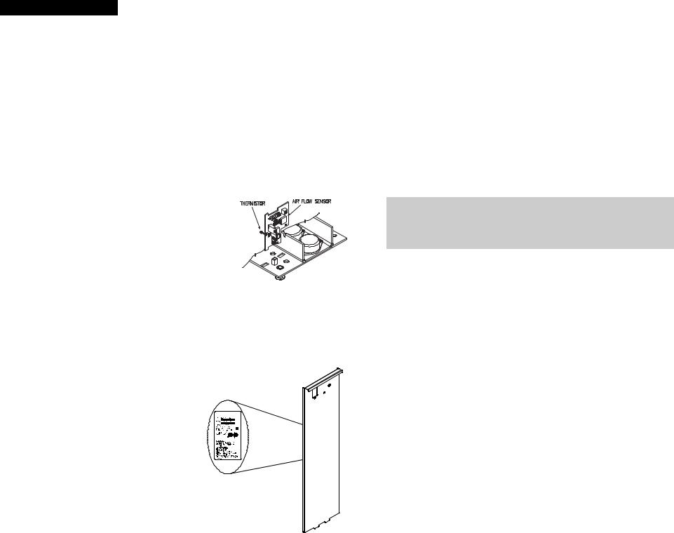
Air Flow Sensor (AFS)
Controls the operation of the unit by sensing the movement of air within the duct. This helps to reduce power usage.
The AFS is designed to provide an efficient and reliable method of controlling the operation of the air cleaner when
the installer is unable to wire the unit directly into the HVAC System Blower Control Circuit. The AFS utilizes a thermistor, which when electrically powered, heats up to approximately 130° F. The AFS stabilizes at this temperature and while the
HVAC System Blower is in operation, air flows through the ductwork, creating a vacuum effect that pulls cooler air over the hot surface of the thermistor. This air movement cools down the thermistor which allows the AFS to register that the HVAC System blower is moving air and the Electronic Air Cleaner must be powered to provide air cleaning.
Air Cleaner Model Identification
The model number and part number for your Electronic Air Cleaner can be found on the data label located on the inside of the Front Panel Assembly.
|
Troubleshooting |
|
|
|
For Qualified HVAC |
SECONDARY CIRCUIT POWER SUPPLY |
Installer Only |
|
If the Red CELL ENERGIZED light remains out with the Ionizing-Collecting Cells removed from the cabinet, the power supply is defective. Specific problems in the Power Tray Assembly can be isolated by using a Multimeter and High Voltage Probe to check the output voltages.
To check the secondary circuit, a high voltage meter is required. See the section entitled RECOMMENDED SERVICE TOOLS (pg. 20). To check for proper operation, it is imperative that the procedure be followed as outlined below:
1.Make sure the HVAC system is operating, the air cleaner ON/OFF switch is ON, and air cleaner input voltage is correct (120V, 50-60Hz for 120V units and 240V, 50-60Hz for 240V units).
2.Remove Front Panel Assembly from air cleaner.
3.Remove Power Tray Assembly Cover.
4.Check the high voltage contact board assembly for damage or carbon tracking.
 CAUTION:
The cell contacts must be visually checked for corrosion, excessive dirt build-up, and electrical arc tracking (Carbon path from stainless steel spring to grounded metal). Clean or replace as required.
5.Replace both Ionizing-Collecting Cells in the air cleaner cabinet.
6.Make test connections from the High Voltage Probe to the Multimeter in accordance with the probe’s instruction manual. The Multimeter should be set for reading DC voltage at 20 volt full scale.
7.Attach the High Voltage Probe ground lead to the air cleaner cabinet. While depressing the safety interlock switch lever, touch the ionizer wire support with end of the High Voltage Probe. The meter reading should be 6.2 kVDC + .2 kVDC.
8.If no voltage is measured, remove the first Ionizing-Collecting cell and check the second cell by repeating step #7. The meter should read 6.2 kVDC + .2 kVDC.
9.If proper voltage is measured, the first cell is shorted. Refer to COMMON TROUBLESHOOTING TECHNIQUES (pg. 9).
2 |
23 |
|
Troubleshooting
For Qualified HVAC
Installer Only
SECONDARY CIRCUIT
IONIZING-COLLECTING CELL
The cells are electrically energized through a contact terminal located at the top center of each cell. The ionizing wires and alternating collector plates are electrically charged while the interleaving plates are grounded.
If the space between the charged and grounded plates is bridged with conductive or semi-conductive material, a short circuit develops. The bridging or short may be caused by damaged plates, or foreign material lodged between/on the components. Since the cell should be periodically removed from the unit to wash away collected dirt, it is susceptible to physical damage. The cell also contains the ionizing wires, which have been designed, due to their function, with minimal structure support and are susceptible to breakage. Short circuit issues related to dirty or damaged Ionizing-Collecting Cells are readily identified by the lack of illumination of the Red CELL ENERGIZED light and quickly identified and isolated by a simple procedure.
To determine if a short circuit condition exists in one or both IonizingCollecting Cell(s), turn the Electronic Air Cleaner OFF. Remove both IonizerCollecting Cells from the cabinet. Re-position the Front Panel Assembly to the cabinet, turn ON/OFF switch ON and ensure HVAC system blower is operating.
The Green INPUT POWER light should illuminate. If the Red CELL ENERGIZED light illuminates, an electrical short circuit exists in one or both of the Ionizing-Collecting Cells. Replace the cells, one at a time, to determine which cell has the short circuit. The Red CELL ENERGIZED light will not illuminate if a short circuit condition is detected.
Most short circuit troubles in the cell can be visually detected and corrected. Refer to COMMON TROUBLESHOOTING TECHNIQUES (pg. 9).
NOTICE:
The Ionizing-Collecting Cells are not designed for field repair. Ionizing wires and insulators can be field replaced; however, it is not recommended that you attempt to replace other cell components (i.e. collecting plates, end plates, ionizer wire supports).
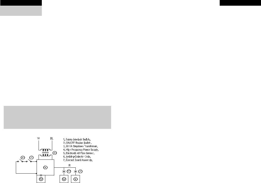
Circuit Diagram
Operation
Regular Dusting and “White Dust”
Your new Electronic Air Cleaner will efficiently clean and filter your household air. It will not eliminate the need for regular dusting of your furniture and belongings. Duct-mounted air cleaners can only clean air that reaches the air cleaner. Therefore, if the particulates are not being carried to the air cleaner in the air stream, the air cleaner cannot remove them from your home.
Occasionally a “white dust” may be noticed in bedrooms or newly furnished rooms. This is mainly composed of lint which, because it is heavier than other particulates, settles before it reaches your unit. This “white dust” is not mixed with airborne dirt particles, therefore, it is clean and has no staining or soiling properties. Running the furnace blower continuously, day and night, will help reduce this from occurring.
Ozone
Under normal operating conditions, all Electronic Air Cleaners produce minute quantities of ozone as an incidental by-product. In fact, all electronic products, such as televisions, cordless telephones and refrigerators, produce some amount of ozone. The average homeowner can detect the smell of ozone concentrations as low as 25 to 100 ppb (parts per billion). The design of this unit has been tested and ozone production is approximately half of the published permissible limits established by the Environmental Protection Agency. These limits recommend that the concentration of indoor ozone not exceed 50 ppb. Ozone is not harmful in these concentrations. In fact, the ozone level in major cities can sometimes reach as high as 100 ppb on a summer day. The addition of optional charcoal after-filters can help reduce the smell of ozone generated by the air cleaner.
Normally, a new unit will produce more ozone than one that has been in operation for several weeks. This is due to sharp corners or manufacturing burrs on the Ionizing-Collecting Cell Plates and is normal. As the Electronic Air Cleaner arcs and zaps, the voltage is vaporizing these areas and tends to round them off. This is part of the breaking-in period and the issue is self-correcting. Also, high-altitude locations can be more susceptible to noticing the presence of ozone.
An Ionizing-Collecting Cell that has been damaged or bent (the designed spacing between electrically-charged and ground components has been decreased) may also produce an abnormal amount of ozone.
22 |
3 |
|
 Loading...