


8 10/100TX + 2 10/100/1000T/Mini-GBIC
Combo with 8 PoE Injector Industrial Switch
User Manual
SISPM1040-182D
Version 1.01
October, 2009
Transition Networks SISPM1040-182D
Revision History
Document |
|
Date |
|
|
Revision |
|
|
Initials |
|
Release |
|
|
|
|
|
|
|||
|
|
|
|
|
|
|
|
|
|
|
|
|
|
|
|
|
|
|
|
1.00 |
|
Oct 31, 2008 |
|
First release |
|
A.E.F |
|||
|
|
|
|
|
|
|
|||
1.01 |
|
Oct 21, 2009 |
|
Corrections |
|
A.E.F |
|||
|
|
|
|
|
|
|
|
|
|
Technical Support: 1-800-260-1312 |
International: 00-1-952-941-7600 |

Transition Networks |
SISPM1040-182D |
Notice
The contents of this manual are based on the table below listing firmware version, kernel version, and hardware version. If the switch functions are different from the description of the manual, please contact the local sale dealer for more information.
|
|
|
|
|
Firmware Version |
V1.00 |
|
|
|
|
|
|
Kernel Version |
V1.56 |
|
|
|
|
|
|
Hardware Version |
---------- |
|
|
|
|
|
|
|
|
|
Technical Support: 1-800-260-1312 |
International: 00-1-952-941-7600 |
Transition Networks |
SISPM1040-182D |
FCC Warning
This Equipment has been tested and found to comply with the limits for a Class-A digital device, pursuant to Part 15 of the FCC rules. These limits are designed to provide reasonable protection against harmful interference in a residential installation. This equipment generates, uses, and can radiate radio frequency energy. It may cause harmful interference to radio communications if the equipment is not installed and used in accordance with the instructions. However, there is no guarantee that interference will not occur in a particular installation. If this equipment does cause harmful interference to radio or television reception, which can be determined by turning the equipment off and on, the user is encouraged to try to correct the interference by one or more of the following measures:
Reorient or relocate the receiving antenna.
Increase the separation between the equipment and receiver.
Connect the equipment into an outlet on a circuit different from that to which the receiver is connected.
Consult the dealer or an experienced radio/TV technician for help.
CE Mark Warning
This is a Class-A product. In a domestic environment this product may cause radio interference in which case the user may be required to take adequate measures.
Technical Support: 1-800-260-1312 |
International: 00-1-952-941-7600 |

Transition Networks |
|
SISPM1040-182D |
|
Content |
|
|
|
Chapter 1 |
Introduction......................................... |
1 |
|
1.1 |
Hardware Features...................................... |
1 |
|
1.2 |
Software Features....................................... |
5 |
|
1.3 |
Package Contents....................................... |
8 |
|
Chapter 2 |
Hardware Description ........................ |
9 |
|
2.1 |
Physical Dimension..................................... |
9 |
|
2.2 |
Front Panel.................................................. |
9 |
|
2.3 |
Bottom View .............................................. |
10 |
|
2.4 |
LED Indicators........................................... |
11 |
|
Chapter 3 |
Hardware Installation ....................... |
13 |
|
3.1 |
Installation Steps....................................... |
13 |
|
3.2 |
DIN-Rail Mounting..................................... |
14 |
|
3.3 |
Wall Mount Plate Mounting ....................... |
16 |
|
3.4 |
Wiring the Power Inputs ............................ |
17 |
|
3.5 |
Wiring the Fault Alarm Contact ................. |
18 |
|
3.6 |
Cabling ...................................................... |
19 |
|
Chapter 4 |
Network Application......................... |
23 |
|
4.1 |
X-Ring Application..................................... |
25 |
|
4.2 |
Coupling Ring Application ......................... |
26 |
|
4.3 |
Dual Homing Application........................... |
27 |
|
4.4 |
Dual Ring Application................................ |
28 |
|
Chapter 5 |
Console Management ...................... |
29 |
|
5.1 |
Connecting to the Console Port ................ |
29 |
|
5.2 |
Pin Assignment ......................................... |
29 |
|
Technical Support: 1-800-260-1312 |
International: 00-1-952-941-7600 |
Transition Networks |
|
SISPM1040-182D-LR |
|
5.3 |
Login in the Console Interface................... |
30 |
|
5.4 |
CLI Management....................................... |
32 |
|
5.5 |
Commands Level ...................................... |
32 |
|
Chapter 6 |
Web-Based Management................. |
34 |
|
6.1 |
About Web-based Management................ |
34 |
|
6.2 |
Preparing for Web Management ............... |
34 |
|
6.3 |
System Login............................................. |
35 |
|
6.4 |
System Information ................................... |
36 |
|
6.5 |
IP Configuration......................................... |
37 |
|
6.6 |
DHCP Server............................................. |
39 |
|
6.7 |
TFTP ......................................................... |
43 |
|
6.8 |
System Event Log ..................................... |
46 |
|
6.9 |
Fault Relay Alarm...................................... |
52 |
|
6.10 |
|
SNTP Configuration ................................. |
53 |
6.11 |
|
IP Security ................................................ |
57 |
6.12 |
|
User Authentication .................................. |
59 |
6.13 |
|
Port Statistics ........................................... |
60 |
6.14 |
|
Port Control .............................................. |
62 |
6.15 |
|
Port Trunk................................................. |
64 |
6.16 |
|
Port Mirroring............................................ |
74 |
6.17 |
|
Rate Limiting ............................................ |
75 |
6.18 |
|
VLAN configuration .................................. |
77 |
6.19 |
|
Rapid Spanning Tree ............................... |
87 |
6.20 |
|
SNMP Configuration................................. |
91 |
6.21 |
|
QoS Configuration.................................... |
97 |
Technical Support: 1-800-260-1312 |
International: 00-1-952-941-7600 |
Transition Networks |
|
SISPM1040 - 182D-LR |
6.22 |
IGMP Configuration |
................................ 100 |
6.23 |
X-Ring..................................................... |
102 |
6.24 |
LLDP Configuration ................................ |
105 |
6.25Security—802.1X/Radius Configuration. 106
6.26 |
MAC Address Table ............................... |
110 |
6.27 |
Power over Ethernet............................... |
115 |
6.28 |
Factory Default ....................................... |
117 |
6.29 |
Save Configuration................................. |
118 |
6.30 |
System Reboot....................................... |
119 |
Troubles shooting ................................................. |
120 |
|
Appendix A—RJ-45 Pin Assignment................... |
121 |
|
RJ-45 Pin Assignments........................................ |
121 |
|
RJ-45 Pin Assignment of PoE.............................. |
124 |
|
Appendix B—Command Sets............................... |
126 |
|
System Commands Set ....................................... |
126 |
|
Port Commands Set............................................. |
128 |
|
Trunk Commands Set.......................................... |
131 |
|
VLAN Commands Set.......................................... |
132 |
|
Spanning Tree Commands Set............................ |
134 |
|
QOS Commands Set ........................................... |
137 |
|
IGMP Commands Set.......................................... |
138 |
|
Mac / Filter Table Commands Set ....................... |
138 |
|
SNMP Commands Set......................................... |
139 |
|
Port Mirroring Commands Set ............................. |
142 |
|
802.1x Commands Set ........................................ |
142 |
|
Technical Support: 1-800-260-1312 |
International: 00-1-952-941-7600 |
Transition Networks |
SISPM1040 - 182D-LR |
TFTP Commands Set |
.......................................... 145 |
SystemLog, SMTP and ....Event Commands Set 145 |
|
SNTP Commands Set.......................................... |
147 |
X-ring Commands Set.......................................... |
148 |
Technical Support: 1-800-260-1312 |
International: 00-1-952-941-7600 |

Transition Networks |
SISPM1040-182D |
Chapter 1 Introduction
The 8 10/100TX + 2 10/100/1000T/Mini-GBIC Combo w/8 PoE Injectors Managed Industrial Switch is a cost-effective solution and meets the high reliability requirements demanded by industrial applications. Fiber can extend the connection distance to increases the network elasticity and performance. In addition, the industrial switch provides the PoE function for Powered Devices to receive power as well as data over the RJ-45 cable.
1.1 Hardware Features
|
|
|
|
|
|
IEEE 802.3 10Base-T Ethernet |
|
|
|
IEEE 802.3u 100Base-TX/ FX |
|
|
|
IEEE802.3ab 1000Base-T |
|
|
|
IEEE802.3z Gigabit fiber |
|
|
|
IEEE802.3x Flow Control and Back Pressure |
|
|
|
IEEE802.3ad Port trunk with LACP |
|
|
Standard |
IEEE802.3af Power over Ethernet |
|
|
|
IEEE802.1d Spanning Tree/ IEEE802.1w Rapid Spanning |
|
|
|
Tree |
|
|
|
IEEE802.1p Class of Service |
|
|
|
IEEE802.1Q VLAN Tag |
|
|
|
IEEE 802.1x User Authentication (Radius) |
|
|
|
IEEE802.1ab LLDP |
|
|
|
|
|
|
Switch |
Back-plane (Switching Fabric): 5.6Gbps |
|
|
Architecture |
Packet throughput ability(Full-Duplex): 8.3Mpps @64bytes |
|
|
|
|
|
|
Transfer Rate |
14,880pps for Ethernet port |
|
|
148,800pps for Fast Ethernet port |
|
|
|
|
1,488,000pps for Gigabit Fiber Ethernet port |
|
|
|
|
|
|
Packet Buffer |
1Mbits |
|
|
|
|
|
|
|
|
|
Technical Support: 1-800-260-1312 |
International: 00-1-952-941-7600 |
Transition Networks SISPM1040-182D-LR
|
|
|
|
|
|
|
MAC Address |
8K MAC address table |
|
|
|
|
|
|
|
|
Flash ROM |
4Mbytes |
|
|
|
|
|
|
|
|
DRAM |
32Mbytes |
|
|
|
|
|
|
|
|
|
10/100TX: 8 x RJ-45 |
|
|
|
Connector |
10/100/1000T/ Mini-GBIC Combo: 2 x RJ-45 + 2 x |
|
|
|
100/1000 SFP sockets |
|
|
|
|
|
|
|
|
|
|
RS-232 connector: RJ-45 type |
|
|
|
|
|
|
|
|
|
10Base-T: 2-pair UTP/STP Cat. 3, 4, 5/ 5E cable |
|
|
|
|
EIA/TIA-568 100-ohm (100m) |
|
|
|
Network Cable |
100Base-TX: 2-pair UTP/STP Cat. 5/ 5E cable |
|
|
|
EIA/TIA-568 100-ohm (100m) |
|
|
|
|
|
|
|
|
|
|
1000Base-TX: 2-pair UTP/STP Cat. 5/ 5E cable |
|
|
|
|
EIA/TIA-568 100-ohm (100m) |
|
|
|
|
|
|
|
|
|
Distance: |
|
|
|
|
Multi mode: |
|
|
|
|
0 to 5 km, 1300 nm (50/125 ȝm, 800 MHz*km) |
|
|
|
|
0 to 4 km, 1300 nm (62.5/125 ȝm, 500 MHz*km) |
|
|
|
|
Single mode: |
|
|
|
|
0 to 40 km, 1310 nm (9/125 ȝm, 3.5 PS/(nm*km)) |
|
|
|
|
0 to 80 km, 1550 nm (9/125 ȝm, 19 PS/(nm*km)) |
|
|
|
Optical Fiber |
Min. TX Output: |
|
|
|
|
Multi mode: -20 dBm |
|
|
|
|
Single mode: 0 to 40 km, -5 dBm; 0 to 80 km, -5 dBm |
|
|
|
|
Max. TX Output: |
|
|
|
|
Multi mode: -14 dBm |
|
|
|
|
Single mode: 0 to 40 km, 0 dBm; 0 to 80 km, 0 dBm |
|
|
|
|
Sensitivity: |
|
|
|
|
-36 to -32 dBm (Single mode); -34 to -30 dBm (Multi mode) |
|
|
|
|
|
|
|
|
PoE pin |
RJ-45 port # 1~# 8 support IEEE 802.3af End-point, |
|
|
|
assignment |
Alternative A mode. Per port provides 15.4W ability. |
|
|
|
|
|
|
|
|
|
|
|
Technical Support: 1-800-260-1312 |
International: 00-1-952-941-7600 |
|||
2
Transition Networks |
SISPM1040-182D-LR |
|||
|
|
|
|
|
|
|
|
Positive (VCC+): RJ-45 pin 1,2. |
|
|
|
|
Negative (VCC-): RJ-45 pin 3,6. |
|
|
|
|
|
|
|
|
Protocol |
CSMA/CD |
|
|
|
|
|
|
|
|
|
Per unit: Power (Green), Power 1 (Green), Power 2 |
|
|
|
|
(Green), Fault (Red), Master (Green), FWD (Green) |
|
|
|
LED |
8 port 10/100: Link/Activity (Green), Full duplex/Collision |
|
|
|
(Amber) |
|
|
|
|
|
|
|
|
|
|
SFP port: LNK/ACT(Green), 1000T: LNK/ACT(Green), |
|
|
|
|
1000M(Green) |
|
|
|
|
|
|
|
|
|
External Power Supply: DC 48V, Redundant power DC 48V |
|
|
|
Power Supply |
and connective removable terminal block for master and |
|
|
|
|
slave power |
|
|
|
|
|
|
|
|
Power |
116Watts (Full load) |
|
|
|
Consumption |
|
|
|
|
|
|
|
|
|
|
|
|
|
|
Operating |
5% to 95% (Non-condensing) |
|
|
|
Humidity |
|
|
|
|
|
|
|
|
|
|
|
|
|
|
Operating |
Standard: -10oC ~ 60oC |
|
|
|
Temperature |
Wide Operating Temperature: -40oC ~ 75oC |
|
|
|
|
|
|
|
|
Storage |
-40oC ~ 85oC |
|
|
|
Temperature |
|
|
|
|
|
|
|
|
|
|
|
|
|
|
Case Dimension |
IP-30, 72mm (W) x 105mm (D) x 152mm (H) |
|
|
|
|
|
|
|
|
Fan Number |
0 |
|
|
|
|
|
|
|
|
Installation |
DIN rail and wall mount ear |
|
|
|
|
|
|
|
|
|
FCC Class A, CE EN61000-4-2, CE EN61000-4-3, CE EN- |
|
|
|
EMI |
61000-4-4, CE EN61000-4-5, |
|
|
|
CE EN61000-4-6, CE EN61000-4-8, CE EN61000-4-11, CE |
|
|
|
|
|
|
|
|
|
|
EN61000-4-12, CE EN61000-6-2, CE EN61000-6-4 |
|
|
|
|
|
|
|
|
Safety |
UL, cUL, CE/EN60950-1 |
|
|
|
|
|
|
|
|
|
|
|
Technical Support: 1-800-260-1312 |
International: 00-1-952-941-7600 |
|||
3

Transition Networks |
SISPM1040-182D-LR |
IEC60068-2-32 (Free fall), IEC60068-2-27 (Shock),
Stability Testing
IEC60068-2-6 (Vibration)
Technical Support: 1-800-260-1312 |
International: 00-1-952-941-7600 |
4

Transition Networks |
SISPM1040-182D-LR |
1.2 Software Features
|
|
|
|
|
Management |
SNMP v1 v2c, v3/ Web/Telnet/CLI |
|
|
|
|
|
|
|
RFC 1215 Trap, RFC1213 MIBII, RFC 1157 SNMP MIB, RFC 1493 |
|
|
SNMP MIB |
Bridge MIB, RFC 2674 VLAN MIB, RFC 1643 , RFC 1757, RSTP MIB, |
|
|
|
Private MIB, LLDP MIB |
|
|
|
|
|
|
|
Port Based VLAN |
|
|
VLAN |
IEEE 802.1Q Tag VLAN (256 entries)/ VLAN ID (Up to 4K, |
|
|
VLAN ID can be assigned from 1 to 4096.) |
|
|
|
|
|
|
|
|
GVRP (256 Groups) |
|
|
|
|
|
|
Port Trunk with |
LACP Port Trunk: 4 Trunk groups/Maximum 4 trunk |
|
|
LACP |
members |
|
|
|
|
|
|
LLDP** |
Supports LLDP allowing switch to advertise its identification |
|
|
and capability on the LAN |
|
|
|
|
|
|
|
|
|
|
|
Spanning tree |
IEEE802.1d spanning tree |
|
|
IEEE802.1w rapid spanning tree. |
|
|
|
|
|
|
|
|
|
|
|
|
Supports X-ring, Dual Homing, Couple Ring and Dual Ring |
|
|
X-Ring |
Topology |
|
|
Provides redundant backup feature and the recovery time |
|
|
|
|
|
|
|
|
below 20ms |
|
|
|
|
|
|
Quality of Service |
The quality of service determined by port, Tag and IPv4 |
|
|
Type of service, IPv4/IPv6 Different Service |
|
|
|
|
|
|
|
|
|
|
|
Class of Service |
Supports IEEE802.1p class of service, per port provides 4 |
|
|
priority queues |
|
|
|
|
|
|
|
|
|
|
|
Port Security |
Supports 100 entries of MAC address for static MAC and |
|
|
another 100 for MAC filter |
|
|
|
|
|
|
|
|
|
|
|
|
|
|
Technical Support: 1-800-260-1312 |
International: 00-1-952-941-7600 |
5

Transition Networks SISPM1040-182D-LR
|
|
|
|
|
|
|
Port Mirror |
Supports 3 mirroring types: “RX, TX and Both packet”. |
|
|
|
|
|
|
|
|
IGMP |
Supports IGMP snooping v1,v2 |
|
|
|
256 multicast groups and IGMP query |
|
|
|
|
|
|
|
|
|
|
|
|
|
|
|
Supports 10 IP addresses that have permission to access |
|
|
|
IP Security |
the switch management and to prevent unauthorized |
|
|
|
|
intruder. |
|
|
|
|
|
|
|
|
Login Security |
Supports IEEE802.1X Authentication/RADIUS |
|
|
|
|
|
|
|
|
|
Support ingress packet filter and egress packet limit |
|
|
|
|
The egress rate control supports all of packet type and the |
|
|
|
|
limit rates are 100K~102400Kbps(10/100), |
|
|
|
Bandwidth |
100K~256000Kbps(1000) |
|
|
|
Ingress filter packet type combination rules are |
|
|
|
|
Control |
|
|
|
|
Broadcast/Multicast/Unknown Unicast packet, |
|
|
|
|
|
|
|
|
|
|
Broadcast/Multicast packet, Broadcast packet only and all |
|
|
|
|
of packet. The packet filter rate can be set from |
|
|
|
|
100K~102400Kbps(10/100), 100K~256000Kbps(1000) |
|
|
|
|
|
|
|
|
Flow Control |
Supports Flow Control for Full-duplex and Back Pressure |
|
|
|
for Half-duplex |
|
|
|
|
|
|
|
|
|
|
|
|
|
|
System Log |
Supports System log record and remote system log server |
|
|
|
|
|
|
|
|
SMTP |
Supports SMTP Server and 6 e-mail accounts for receiving |
|
|
|
event alert |
|
|
|
|
|
|
|
|
|
|
|
|
|
|
Relay Alarm |
Provides one relay output for port breakdown, power fail |
|
|
|
Alarm Relay current carry ability: 1A @ DC24V |
|
|
|
|
|
|
|
|
|
|
|
|
|
|
|
1. Cold start |
|
|
|
SNMP Trap |
2. Link down |
|
|
|
|
3. Link up |
|
|
|
|
|
|
|
|
|
|
|
Technical Support: 1-800-260-1312 |
International: 00-1-952-941-7600 |
|||
6

Transition Networks |
SISPM1040-182D-LR |
|||
|
|
|
|
|
|
|
|
4. Authorization fail |
|
|
|
|
5. PD disconnect trap-PoE port event |
|
|
|
|
|
|
|
|
DHCP |
Provides DHCP Client/ DHCP Server/ Port and IP Binding |
|
|
|
|
|
|
|
|
DNS |
Provides DNS client feature and supports Primary and |
|
|
|
Secondary DNS server |
|
|
|
|
|
|
|
|
|
|
|
|
|
|
SNTP |
Supports SNTP to synchronize system clock in Internet |
|
|
|
|
|
|
|
|
Firmware Update |
Supports TFTP firmware update, TFTP backup and restore. |
|
|
|
|
|
|
|
|
Configuration |
Supports binary format configuration file for system quick |
|
|
|
Upload/Download |
installation |
|
|
|
|
|
|
|
|
ifAlias |
Each port allows importing 128bits of alphabetic string of |
|
|
|
word on SNMP and CLI interface |
|
|
|
|
|
|
|
|
|
|
|
|
|
|
|
|
|
Technical Support: 1-800-260-1312 |
International: 00-1-952-941-7600 |
7
Transition Networks |
SISPM1040-182D-LR |
1.3 Package Contents
Please refer to the package content list below to verify them against the checklist.
8 10/100TX + 2 10/100/1000T/Mini-GBIC Combo w/8 PoE Injectors Managed Industrial Switch x 1
User manual x 1
Pluggable Terminal Block x 1
Mounting plate x 2
RJ-45 to DB9-Female cable x 1
Compare the contents of the industrial switch with the standard checklist above. If any item is damaged or missing, please contact the local dealer for service.
Technical Support: 1-800-260-1312 |
International: 00-1-952-941-7600 |
8
Transition Networks |
SISPM1040-182D |
Chapter 2 Hardware Description
This chapter will describe the Industrial switch’s hardware spec, port, cabling information, and wiring installation.
2.1 Physical Dimension
8 10/100TX w/ X-Ring Managed Industrial Switch dimension (W x D x H) is 72mm x
105mm x 152mm
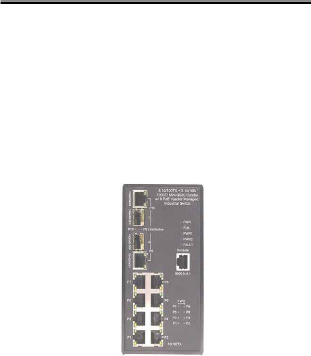
2.2 Front Panel
The Front Panel of the 8 10/100TX w/ X-Ring Managed Industrial Switch is shown as below:
Front Panel of the industrial switch
Technical Support: 1-800-260-1312 |
International: 00-1-952-941-7600 |
Transition Networks |
SISPM1040-182D-LR |
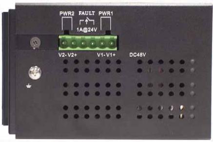
2.3 Bottom View
The bottom panel of the 8 10/100TX w/ X-Ring Managed Industrial Switch has one
terminal block connector for two (2) DC power inputs and one fault alarm.
Bottom Panel of the industrial switch
Technical Support: 1-800-260-1312 |
International: 00-1-952-941-7600 |
10
Transition Networks |
SISPM1040-182D |
2.4 LED Indicators
The diagnostic LEDs that provide real-time status information are located on the front panel of the industrial switch. The following table provides the description of the LED status and their meanings.
|
|
|
|
|
|
|
|
|
LED |
Color |
|
Status |
|
Meaning |
|
|
|
|
|
|
|
|
|
|
PWR |
Green |
|
On |
|
The switch unit is powered on |
|
|
|
|
|
|
|
||
|
|
|
|
Off |
|
No power |
|
|
|
|
|
|
|
|
|
|
|
|
|
On |
|
The industrial switch is the master of the |
|
|
|
|
|
|
X-Ring group |
|
|
|
R.M. |
Green |
|
|
|
|
|
|
|
|
|
|
|
||
|
|
|
|
Off |
|
The industrial switch is not a ring master in |
|
|
|
|
|
|
the X-Ring group |
|
|
|
|
|
|
|
|
|
|
|
|
|
|
|
|
|
|
|
PWR1 |
Green |
|
On |
|
Power 1 is active |
|
|
|
|
|
|
|
||
|
|
|
|
Off |
|
Power 1 is inactive |
|
|
|
|
|
|
|
|
|
|
PWR2 |
Green |
|
On |
|
Power 2 is active |
|
|
|
|
|
|
|
||
|
|
|
|
Off |
|
Power 2 is inactive |
|
|
|
|
|
|
|
|
|
|
FAULT |
Red |
|
On |
|
Power or port failure |
|
|
|
|
|
|
|
||
|
|
|
|
Off |
|
No failures |
|
|
|
|
|
|
|
|
|
|
|
|
|
On |
|
A network device is detected. |
|
|
|
Green |
|
|
|
|
|
|
|
|
Blinking |
|
The port is transmitting or receiving packets |
|
|
|
P9, P10 (RJ- |
(Upper LED) |
|
|
from the TX device. |
|
|
|
|
|
|
|
|
|
|
|
|
|
Off |
|
No device attached |
|
|
|
45) |
|
|
|
|
||
|
|
|
|
|
|
|
|
|
|
Green |
|
On |
|
1000M |
|
|
|
|
|
|
|
|
|
|
|
(Lower LED) |
|
|
|
|
|
|
|
|
Off |
|
10/100M |
|
|
|
|
|
|
|
|
||
|
|
|
|
|
|
|
|
|
|
|
|
|
|
|
|
Technical Support: 1-800-260-1312 |
International: 00-1-952-941-7600 |

Transition Networks SISPM1040-182D-LR
Link/Active |
|
On |
The SFP port is linking |
|
|
|
|
||
(P9, P10 |
Green |
Blinks |
The port is transmitting or receiving packets |
|
from the TX device. |
||||
SFP) |
|
|||
|
|
|||
|
|
|
||
|
|
|
|
|
|
|
Off |
No device attached |
|
|
|
|
|
|
|
|
On |
A network device is detected. |
|
|
|
|
|
|
|
Green |
Blinking |
The port is transmitting or receiving packets |
|
|
from the TX device. |
|||
|
|
|
||
|
|
|
|
|
P1 ~ P8 |
|
Off |
No device attached |
|
|
|
|
||
|
|
On |
The port is operating in full-duplex mode. |
|
|
|
|
|
|
|
Amber |
Blinking |
Collision of Packets occurs. |
|
|
|
|
||
|
|
Off |
The port is in half-duplex mode or no device |
|
|
|
is attached. |
||
|
|
|
||
|
|
|
|
|
|
|
Green |
A powered device is connected utilizing |
|
FWD (P1 ~ |
|
Power over Ethernet on the port |
||
Green |
|
|||
P8) |
|
|
||
|
Off |
No device is connected or power forwarding |
||
|
|
|||
|
|
fails |
||
|
|
|
Technical Support: 1-800-260-1312 |
International: 00-1-952-941-7600 |
|
|
12
Transition Networks |
SISPM1040-182D |
Chapter 3 Hardware Installation
This chapter describes how to physically install the 8 10/100TX w/ X-Ring Managed
Industrial Switch.
3.1Installation Steps
1.Unpack the Industrial switch
2.Check if the DIN-Rail is screwed on the Industrial switch or not. If the DIN-Rail is not screwed on the Industrial switch, please refer to DIN-Rail Mounting section for DINRail installation. If users want to wall mount the Industrial switch, please refer to Wall Mount Plate Mounting section for wall mount plate installation.
3.Hang the Industrial switch on the DIN-Rail track or wall.
4.Power on the Industrial switch. Please refer to the Wiring the Power Inputs section for information about how to wire power. The power LED on the Industrial switch will light up. Please refer to the LED Indicators section.
5.Prepare the twisted-pair, straight through Category 5 cable for Ethernet connection.
6.Insert one side of RJ-45 cable (category 5) into the Industrial switch Ethernet port (RJ-45 port) and another side of RJ-45 cable (category 5) to the network device’s Ethernet port (RJ-45 port), ex: Switch PC or Server. The UTP port (RJ-45) LED on the Industrial switch will light up when the cable is connected with the network device. Please refer to the LED Indicators section.
[NOTE] Make sure that the connected network devices support MDI/MDI-X. If it does not
support, use the crossover category-5 cable.
7.When all connections are set and LED lights all show normal, the installation is complete.
Technical Support: 1-800-260-1312 |
International: 00-1-952-941-7600 |
Transition Networks |
SISPM1040-182D-LR |
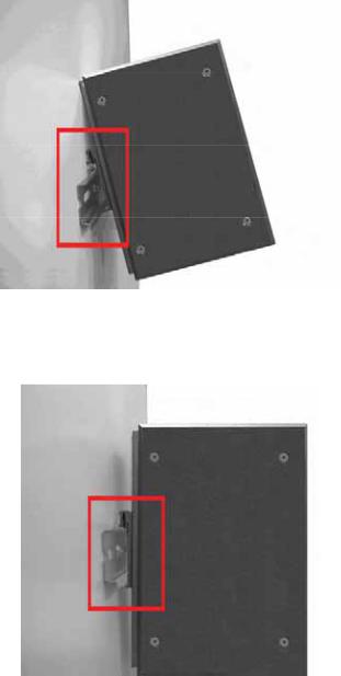
3.2 DIN-Rail Mounting
The DIN-Rail is factory installed. If the DIN-Rail is not screwed on the industrial switch, please see the following pictures. Follow the steps below to hang the industrial switch.
Technical Support: 1-800-260-1312 |
International: 00-1-952-941-7600 |
14
Transition Networks |
SISPM1040-182D |
1.First, insert the top of DIN-Rail into the track.
2.Then, lightly push the DIN-Rail into the track.
3.Verify the DIN-Rail is tightened.
4.To remove the industrial switch from the track, reverse above steps.
Technical Support: 1-800-260-1312 |
International: 00-1-952-941-7600 |
Transition Networks |
SISPM1040-182D |
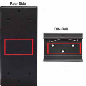
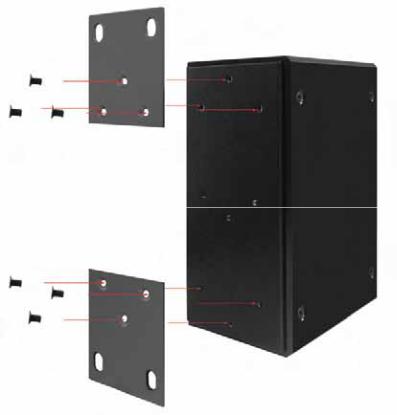
3.3 Wall Mount Plate Mounting
Follow the steps below to mount the industrial switch with wall mount plate.
1.Remove the DIN-Rail from the industrial switch; loose the screws to remove the DINRail.
2.Place the wall mount plate on the rear panel of the industrial switch.
3.Use the screws to screw the wall mount plate on the industrial switch.
4.Use the hook holes at the corners of the wall mount plate to hang the industrial switch on the wall.
5.To remove the wall mount plate, reverse the above steps.
Technical Support: 1-800-260-1312 |
International: 00-1-952-941-7600 |
Transition Networks |
SISPM1040-182D |
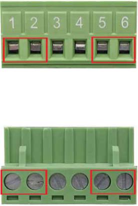
3.4 Wiring the Power Inputs
Please follow the steps below to insert the power wire.
1.Insert AC or DC power wires into the contacts 1 and 2 for power 1, or 5 and 6 for power 2.
2. Tighten the wire-clamp screws.
[NOTE] The wire gauge should be in the range 12 ~ 24 AWG.
Technical Support: 1-800-260-1312 |
International: 00-1-952-941-7600 |

Transition Networks |
SISPM1040-182D |
3.5 Wiring the Fault Alarm Contact
The fault alarm contacts are in the middle of the terminal block connector as the picture below shows. If configured the switch will detect power failure, or port link failure (available for managed model) and then form an open circuit. The following illustration shows an application example for wiring the fault alarm contacts.
Insert the wires into the fault alarm contacts
[NOTE] The wire gauge for the terminal block should be in the range between 12 ~ 24 AWG.
Technical Support: 1-800-260-1312 |
International: 00-1-952-941-7600 |

Transition Networks |
SISPM1040-182D |
3.6Cabling
Use four twisted-pair, Category 5e or above cabling for RJ-45 port connection. The cable between the switch and the link partner (switch, hub, workstation, etc.) must be less than 100 meters (328 ft.) long.
Fiber segment using single-mode connector type must use 9/125 μm single-mode fiber cable. User can connect two devices in the distance up to 30km.
Fiber segment using multi-mode connector type must use 50 or 62.5/125 μm multimode fiber cable. User can connect two devices up to 2km distances.
Gigabit Copper/SFP (mini-GBIC) combo port:
The Industrial switch has auto-detected Giga port—Gigabit Copper/SFP combo ports. The Gigabit Copper (10/100/1000T) ports should use Category 5e or above UTP/STP cable for the connection up to 1000Mbps. The small form-factor pluggable (SFP) is a compact optical transceiver used in optical communications for both telecommunication and data communications. The SFP slots supporting dual mode can switch the connection speed between 100 and 1000Mbps. They are used for connecting to the network segment with single or multi-mode fiber. Choose the appropriate SFP transceiver to plug into the slots. Then use proper multi-mode or single-mode fiber according to the transceiver. Fiber optic signals transmit at speeds up to 1000 Mbps and are immune to electrical interference.
Note The SFP/Copper Combo port can’t both work at the same time. The SFP port has higher priority than the copper port; if you insert the 1000M SFP transceiver (connected to the remote device via fiber cable) into the SFP port, the connection of the accompanying copper port link will down.
If you insert the 100M SFP transceiver into the SFP port even without a fiber connection to the remote, the connection of the accompanying copper port will link down immediately.
Technical Support: 1-800-260-1312 |
International: 00-1-952-941-7600 |
Transition Networks |
SISPM1040-182D-LR |
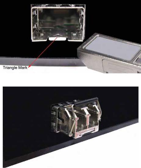
To connect the transceiver and LC cable, please follow the steps shown below:
First, insert the transceiver into the SFP module. Notice that the triangle mark is the bottom of the module.
Transceiver to the SFP module
Transceiver Inserted
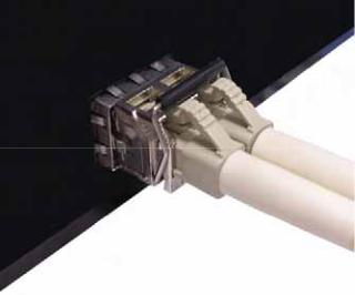
Second, insert the fiber cable of LC connector into the transceiver.
Technical Support: 1-800-260-1312 |
International: 00-1-952-941-7600 |
20
Transition Networks |
SISPM1040-182D-LR |
LC connector to the transceiver
Technical Support: 1-800-260-1312 |
International: 00-1-952-941-7600 |
21
Transition Networks |
SISPM1040-182D-LR |
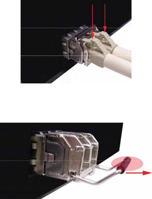
To remove the LC connector from the transceiver, please follow the steps shown below:
First, press the upper side of the LC connector to release from the transceiver and pull it out.
Remove LC connector
Second, push down the metal loop and pull the transceiver out by the plastic handle.
Pull out from the transceiver
Technical Support: 1-800-260-1312 |
International: 00-1-952-941-7600 |
22
 Loading...