


Tracer
Table of contents
 Loading...
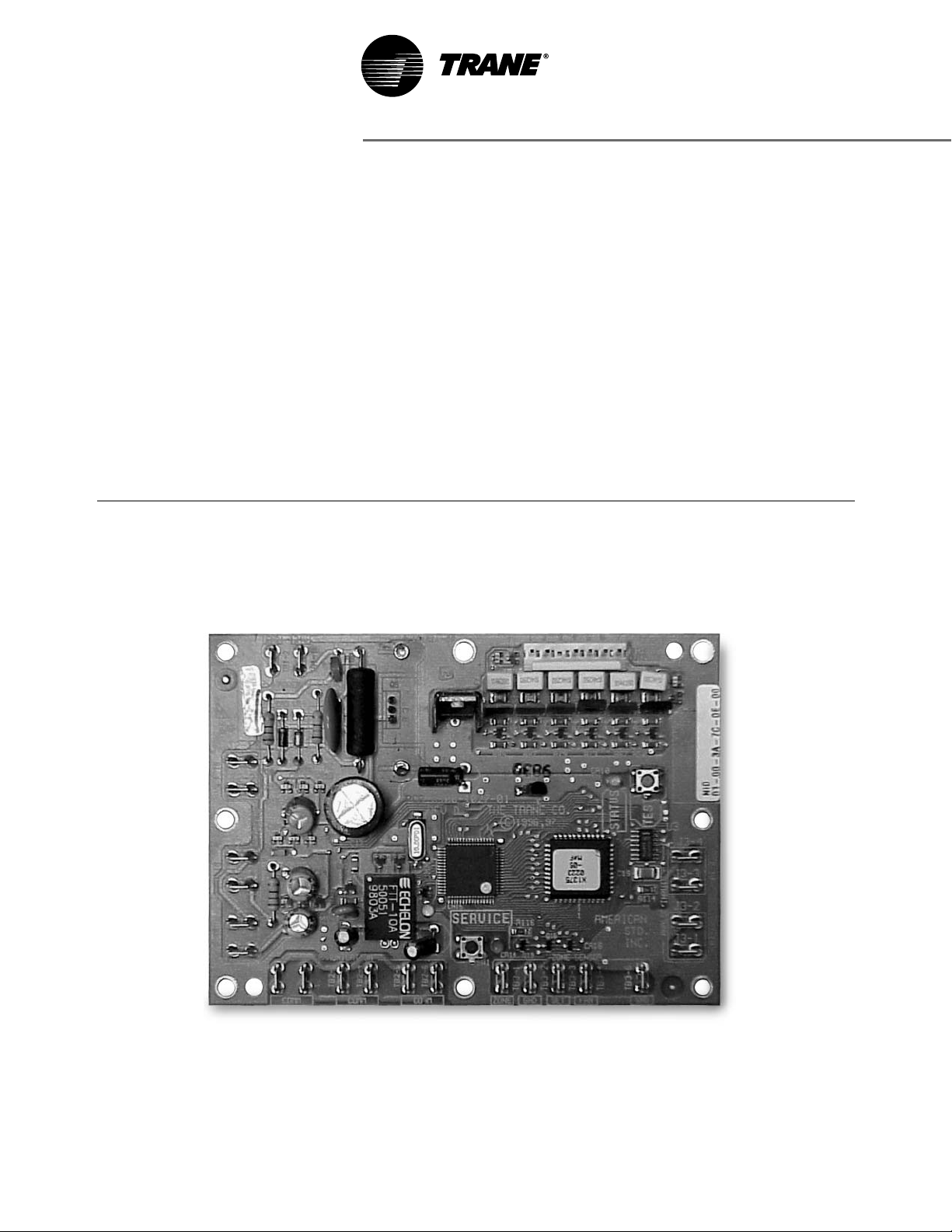
WSHP-IOP-2
May 1998
Installation, Operation,
and Programming
Tracer™ ZN510 Controller

Literature
History
© 1998, American Standard Company
Installation, Operation,
and Programming
WSHP-IOP-2
Library Service Literature
Product Section Unitary
Product Water-Source Heat Pumps
Model 000
Literature Type
Installation, Operation,
and Programming
Sequence 1
Date April 1998
File No. SL-UN-000-WSHP-IOP-2-0498
Supersedes New
Related Literature
z CNT-IOP-1 ZN510 1 Controller:
Installation, Operation, and Pro-
graming
z WSHP-PD-1 Water-Source Heat
Pump Controller Product Data
Sheet
z WMCA-PD-1 ZN510 Loop Con-
troller Product Data sheet
z WSHP-IOP-3 ZN510 Water-
Source Heat Pump Controller
Installation, Operation, and Pro-
gramming Guide
z WMCA-IOP-1 ZN510 Controller
Installation, Operation, and Pro-
gramming Guide
The Trane Company has a policy of continuous product improvement and it reserves the right to change
specifications and design without notice.

Table of Contents
Start-up Procedure 4
Power-up Sequence 5
Unit Identification Tag 6
Unit Operation 7
General Information 7
Communication 7
Power 8
Binary Outputs 8
Analog Outputs 9
Binary Inputs 9
Analog Inputs 12
Zone Sensors 15
Heating or Cooling Control
Mode Operation
18
Single or Dual Compressor
Operation
19
Data Sharing 20
Configuration 21
Troubleshooting 22
Diagnostics 27
ZN510 Controller Replacement 28
Wiring Diagram 29
Hardware Specifications 31
Appendix 33

4
Start-up
Procedure
Installation of New Units
1. Follow all instruction for
installation of water source
heat pumps as detailed in the
IOM (Installation Operation
Maintenance manual).
2. Disconnect power or disable
the circuit breaker to unit.
3. Run communication link wire to
field terminal strips 14 and 16.
(See wiring diagram in the
unit).
4. Install zone sensor to low
voltage control terminals 1
through 6. (See wiring diagram
in the unit and zone sensor
submittals).
5. Verify that water connections
have been made to unit, then
ensure that water is circulating
through the unit.
6. Reapply power.
7. Check for STATUS GREEN LED
operation to ensure power and
communication has been made
to the ZN510
™
.
Peel IDENTIFICATION TAG from unit
and place in the ZN510 IOP, on a
copy of Sheet 6 of this document, or
on building plans for future location
use. The actual room location on the
tag may be hand written.
Zone Sensor Placement
Zone sensor location is an important
element of effective room control
and comfort.
The best sensor location is typically
on a wall, remote from the
HVAC unit.
Readings at this location assure that
the desired setpoint is achieved
across the space, not just near the
unit itself. It may be necessary to
subdivide the zone with multiple
units to ensure adequate control
and comfort.
The following are typical areas
where the zone sensor should not
be mounted:
z Near drafts or “dead spots”
(e.g., behind doors or corners)
z Near hot or cold air ducts
z Near radiant heat (e.g., heat
emitted from appliances or the
sun)
z Near concealed pipes or
chimneys
z On outside walls or other non-
conditioned surfaces
z In air flows from adjacent zones
or other units

5
Power Up
Sequence
Power Up Sequence
When 24 VAC power initially is
applied to the ZN510 controller, the
following sequence occurs:
1. All outputs are controlled off.
2. The controller reads all inputs
to determine their initial values.
Note: Because the space tempera-
ture can be hardwired to the con-
troller or communicated, the
controller waits for several minutes
to check for the presence of a com-
municated value.
3. A random start time is hard
coded on every board and
cannot be disabled. The board
generates a random time delay
between 0 and 25 seconds.
Once this time expires, the
power up control wait time (if
configured) will wait for 120
seconds. The power up control
wait allows ample time for a
communicated request to
arrive. If the power up control
wait time expires, and the
controller does not receive a
communicated occupancy
command, the unit assumes
stand alone operation.
4. Normal operation begins.
6
Unit
Identification
Tag
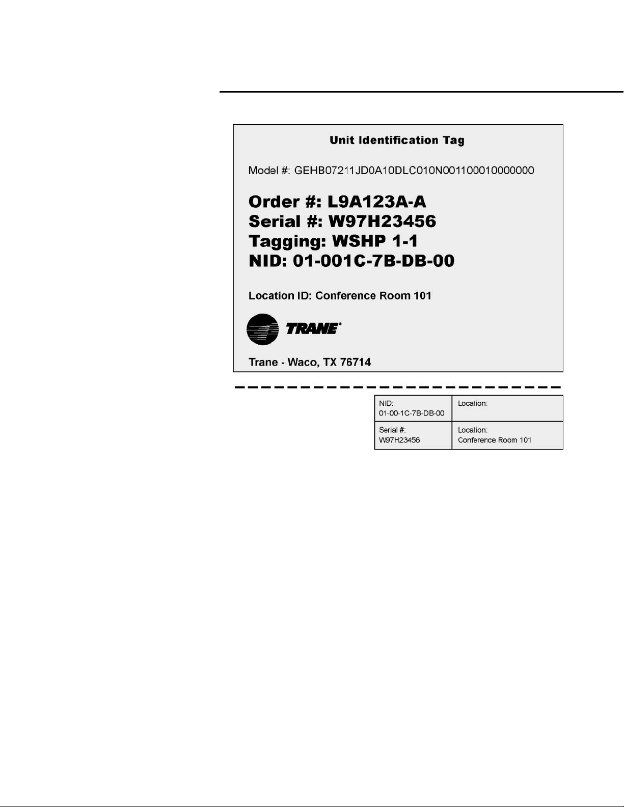
Unit Identification Tag
The unit identification tag is factory
mounted and provided for easy
identification of an installed unit. It
contains model number, tagging,
and location information. See
Figure 1.
The top portion of the unit
identification tag remains
permanently affixed to the unit for
identity purposes. The bottom
portion of the tag provides pertinent
information that is removable to be
placed on building plans or in the
ZN510 IOP on page 33. This provides
identification history about the unit’s
location for quick reference.
These tags provide information
about unit location, unit serial
number, and NID (neuron
identification number). The NID is
similar to the serial number of the
unit but is specific to the
identification of the ZN510 Board.
The location identification is a
customer defined, clear English
description, of the unit’s physical
location. This is a 27 character
description of the location. For
example, if the location identification
for a unit is “Conference Room 101”,
the ZN510 and Rover (the Trane
Comm 5 service tool) will recognize
this clear English description so
maintenance can be performed on
the appropriate unit. If location
identification is not defined, it will
default to the unit serial number. This
provides some information so the
user has multiple references to the
unit. The blank location is provided
for field modification in case the unit
is moved from the initial location.
Figure 1: Unit Identification Tag
Note: Fold and tear carefully along dashed
removable line.
7
General Information
The ZN510 controller is a
microprocessor-based direct digital
controller that controls a variety of
water source heat pump equipment
including:
z Standard efficiency horizontal
and vertical units up to 10 tons.
z High efficiency horizontal and
vertical units.
z Console water source heat
pumps.
ZN510 is designed to provide
accurate and reliable zone
temperature control by using
custom proportional integral (PI)
algorithms. The controller is factory
installed and configured to support:
z Single fan speed.
z Up to two compressors.
z Reversing valve.
z 2-position outdoor air damper
or generic binary output.
Peer-to-peer communication across
controllers is possible even when a
building automation system is not
present. ZN510 is also adaptable as
a standalone system.
Communication
The ZN510 controller communicates
via Trane’s Comm5 protocol.
Typically, a communication link is
applied between unit controllers and
a building automation system.
Communication is also possible
with Trane’s service tool Rover
™
.
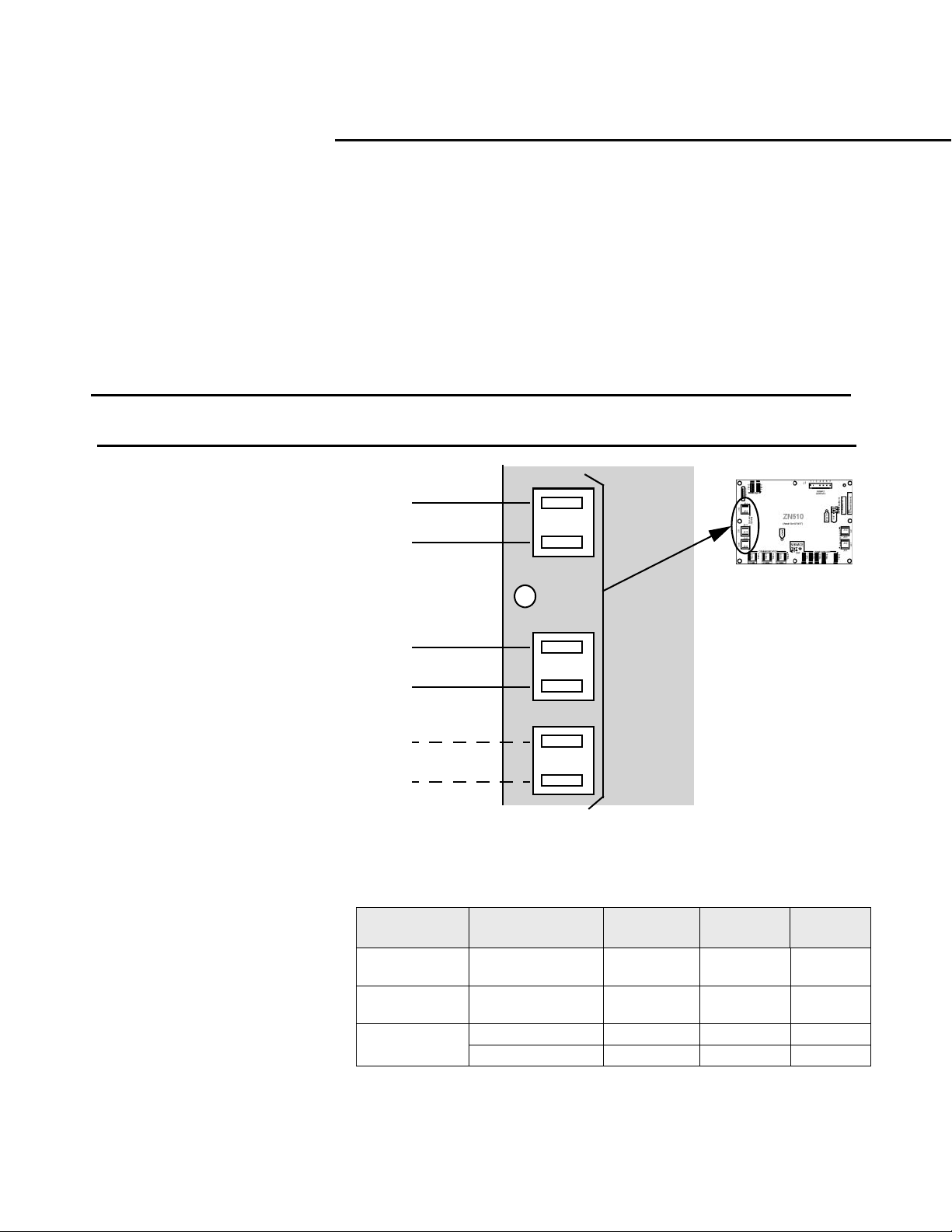
ZN510 provides a total of six 1/4-inch
quick-connect terminals for
connection to the Comm5
communication link. These
connections include:
z Two terminals (TB2-1, TB2-2)
are provided for direct con-
nection of Rover to the ZN510
Board or provided as spare ter-
minals.
z Two terminals (TB2-3, TB2-4)
are connected to the field
terminal strip (1TB1-14,
1TB1-16) for connection to the
communication link (daisy
chain).
z Two terminals (TB2-5, TB2-6)
are connected to the field
terminal strip (1TB1-5, 1TB1-6)
which should be connected to
the zone sensor communication
jack. This provides direct
connect of Rover to the commu-
nication link without having to
connect directly to the ZN510
board or provided as spare ter-
minals.
z The field terminal strip 1TB1
provides screw terminations for
all field connections.
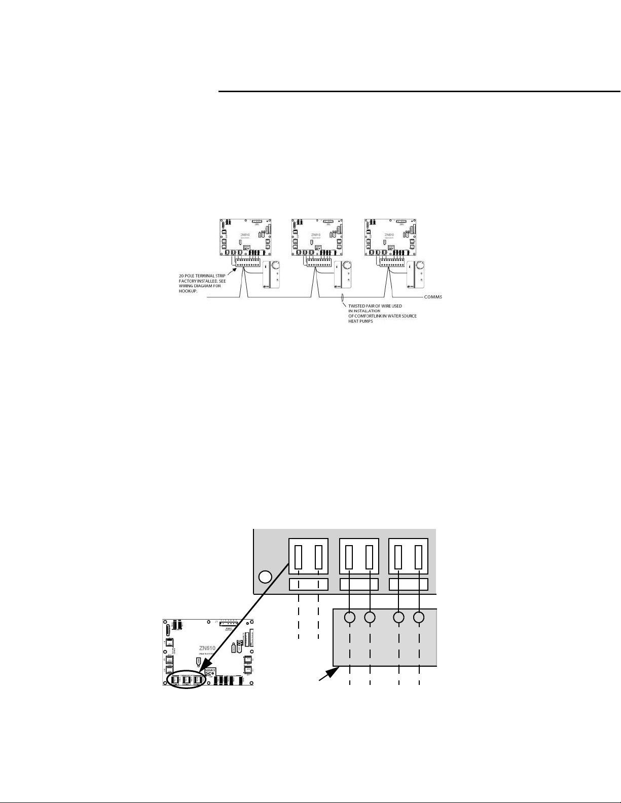
Figure 2: Communication connections
COMM COMM COMM
TB2-1
TB2-2
TB2-3
TB2-4
TB2-5
TB2-6
Zone
Sensor
Communication
Link
Space
Communication
Connection
1TB1-14
1TB1-16
1TB1-5
1TB1-6
20 pole low voltage
terminal strip screw
connections for
field hook-up
Figure 3: Communication Wiring
Unit Operation

8
Power
The ZN510 controller is powered by 24
VAC. A total of two 1/4-inch quick-
connect terminals are provided for 24
VAC connection to the board. See
Figure 4 for ZN510 power requirement.
Note: Power for field installed ancil-
lary devices is not available from the
board. It must be tapped at trans-
former. See Table 21 for excess power
available.
Factory Supplied Transformer
24VAC
Line
Vol tage
Figure 4: Power Connections
Binary Outputs
The ZN510 uses five of its binary
outputs to control heat pump units.
Outputs are load side switching triacs.
The triac acts as a switch by either
making or breaking the circuit
between the load (reversing valve,
damper, contactor, relay) and ground.
See Figure 5 for the configuration of
the five binary outputs.
2-Position Damper Actuator or
Generic Binary Output
Binary output 6 (BOP 6) is factory
configured to control a normally
closed 2-position outdoor air damper.
It may be field modified to control a
generic output for control by a
building automation system. If set up
as a generic output, the controller
does not use BOP 6 as part of the
normal control. A building automation
system must issue commands to
control the generic binary output.
Note:
z During occupied mode, the
outdoor air damper is closed
when the fan is controlled off.
z During unoccupied mode, the
outdoor air damper normally
remains closed.
z 2-position damper must not
exceed 10 VA power output from
board.
J1-1
Binary Outputs
Figure 5: Binary outputs
.
Table 1: BOP 6 control of a 2-position outdoor air damper
Model Fan Operation Outdoor Air Damper
Occupied
On or cycling
Off
Open
Closed
Occupied warm up or
cool down
On or cycling Closed
Occupied standby On or cycling Closed
Unoccupied Cycling Closed
Diagnostic present Diagnostic dependent Closed
BOP 1 (Fan)
BOP 2 (Reversing Valve)
BOP 3 (Not available)
BOP 5 (Compressor 1)
BOP 6 (Compressor 2)
BOP 7
J1-2
J1-3
J1-4
J1-5
J1-6
J1-7
24VAC
Unit Operation
1TB1-17
1TB1-18
Field installed
2 position
damper actuator
BOP 4 (Not Used)
9
Unit Operation
Analog Outputs
ZN510 does not use analog outputs.
Binary Inputs
The ZN510 controller has three
available binary inputs (BI). These
inputs are factory-configured for
the following functions:
z BI 1= Low temperature
detection (freezestat) (Circuit 2).
z BI 2 = Condensate overflow.
z BI 3 = Occupancy or generic
binary input.
Each binary input may be
configured as not used depending
on options selected. BI 3 is
configured as a normally open
occupancy input, but may be field
modified for generic binary input
which is only supported by a build-
ing automation system.
Note:
The diagnostic functions related to
binary inputs such as low tempera-
ture detection and condensate
overflow are fixed sequences.
Each binary input associates an
input signal of 0 VAC with open
contacts and 24 VAC with closed
contacts. See Figure 6 for typical
binary input configurations for the
heat pump.
Figure 6: Binary inputs.
BI 1
J2-1
J2-2
J2-3
J2-4
J2-5
J2-6
Field Wired
Occupancy Input
BI 2BI 3
Binary Inputs
Condensate Overflow
Low Temperature
Detection (Circuit 2)
Table 2: Binary input configurations
Binary Input Description
Configuratio
n
Contact
Closure
Contact
Open
BI 1
Low Temperature
Detection (Cir 2)
Normally
closed
Normal Diagnostic
BI 2 Condensate Overflow
Normally
closed
Normal Diagnostic
BI 3
Occupancy Normally open Unoccupied Occupied
Generic Normally open Normal Normal
Note:
See Page 10 for specific information concerning BI 1, BI 2 and BI 3.
Output Overrides
The ZN510 controller includes a
manual output test function. Use this
feature to manually exercise the
outputs in a defined sequence. The
purpose of the test sequence, is to
verify output and end device
operation. Use the manual output
test to:
z Verify output wiring and
operation without using Trane’s
service tool, Rover.
z Force compressor operation,
allowing the technician to use
refrigerant gauges or other test
equipment to verify unit
operation.
The test sequence resets unit
diagnostics and attempts to restore
normal unit operation prior to
testing the outputs. If the diagnostics
remains after a reset, the status LED
indicates the diagnostic condition is
still present and has affected the
manual output test. See
Troubleshooting section for Green
LED and Testing Heat Pump
Configurations on page 21 & 22.

10
Unit Operation
Low Temperature Detection
The low temperature detection
diagnostic protects the heat
exchanger by using an analog
leaving water temperature sensor to
protect refrigerant circuit 1 and a
binary low temperature detection
device to protect refrigerant circuit
2. Each individual refrigerant circuit
is disabled when the low
temperature condition exists for that
circuit.
For two compressor units, the
controller responds to low
temperature detection by allowing
the fan to operate, while disabling
the compressor for the faulty circuit.
The compressor for the normal
circuit continues to operate. The
outdoor air damper also operates
normally.
All unit operation is disabled when
the heat pump shuts down both
circuits, due to low temperature
conditions. See Table 3 for more
information.
Table 3: ZN510 response to low temperature detection diagnostic
Description
Fan
Operation
Compressor Operation
Damper
Operation
Low Temperature Detection
(Circuit 1)
Enabled
Circuit 1-Disabled
Circuit 2-Normal Operation
Normal
operation
Low Temperature Detection
(Circuit 2)
Enabled
Circuit 1-Normal Operation
Circuit 2-Disabled
Normal
operation
Low Temperature Detection
(Circuits 1 and 2)
Disabled
Circuit 1-Disabled
Circuit 2-Disabled
Closed
Note:
z The low temperature detection device automatically resets when the heat exchanger temperature returns to
normal. However, you must manually reset the low temperature detection diagnostic to clear the diagnostic and
restart the unit. Refer to page 28 on how to reset a unit.
z If BOP 6 is configured as a generic binary output, the state of the output is not affected by the low temperature
detection diagnostic or by other diagnostics.
Condensate Overflow
A condensate overflow switch
detects the condensate condition.
The condensate overflow switch is a
normally closed device. This switch
is physically connected to the binary
input 2 (BI 2). When the
condensation reaches the trip point,
the binary input detects the
diagnostic condition. A condensate
overflow signal generates a
diagnostic which disables the fan,
disables all compressors, and closes
the 2-position outdoor air damper
(when present). The condensate
overflow diagnostic does not affect
the generic binary output (when
present).
Note:
The condensate overflow switch,
located in the condensate pan, auto-
matically resets when the conden-
sation returns to normal levels.
However, you must manually reset
the controller’s condensate over-
flow diagnostic to clear the diagnos-
tic and restart the unit. Refer to page
28 on how to reset a unit.
Occupancy
ZN510 uses the occupancy binary
input for two occupancy-related
functions. For standalone
controllers (any unit not receiving a
communicated occupancy request,
typically from a building automation
system), the occupancy binary input
determines the unit’s occupancy
based on the hardwired signal.
Typically, the signal is a dry set of
binary contacts which is either
connected to a switch or timeclock
contacts.
When a hardwired occupancy signal
is open, the unit switches to
occupied mode (if the occupancy
input is configured as normally
open). When a hardwired
occupancy signal is closed, the
controller switches to Unoccupied
mode.
Loading...