


 Loading...
Diagnostic
Troubleshooting
Repair
Series R®
70-125 Ton Air-Cooled and Water-Cooled
Rotary Liquid Chillers
Model
RTAA 70-125 Ton
RTWA 70-125 Ton
RTUA 70-125 Ton
|
|
August 2005 |
RLC-SVD03A-EN |
© American Standard Inc. 2005

NOTICE: Warnings and Cautions appear at appropriate sections throughout this literature. Read these carefully.
WARNING: Indicates a potentially hazardous situation which, if not avoided, could result in death or serious injury.
CAUTION: Indicates a potentially hazardous situation which, if not avoided, may result in minor or moderate injury. It may also be used to alert against unsafe practices.
CAUTION: Indicates a situation that may result in equipment or propertydamage only accidents.
Important - Read This First!
This manual is intended for experienced service personnel familiar with the proper use of electrical diagnostic instruments and all personal safety procedures when working on live electrical circuits.
This Manual is not intended for individuals who have not been properly trained in handling live electrical circuits.
Environmental Concerns!
Scientific research has shown that certain man-made chemicals can affect the earth’s naturally occurring stratospheric ozone layer when released to the atmosphere. In particular, several of the identified chemicals that may affect the ozone layer are refrigerants that contain Chlorine, Fluorine and Carbon (CFCs) and those containing Hydrogen, Chlorine, Fluorine and Carbon (HCFCs). Not all refrigerants containing these compounds have the same potential impact to the environment. Trane advocates the responsible handling of all refrigerants— including industry replacements for CFCs such as and HCFCs and HFCs.
Responsible Refrigerant Practices!
Trane believes that responsible refrigerant practices are important to the environment, our customers, and the air conditioning industry. All technicians who handle refrigerants must be certified. The Federal Clean Air Act (Section 608) sets forth the requirements for handling, reclaiming, recovering and recycling of certain refrigerants and the equipment that is used in these service procedures. In addition, some states or municipalities may have additional requirements that must also be adhered to for responsible management of refrigerants. Know the applicable laws and follow them.
WARNING
Contains Refrigerant!
System contains oil and refrigerant under high pressure. Recover refrigerant to relieve pressure before opening the system. See unit nameplate for refrigerant type. Do not use non-approved refrigerants, refrigerant substitutes, or refrigerant additives.
Failure to follow proper procedures or the use of non-approved refrigerants, refrigerant substitutes, or refrigerant additives could result in death or serious injury or equipment damage.
2 |
RLC-SVD03A-EN |

Contents
General Information . . . . . . . . . . . . . . . . . . . . . . . . . . . . . . . . . . . . . . . . . . 4
Service Philosophy . . . . . . . . . . . . . . . . . . . . . . . . . . . . . . . . . . . . . . . . . . . . . . 4
System Description . . . . . . . . . . . . . . . . . . . . . . . . . . . . . . . . . . . . . . . . . . . . . . 5
System Level Components . . . . . . . . . . . . . . . . . . . . . . . . . . . . . . . . . . . . . . . . 5
Interprocessor Communications . . . . . . . . . . . . . . . . . . . . . . . . . . . . . . . . 8
IPC Diagnostics . . . . . . . . . . . . . . . . . . . . . . . . . . . . . . . . . . . . . . . . . . . . . . . . . 8
Troubleshooting Modules Using IPC Diagnostics . . . . . . . . . . . . . . . . . . . . . . . 9
Troubleshooting Procedure . . . . . . . . . . . . . . . . . . . . . . . . . . . . . . . . . . . . . . . 12
Temperature Sensor Checkout . . . . . . . . . . . . . . . . . . . . . . . . . . . . . . . . 15
Temperature Sensor Checkout Procedure . . . . . . . . . . . . . . . . . . . . . . . . . . . 15
Compressor Operation . . . . . . . . . . . . . . . . . . . . . . . . . . . . . . . . . . . . . . . 19
Restart Inhibit Timer . . . . . . . . . . . . . . . . . . . . . . . . . . . . . . . . . . . . . . . . . . . . 19
Compressor Start/Stop . . . . . . . . . . . . . . . . . . . . . . . . . . . . . . . . . . . . . . 20
Variable Speed Inverter/Condenser Fan Control . . . . . . . . . . . . . . . . . . 21
Outdoor Air Temperature and Fan Control . . . . . . . . . . . . . . . . . . . . . . . . . . . 22
VSF Inverter Fault . . . . . . . . . . . . . . . . . . . . . . . . . . . . . . . . . . . . . . . . . . . . . . 22
Current Transformer . . . . . . . . . . . . . . . . . . . . . . . . . . . . . . . . . . . . . . . . . 23
CT and MCSP Compressor Current Input Checkout Procedure . . . . . . . . . . . 24
Under-Over Voltage Transformer . . . . . . . . . . . . . . . . . . . . . . . . . . . . . . 32
Under-Over Voltage Transformer Checkout . . . . . . . . . . . . . . . . . . . . . . . . . . 32
Compressor Capacity . . . . . . . . . . . . . . . . . . . . . . . . . . . . . . . . . . . . . . . . 34
Checkout Procedure for MCSP Load/Unload Outputs . . . . . . . . . . . . . . . . . . 35 Checkout Procedure for the Slide Valve and Load/
Unload Solenoids . . . . . . . . . . . . . . . . . . . . . . . . . . . . . . . . . . . . . . . . . . . . . . . 36 Checkout Procedure for MCSP Step Load Output . . . . . . . . . . . . . . . . . . . . . 39 Checkout Procedure for Step Load Solenoid Valve
and Piston . . . . . . . . . . . . . . . . . . . . . . . . . . . . . . . . . . . . . . . . . . . . . . . . . . . . 40
Module Power and Miscellaneous I/O . . . . . . . . . . . . . . . . . . . . . . . . . . 41
Power Supply . . . . . . . . . . . . . . . . . . . . . . . . . . . . . . . . . . . . . . . . . . . . . . . . . 41 Clear Language Display (CLD) 1U6 Keypad Overview . . . . . . . . . . . . . . . . . . 42 Chiller Module (CPM) (1U1) . . . . . . . . . . . . . . . . . . . . . . . . . . . . . . . . . . . . . . . 46 Options Module (CSR) (1U2) . . . . . . . . . . . . . . . . . . . . . . . . . . . . . . . . . . . . . . 50 Electronic Expansion Valve Module (EXV) (1U3) . . . . . . . . . . . . . . . . . . . . . . . 58 Compressor Module (MCSP) (1U4 AND 1U5) . . . . . . . . . . . . . . . . . . . . . . . . . 72 Interprocessor Communication Bridge Module (IPCB) (1U7) . . . . . . . . . . . . . 78 LonTalk® Communications Interface - Chillers Module
(LCI-C) (1U8) . . . . . . . . . . . . . . . . . . . . . . . . . . . . . . . . . . . . . . . . . . . . . . . . . . 79
Variable Speed Fan System . . . . . . . . . . . . . . . . . . . . . . . . . . . . . . . . . . . 80
Inverter Diagnostics . . . . . . . . . . . . . . . . . . . . . . . . . . . . . . . . . . . . . . . . . . . . 80
Troubleshooting Procedure . . . . . . . . . . . . . . . . . . . . . . . . . . . . . . . . . . . . . . . 82
Other Service Features . . . . . . . . . . . . . . . . . . . . . . . . . . . . . . . . . . . . . . . 85
Service Pumpdown . . . . . . . . . . . . . . . . . . . . . . . . . . . . . . . . . . . . . . . . . . . . . 85
Circuit Lockout . . . . . . . . . . . . . . . . . . . . . . . . . . . . . . . . . . . . . . . . . . . . . . . . 87
Circuit Diagnostic Reset . . . . . . . . . . . . . . . . . . . . . . . . . . . . . . . . . . . . . . . . . 87
RLC-SVD03A-EN |
3 |

General Information
The Unit Control Modules (UCMs) described in this troubleshooting guide provide a microprocessor based refrigeration control system, intended for use with Trane 70-125 ton helical rotor chillers. Six types of modules are used, and throughout this publication will be referred to by their abbreviations or their Line Wiring Drawing Designations, see Table 1.
Table 1 |
Unit Control Module Designations |
||
|
|
|
|
Line Drawing |
Controller Name |
Abbrev. |
|
Designation |
Chiller Module |
CPM |
|
|
|
|
|
1U2 |
|
Options Module |
CSR |
|
|
|
|
1U3 |
|
Expansion Valve Module |
EXV |
|
|
|
|
1U4 & 1U5 |
|
Compressor Module |
MCSP A & B |
|
|
|
|
1U6 |
|
Clear Language Display |
CLD |
|
|
|
|
1U7 |
|
Interprocessor |
IPCB |
|
|
Communications Bridge |
|
|
|
(Remote Display Buffer) |
|
|
|
|
|
Service Philosophy
With the exception of the fuses, no other parts on or within the modules are serviceable. The intent of the troubleshooting is to determine which module is potentially at fault and then to confirm a module problem. This is done either through voltage or resistance measurements at the suspected input or output terminals or by checking related wiring and external control devices (connectors, sensors, transformers, contactors etc.) in a process of elimination. Once a problem has been traced to a module, the module can be easily replaced using only basic tools. In general, all dip switch settings of the replaced modules should be copied onto the replacement module's dip switches before applying control power. CPM replacement is more involved as there are numerous configuration and set-up items that must be programmed at the Clear Language Display in order to insure proper unit operation.
It is helpful to include with the return of a module, a brief explanation of the problem, sales office, job name, and a contact person for possible follow-up. The note can be slipped into the module enclosure. Early and timely processing of Field Returns allows for real measurements of our product quality and reliability, providing valuable information for product improvement and possible design changes.
4 |
RLC-SVD03A-EN |

General Information
System Description
The CPM is the master module and coordinates operation of the entire system. One is used per chiller. The MCSP is a compressor protection module with one being used for each of the compressors in the chiller. The EXV is the expansion valve controller module which controls two Electronic Expansion Valves. There is one valve on each of the two refrigeration circuits.
The CLD is a two line, 40 character alphanumeric interface to the system. It allows the operator to read operating and diagnostic information, as well as change control parameters. The Interprocessor Communications Bridge (IPCB) provides an extension of the IPC link to the Remote Clear Language Display, while protecting the integrity of the IPC communications link between the local modules.
The CSR is an optional communications module which allows for communications between the chiller and a remote building automation system (i.e. Tracer, Tracer Summit, Generic BAS).
All modules in the system communicate with each other over a serial interprocessor communications bus (IPC) consisting of a twisted wire pair “daisy chain” link and RS485 type signal levels and drive capability. Multiple modules of the same type (i.e. MCSPs) in an operating system are differentiated by address dip switches.
All the modules operate from 115VAC, 50 or 60Hz power and each have their own internal step-down transformer and power supply. Each is individually fused with a replaceable fuse. The modules also are designed to segregate their high and low voltage terminals by placing the high voltage on the right side of the module and the low voltage on the left. When stacked, segregation is maintained.
In addition to the modules, there are a number of “system level” components that are closely associated with the modules. These components were specifically designed and/or characterized for operation with the modules. For this reason, the exact Trane part must be used in replacement.
System Level Components
Description
The following is a list of all the components that may be found connected to the various modules.
Transformer, Under/Over voltage
Current Transformer - Compressor
Evap EntlLvg Water Temp Sensor Pair
Sat Evap/Cprsr Suc Rfgt Temp. Sensor Pair
Sat Cond RfgtIOil Temp Sensor Pair
Outdoor Air Temperature Sensor
Zone Temp Sensor
Connector (UCM mating connectors)
Connector Keying Plug
Electronic Expansion Valve
RLC-SVD03A-EN |
5 |

General Information
High Pressure Cutout Switch
Low Pressure Cutout Switch
Variable Speed Fan Drive
Motor Temperature Thermostats
Slide Valve Load/Unload Solenoids
Step Load Solenoid Valve
Chiller Module (CPM) IU1
The CPM module performs machine (chiller) level control and protection functions. Only one CPM is present in the chiller control system. The CPM acts as the master controller to the other modules, running top level machine control algorithms, initiating and controlling all inter-module communication over the IPC, and providing parameters and operational requests (i.e. loading and unloading, starting and stopping) to the other modules in the system via the IPC. The CPM also contains nonvolatile memory, which allows it to remember configuration and set-up values, setpoints, historical diagnostics etc. for an indefinite period of time following a power loss. Direct hard wired I/O associated with the CPM includes low voltage analog inputs, low voltage binary inputs, 115 VAC binary inputs and 115 VAC (rated) relay outputs. See Chiller Module (CPM) (1U1) on page 46 for further details.
Compressor Module (MCSP) 1U4 and 1U5
The MCSP module employs the input and output circuits associated with a particular compressor and refrigeration circuit. Two MCSP modules are used in the UCM system, one for each compressor. Included are low voltage analog and digital circuits, 115 VAC input, and 115 VAC output switching devices. The output switching devices associated with the compressor motor controlling function are contained in this module. The outputs of this module control one compressor motor stop/start contactor, one compressor motor transition contactor, one oil heater, three solenoid valves (compressor load, compressor unload, step loader), and up to four fan motor contactors or groups of contactors. Refer to the chiller's line wiring diagrams for details. Dip switches are provided for redundant programming of the compressor current overload gains, and for unique IPC address identification during operation. Inputs to this module include motor temperature thermostats, thermisters, and safety switches. See Compressor Module (MCSP) (1U4 AND 1U5) on page 72 for details.
Expansion Valve Module (EXV) 1U3
The EXV module provides power and control to the stepper motor driving the electronic expansion valves of the chiller. Each module handles two valves, one in each refrigeration circuit.
Input to the EXV Module is provided by four temperature sensors (two per refrigeration circuit). The sensors are located in the respective refrigeration circuits of the chiller and sense Saturated Evaporator and Suction temperatures and calculate the superheat temperatures. High level operational commands as well as superheat setpoints are received by the EXV Module over the IPC from the CPM module to modulate the EXV's.
6 |
RLC-SVD03A-EN |

General Information
Real time data for temperatures, diagnostics and control algorithms etc. are made available to the CPM and the other modules for display and for input to higher level functions. See Electronic Expansion Valve Module (EXV) (1U3) on page 58 for details.
Options Module (CSR) 1U2
The CSR module is an optional part of the system and employs communications circuits for interface to Trane Building Automation Systems, done through 1C17. The CSR also provides inputs for hard wired external setpoints and reset functions. Included are low voltage analog and digital input circuits. See Options Module (CSR) (1U2) on page 50 for details.
Clear Language Display (CLD) 1U6
The CLD Module provides an operator interface to the system, through a two line, 40 character alphanumeric display. Three reports may be displayed and various operating parameters may be adjusted by depressing a minimal number of keys on the CLD. Also, chiller Start/Stop functions may be performed at this keypad. See Clear Language Display (CLD) 1U6 Keypad Overview on page 42 for details.
Interprocessor Communication Bridge (IPCB) 1U7
The IPCB module allows connection of a Remote Clear Language Display module to the UCM, for distances of up to 1500 feet. The Remote Clear Language Display communicates with the UCM, utilizing the same IPC protocol, and provides most of the same functions as the local CLD. The IPCB then serves to protect the UCM's IPC if wires to the Remote CLD become shorted or broken. See Section 2 and on page 75 for details.
RLC-SVD03A-EN |
7 |

Interprocessor Communications
The respective modules communicate with each other via an InterProcessor Communication link (IPC). The IPC allows the modules to work in a coordinated manner with the CPM directing overall chiller operation while each module handles specific subfunctions. This IPC link is integral and necessary to the operation of the Unit Controls and should not be confused with the Optional ICS (Integrated Comfort System) communication.
In the IPC communication protocol scheme, the CPM acts as the initiator and the arbitrator of all module communication. The CPM essentially requests all the possible “packets” of information from each module in turn, (including itself), in a predefined serial sequence. The other modules act as “responders” only and cannot initiate communication. Modules which are not currently responding to a specific request, can listen to the data and thus, indirectly, they communicate with each other. It is helpful to remember when troubleshooting that a module must be able to hear a request for its information from the CPM, or it will not talk.
The link is non-isolated, which means that a good common ground between all the modules is necessary for trouble-free operation (provided by the module enclosures' mounting using star washers). Also, the link requires consistent polarity on all of the module interconnections. Connections between modules are made at the factory, using unshielded #18 gauge twisted pair cable terminated into a 4-position MTA type connector (orange color code). This connector is plugged onto the 4 pin IPC connection jack designated as J1, located in the upper left corner of the PC board edge on all of the modules. The 4 pins actually represent 2 pairs of communications terminals (J1-1 (+) internally connected to J1-3, and J1-2 (-) internally connected to J1-4) to allow for easy daisy chaining of the bus.
IPC Diagnostics
The modules, in order to work together to control the chiller, must constantly receive information from each other over the IPC. Failure of certain modules to communicate or degradation of the communication link, could potentially result in chiller misoperation. To prevent this situation, each module monitors how often it is receiving information from designated other modules. If a module fails to receive certain other module's transmitted data over a 15 second time period it will:
1.On its own, take specific action to safely shut-down (or to default) its controlled loads.
2.Report a diagnostic to the CPM (over the IPC link).
The CPM (if it properly receives such) will then report and display the diagnostic on the Clear Language Display accordingly. The diagnostic will:
•identify which module is reporting the communication problem and
•identify which module was to have sent the missing information.
The CPM itself will then send out further commands to the other modules to shutdown or take default actions as the particular case may warrant.
All IPC diagnostics are displayed in the Clear Language Display's diagnostics section. For example, “Chiller Mod indicating Options Mod Comm Failure” indicates that the CPM Module has detected a loss of IPC communication
8 |
RLC-SVD03A-EN |

Interprocessor Communication
from the Options Module. When some problem exists with the IPC link or a module fails, it is not uncommon for more than one of these IPC diagnostics to be displayed. Note that only those diagnostics that are indicated to be active currently exist. All other historic diagnostics should be disregarded for the purpose of the following troubleshooting discussion. See RTAA-IOM-4 for a complete listing of diagnostics.
Troubleshooting Modules Using IPC Diagnostics
WARNING
Live Electrical Components!
During installation, testing, servicing and troubleshooting of this product, it may be necessary to work with live electrical components. Have a qualified licensed electrician or other individual who has been properly trained in handling live electrical components perform these tasks. Failure to follow all electrical safety precautions when exposed to live electrical components could result in death or serious injury.
Communication problems can result from any of the following:
1.Improperly set IPC address dip switches
2.Opens or shorts in the twisted pair IPC wiring or connectors
3.Loss of power to a module
4.Internal module failure
5.Improper connections on terminal J2
6.High levels of EMI (Electro-Magnetic Interference)
7.Module specific function selected without the Options Module.
These are discussed in more detail in the following paragraphs.
1.Improperly set IPC address dip switches:
This could result in more than one module trying to talk at the same time, or cause the mis-addressed module to not talk at all. Only the MCSP and the EXV modules have IPC address dip switches, found in the upper left hand portion of the Module labeled as SW-1. The proper dip switch setups are shown in Table 2.
2.Opens or shorts in the twisted pair IPC wiring or connectors:
One or more modules may be affected by an open or a short in the IPC wiring, depending on the location of the fault in the daisy chain. The diagram below shows the daisy chain order and is helpful in diagnosis of an open link.
Extreme care should be used in making any dip switch changes or when replacing MCSP modules. “Swapping” of addresses on the MCSPs cannot be detected by the communication diagnostics discussed above and serious chiller misoperation will result.
RLC-SVD03A-EN |
9 |
Interprocessor Communication
*
#,$5
*
#0-5
|
|
* |
|
|
|
|
|
|
|
|
|
|
|
|
|
-3#0 " |
|
|
|
|
|
|
5 |
|
|
|
|
|
|
|
|
|
|
|
|
|
|
|
|
|
|
|
|
* |
|
|
|
|
|
|
|
|
|
|
|
|
|
-3#0 ! |
|
|
|
|
|
|
5 |
|
|
|
|
|
|
|
|
|
|
|
|
|
|
|
|
|
|
|
|
* |
|
|
|
|
|
|
%86 |
|
|
|
|
|
|
-!34%2 |
|
|
|
|
|
|
5 |
|
|
|
|
|
|
|
|
|
|
|
|
|
|
|
|
|
|
|
|
* |
|
|
|
* |
|
|
|
|
|||
|
|
|
|
|
||
|
|
#32 |
/R |
|
,#) # |
|
|
|
5 |
|
5 |
||
|
|
|
|
|
||
|
|
|
|
|
|
|
|
|
|
|
|
|
|
|
|
* |
|
|
|
|
|
|
|
|
|
|
|
|
|
)0#" |
|
|
|
|
|
|
|
|
|
|
|
|
|
5 |
|
|
|
|
|
|
|
|
|
|
|
|
|
|
|
|
|
|
|
|
2%-/4% |
|
|
|
|
|
|
#,$ |
|
|
|
|
|
|
|
|
|
|
|
5 AND 5 AREEMUTUALLY EXCLUSIVEEOPTIONS
4HE 2EMOTEE#,$#IS NOT AVAILABLEAIF THE 5 OPTIONHIS INSTALLED
Figure 1 IPC Link Order For 70-125 Ton RTAA
10 |
RLC-SVD03A-EN |
Interprocessor Communication
.
Table 2 IPC Address Dip Switch (SW1) Settings for MCSP an EXV Modules
MODULE |
DESIG. |
CONTROLLING |
DIP SWITCH SETTING |
|
|
|
|
SW1-1 |
SW1-2 |
MCSP “A” |
1U4 |
COMPRESSOR A |
OFF |
OFF |
|
|
|
|
|
MCSP “B” |
1U5 |
COMPRESSOR B |
OFF |
ON |
|
|
|
|
|
EXV |
1U3 |
CKTS. 1 & 2 |
OFF |
OFF |
|
|
|
|
|
3.Loss of power to a module:
Generally a power loss to a particular module will only affect communications with that module. The module can usually be identified by analysis of the IPC diagnostics. (When the display is blank, check power at the CLD). Loss of power can most directly be diagnosed by measuring the AC voltage at the top of the fuse with respect to the neutral of the power connection (pins 4 or 5) on the terminal just below the fuse:
833(5 5,*+7 |
|
|
|
|
|
|
|
|
|
|
|
|
|
|
|
|
|
|
|
|
|
|
&251(5 2) |
|
|
|
|
|
|
|
|
|
|
|
|
|
|
|
|
|
|
|
|
|
|
|
|
|
|
|
|
|
|
|
|
|
|
|
|
|
|
|
|
|
|
|
||
02'8/( |
|
|
|
|
|
|
|
|
|
|
|
|
|
|
|
IXVHG VLGH |
|
|
|
|||
|
|
|
|
|
|
|
|
|
|
|
|
|
|
|
+ |
|||||||
|
|
|
|
|
|
|
|
|
|
|
|
|
|
|
|
|
|
|
|
|
||
|
|
|
|
|
|
|
|
|
|
|
|
|
|
|
|
)86( |
|
|
|
|
|
|
|
|
|
|
|
|
|
|
|
|
|
|
|
|
|
|
|
|
|||||
|
|
|
|
|
|
|
|
|
|
|
|
|
|
|
|
XQVZLWFKHG VLGH |
|
|
||||
|
|
|
|
|
|
|
|
|
|
|
|
|
|
|
|
|
|
|||||
|
|
|
|
|
|
|
|
|
|
|
|
|
|
|
|
|
|
|
|
|
|
|
|
|
|
|
|
|
|
|
|
|
|
|
|
|
|
|
|
|
|
|
|
³ 9$&´ |
|
|
|
|
|
|
|
|
|
|
|
|
|
|
|
|
|
|
|
|
|
|
||
|
|
|
|
|
|
|
|
|
|
|
|
|
|
|
|
|
|
|
|
|
||
|
|
- |
|
|
|
|
|
|
|
|
|
|
|
|
|
|
|
7R &KHFN |
||||
|
|
|
|
|
|
|
|
|
|
|
|
|
|
|
|
|
)XVH |
|||||
|
|
|
|
|
|
|
|
|
|
|
|
+ |
|
|
|
|
|
|||||
|
|
|
|
|
|
|
|
|
|
|
|
|
|
|
|
|
|
|||||
|
|
|
|
|
|
|
|
|
|
|
|
|
|
|
|
|
|
|
||||
|
|
|
|
|
|
|
|
|
|
|
|
+ |
|
|
|
|
9$& 3RZHU |
|
|
|||
|
|
|
|
|
|
|
|
|
|
1 & |
|
|
|
|||||||||
|
|
|
|
|
|
|
|
|
|
|
|
|
|
|
|
|||||||
1(875$/ |
|
|
|
|
|
|
|
|
|
|
|
|
|
1 |
|
|
|
|
&RQQHFWLRQ |
|
|
|
|
|
|
|
|
|
|
|
|
|
|
|
|
|
|
|
|||||||
|
|
|
|
|
|
|
|
|
|
|
|
|
|
|
1 |
|||||||
|
|
|
|
|
|
1 |
|
|
|
|
|
|
||||||||||
|
|
|
|
|
|
|
|
|
|
|
|
|
|
|
|
|
||||||
|
|
|
|
|
|
|
|
|
|
|
|
|
|
|
|
|
|
|
|
|
|
|
Figure 2 Module Fuse and Power Connection, Except CLD
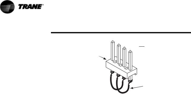
4.Internal module failure:
Internal module failures usually result only in communication loss to the failed module, but could, in some cases, affect all the modules because the failed module may “lock up” the IPC bus and prevent all communications. The former can be identified by analyzing all of the active IPC diagnostics. The latter can be identified in a process of elimination, whereby each module, in turn, is taken out of the IPC link and a jumper installed in its place. See Figure 3. The CPM can then be reset and the new IPC diagnostics that result can be analyzed.
RLC-SVD03A-EN |
11 |
Interprocessor Communication
-
$03 F F KHDGHU SLQV RU HTXLY
:LUH MXPSHUV VROGHUHG RU ZUDSSHG LQWR SLQV
Figure 3 IPC Jumper For Bypassing Modules (to be inserted into MTA connector in place of module)
5.Improper connections to terminal J2:
Jack J2, present on all modules except CLD, should have no connections. This input is for manufacturing test purposes only and any connections, shorts, etc. will potentially cause the module to not respond, respond to the wrong address, or (in the case of the CPM) fail to initiate any communications and thus fail the entire IPC.
6.High levels of Electro-Magnetic Interference:
The modules and the IPC have been qualified under severe EMI (both radiated and conducted) and the system was determined to be immune to all but extremely high noise levels. Always be sure to close and latch the control panel cabinet doors as the panel enclosure provides significant shielding and is integral in the overall noise immunity of the control system.
7.Module specific function selected without the Options Module:
If any of the functions on the Options Module are selected but the Options Module is not present, the UCM will look for this module and generate an error. The Options Module functions include Chilled Water Reset, Ice Machine Control, External Chilled Water Setpoint, External Current Limit Setpoint, and Tracer/Summit Communications.
Troubleshooting Procedure
1.Place the CPM in “Stop”. Record the active IPC diagnostics as shown in the Diagnostics Report of the CLD. The communication failure diagnostics and their meanings are shown in IPC Diagnostics of the RTAA-IOM-4 manual.
2.Determine which modules are not talking. These modules must be affected by one of the previously stated problems. If there is a group of modules not talking, suspect a wiring problem early in the daisy chain link. If only one module is not talking, suspect a loss of power or blown fuse.
12 |
RLC-SVD03A-EN |

Interprocessor Communication
3.Determine which modules are still talking. Wiring up to these is likely to be OK.
4.Try disconnecting the link or jumping out modules in the link at various places (use Figure 1). Reset the diagnostics and note which diagnostics reappear.
Here are some examples of IPC diagnostics:
Diagnostics present:
Chiller Mod Indicating EXV Mod Communications
Cprsr A Indicating EXV Mod Communications
Cprsr B Indicating EXV Mod Communications
The CPM and both MCSP modules are detecting a loss of communications with the EXV. Suspect power to the EXV or its fuse or a wiring problem downstream of the MCSP A and B modules.
Diagnostics present:
Chiller Mod Indicating Options Mod Communications
Chiller Mod Indicating EXV Mod Communications
Chiller Mod Indicating Cprsr A Communications
Chiller Mod Indicating Cprsr B Communications
The CPM is reporting that it cannot talk to any of the other modules. Suspect a shorted IPC bus or a module locking up the bus. The CPM could also be bad and not be sending recognizable tokens. Discriminating between these possibilities is done by disconnecting the link or jumping out modules in the link at various places. Refer to Item 4 in Troubleshooting Modules (Troubleshooting Modules Using IPC Diagnostics on page 9) for the procedure and the IPC Jumper for bypassing the Modules.
Diagnostics present:
Chiller Mod Indicating Cprsr B Communications
EXV Mod Indicating Cprsr B Communications
The CPM and EXV have both detected a communication loss with MCSP B. Suspect the address switch on MCSP B or a power/fuse problem.
Diagnostics present:
Chiller Mod Indicating Cprsr A Communications
Chiller Mod Indicating Cprsr B Communications
EXV Mod Indicating Cprsr A Communications
EXV Mod Indicating Cprsr B Communications
The CPM and EXV have both detected a communication loss with MCSP A and MCSP B. Suspect that the address switches on both modules are set to the same address. Wiring is probably OK since the EXV can talk to the CPM.
Diagnostics present:
Chiller Mod Indicating Cprsr B Communications
Chiller Mod Indicating Cprsr A Communications
Chiller Mod Indicating EXV Mod Communications
RLC-SVD03A-EN |
13 |

Interprocessor Communication
The CPM has detected loss of communications with MCSP A, MCSP B, and EXV. Suspect an open early in the IPC link between the CPM and MCSP B.
There are a large number of possible combinations of diagnostics. One must deduce what is causing the problem using all available information.
If the CLD Comm link to the CPM is broken, the message is:
No Communication, Data Not Valid
14 |
RLC-SVD03A-EN |

Temperature Sensor Checkout
With the exception of the thermostats located in the motor windings of the screw compressors, all the temperature sensors used on the UCMs are negative temperature coefficient (NTC) thermistors. The thermistors employed all have a base resistance of 10 Kohms at 77F (25C) and display a decreasing resistance with an increasing temperature. The UCMs “read” the temperature by measuring the voltage developed across the thermistors in a voltage divider arrangement with a fixed internal resistance. The value of this “pull-up” resistor is different depending on the temperature range where the most accuracy is desired. The voltage source for this measurement is a closely regulated 5.0 VDC supply.
An open or shorted sensor will cause the UCM to indicate the appropriate diagnostic. In most cases, an open or short will cause a CMR or MMR diagnostic that will result in a machine or circuit shutdown. Open or shorts on less critical Outdoor Air or Zone Temperature sensors will result in an Informational Warning Diagnostics and the use of default values for
that parameter.
Temperature Sensor Checkout Procedure
WARNING
Live Electrical Components!
During installation, testing, servicing and troubleshooting of this product, it may be necessary to work with live electrical components. Have a qualified licensed electrician or other individual who has been properly trained in handling live electrical components perform these tasks. Failure to follow all electrical safety precautions when exposed to live electrical components could result in death or serious injury.
1.Measure the temperature at the sensor using an accurate thermometer. Record the temperature reading observed.
2.With the sensor leads connected to the UCM and the UCM powered, measure the DC voltage across the sensor leads at the terminal or probe the back of the MTA plug.
NOTE: Always use a digital volt-ohmmeter with 10 megohm or greater input impedance to avoid “loading down” the voltage divider. Failure to do so will result in erroneously high temperature calculations.
3.Locate the appropriate sensor table. Table 3: Evaporator Water and Refrigerant Temperature Sensors, Table 4: Saturated Condenser Refrigerant and Entering Oil Temperature Sensors. Then compare the temperature in the table corresponding to the voltage reading recorded in Step 2 with the actual temperature observed in Step 1. If the actual temperature measured falls within the allowable tolerance range, both the sensor and the UCM's temperature input circuits are operating properly. However, if the actual temperature is outside the allowable sensor tolerance range, proceed to Step 4.
RLC-SVD03A-EN |
15 |

Temperature Sensor Checkout
4.Again measure the temperature at the sensor with an accurate thermometer; record the temperature reading observed.
5.Remove the sensor leads from the terminal strip or unplug the respective MTA. Measure the resistance of the sensor directly or probe the MTA with a digital volt-ohmmeter. Record the resistance observed.
6.Next, with the sensor still disconnected from the module, check the resistance from each of the sensor leads to the control panel chassis. Both readings should be more than 1 Megohm. If not, the sensor or the wiring to the sensor is either shorted or leaking to chassis ground and must be repaired.
7.Select the appropriate sensor table and locate the resistance value recorded in Step 5. Verify that the temperature corresponding to this resistance value matches (i.e. within the tolerance range specified for that sensor) the temperature measured in Step 4.
8.If the sensor temperature is out of range, the problem is either with the sensor, wiring, or the MTA connector (if applicable). If an MTA connector is used and the thermistor reads open, first try cutting off the MTA, stripping a small amount of insulation from the sensor wire's end and repeating the measurement directly to the leads. Once the fault has been isolated in this manner, install a new sensor, connector or both. When replacing a sensor, it is easiest to cut the sensor wire near the MTA end and splice on a new sensor using wire nuts.
9.A decade box can be substituted for the sensor and any sensor table value used to relate resistance to temperature. By removing the MTA plug and applying the resistance to the proper pin terminals, the temperature, as sensed by the UCM, can be confirmed. Using the CLD menu displays, scroll to the display of the temperature of interest.
NOTE: All displayed temperatures are slew rate limited and only accurate within a specified normal range. It is therefore important to be certain that the temperature readings are stable and that adequate time, up to 1 minute, is allowed after step changes in resistance inputs are made.
10.In all instances where module replacement is indicated, first perform the power supply/fuse check according to the information in the section “Module Power and Miscellaneous I/O” starting on page 41.
16 |
RLC-SVD03A-EN |

Temperature Sensor Checkout
.
Table 3 Sensor Conversion Data: Outdoor Air (6RT3), Entering and Leaving Evap Water Temp Matched Pairs (6RT7, 6RT8), and Saturated Evap and Comp Suction Refrigeration Temp (6RT9, 3B1RT5; 6RT10, 4B1RT6)
Actual |
Actual |
Thermistor |
Actual |
Actual |
Thermistor |
Actual |
Actual |
Thermistor |
Temp. |
Resistance |
Voltage |
Temp. |
Resistance |
Voltage |
Temp. |
Resistance |
Voltage |
(F) |
(Ohms) |
(Volts DC) |
(F) |
(Ohms) |
(Volts DC) |
(F) |
(Ohms) |
(Volts DC) |
-20.0 |
170040.3 |
4.448 |
30.0 |
34838.9 |
3.120 |
80.0 |
9297.5 |
1.533 |
-19.0 |
164313.4 |
4.434 |
31.0 |
33833.3 |
3.086 |
81.0 |
9075.9 |
1.509 |
|
|
|
|
|
|
|
|
|
-18.0 |
158796.5 |
4.414 |
32.0 |
32861.4 |
3.047 |
82.0 |
8860.2 |
1.484 |
|
|
|
|
|
|
|
|
|
-17.0 |
153482.9 |
4.395 |
33.0 |
31935.3 |
3.018 |
83.0 |
8650.4 |
1.460 |
-16.0 |
148365.0 |
4.380 |
34.0 |
31038.7 |
2.983 |
84.0 |
8446.2 |
1.436 |
|
|
|
|
|
|
|
|
|
-15.0 |
143432.2 |
4.360 |
35.0 |
30170.5 |
2.949 |
85.0 |
8247.5 |
1.411 |
-14.0 |
138679.6 |
4.341 |
36.0 |
29329.5 |
2.910 |
86.0 |
8054.1 |
1.387 |
|
|
|
|
|
|
|
|
|
-13.0 |
134098.6 |
4.321 |
37.0 |
28515.0 |
2.876 |
87.0 |
7865.8 |
1.362 |
-12.0 |
129684.9 |
4.302 |
38.0 |
27725.9 |
2.842 |
88.0 |
7682.5 |
1.343 |
|
|
|
|
|
|
|
|
|
-11.0 |
125428.5 |
4.282 |
39.0 |
26961.4 |
2.808 |
89.0 |
7504.2 |
1.318 |
|
|
|
|
|
|
|
|
|
-10.0 |
121326.1 |
4.263 |
40.0 |
26220.8 |
2.773 |
90.0 |
7330.5 |
1.294 |
-9.0 |
117369.6 |
4.238 |
41.0 |
25503.0 |
2.739 |
91.0 |
7161.4 |
1.274 |
|
|
|
|
|
|
|
|
|
-8.0 |
113554.9 |
4.219 |
42.0 |
24807.5 |
2.705 |
92.0 |
6996.7 |
1.250 |
-7.0 |
109876.5 |
4.194 |
43.0 |
24133.3 |
2.671 |
93.0 |
6836.3 |
1.230 |
|
|
|
|
|
|
|
|
|
-6.0 |
106328.1 |
4.175 |
44.0 |
23479.7 |
2.637 |
94.0 |
6680.1 |
1.211 |
-5.0 |
102904.9 |
4.150 |
45.0 |
22846.1 |
2.603 |
95.0 |
6528.0 |
1.187 |
-4.0 |
99602.3 |
4.126 |
46.0 |
22231.9 |
2.568 |
96.0 |
6379.8 |
1.167 |
|
|
|
|
|
|
|
|
|
-3.0 |
96416.1 |
4.106 |
47.0 |
21636.2 |
2.534 |
97.0 |
6235.5 |
1.147 |
|
|
|
|
|
|
|
|
|
-2.0 |
93341.6 |
4.082 |
48.0 |
21058.7 |
2.505 |
98.0 |
6094.8 |
1.128 |
|
|
|
|
|
|
|
|
|
-1.0 |
90374.2 |
4.058 |
49.0 |
20498.4 |
2.471 |
99.0 |
5957.8 |
1.108 |
0.0 |
87510.3 |
4.033 |
50.0 |
19955.0 |
2.437 |
100.0 |
5824.3 |
1.089 |
1.0 |
84745.9 |
4.004 |
51.0 |
19427.9 |
2.402 |
101.0 |
5694.2 |
1.069 |
2.0 |
82077.1 |
3.979 |
52.0 |
18916.5 |
2.368 |
102.0 |
5567.4 |
1.050 |
|
|
|
|
|
|
|
|
|
3.0 |
79500.5 |
3.955 |
53.0 |
18420.3 |
2.334 |
103.0 |
5443.8 |
1.030 |
4.0 |
77012.3 |
3.926 |
54.0 |
17938.8 |
2.305 |
104.0 |
5323.3 |
1.016 |
5.0 |
74609.7 |
3.901 |
55.0 |
17471.6 |
2.271 |
105.0 |
5205.9 |
0.996 |
6.0 |
72288.8 |
3.872 |
56.0 |
17018.0 |
2.236 |
106.0 |
5091.5 |
0.977 |
|
|
|
|
|
|
|
|
|
7.0 |
70047.4 |
3.848 |
57.0 |
16577.8 |
2.207 |
107.0 |
4979.9 |
0.962 |
|
|
|
|
|
|
|
|
|
8.0 |
67881.9 |
3.818 |
58.0 |
16150.5 |
2.173 |
108.0 |
4871.1 |
0.942 |
9.0 |
65790.2 |
3.789 |
59.0 |
15735.7 |
2.144 |
109.0 |
4765.0 |
0.928 |
|
|
|
|
|
|
|
|
|
10.0 |
63768.7 |
3.760 |
60.0 |
15332.9 |
2.109 |
110.0 |
4661.5 |
0.913 |
11.0 |
61815.3 |
3.730 |
61.0 |
14941.7 |
2.080 |
111.0 |
4560.6 |
0.894 |
|
|
|
|
|
|
|
|
|
12.0 |
59927.8 |
3.701 |
62.0 |
14561.9 |
2.046 |
112.0 |
4462.2 |
0.879 |
13.0 |
58103.1 |
3.672 |
63.0 |
14193.0 |
2.017 |
113.0 |
4366.3 |
0.864 |
|
|
|
|
|
|
|
|
|
14.0 |
56339.6 |
3.643 |
64.0 |
13834.6 |
1.987 |
114.0 |
4272.6 |
0.850 |
|
|
|
|
|
|
|
|
|
15.0 |
54634.7 |
3.608 |
65.0 |
13486.5 |
1.958 |
115.0 |
4181.3 |
0.835 |
16.0 |
52986.4 |
3.579 |
66.0 |
13148.3 |
1.924 |
116.0 |
4092.2 |
0.820 |
|
|
|
|
|
|
|
|
|
17.0 |
51392.6 |
3.550 |
67.0 |
12819.8 |
1.895 |
117.0 |
4005.3 |
0.806 |
18.0 |
49851.6 |
3.516 |
68.0 |
12500.5 |
1.865 |
118.0 |
3920.5 |
0.791 |
|
|
|
|
|
|
|
|
|
19.0 |
48360.9 |
3.486 |
69.0 |
12190.2 |
1.836 |
119.0 |
3837.7 |
0.776 |
20.0 |
46919.2 |
3.452 |
70.0 |
11888.7 |
1.807 |
120.0 |
3756.9 |
0.762 |
21.0 |
45524.6 |
3.418 |
71.0 |
11595.6 |
1.777 |
121.0 |
3678.1 |
0.747 |
|
|
|
|
|
|
|
|
|
22.0 |
44175.6 |
3.389 |
72.0 |
11310.7 |
1.753 |
122.0 |
3601.1 |
0.732 |
|
|
|
|
|
|
|
|
|
23.0 |
42870.3 |
3.354 |
73.0 |
11033.7 |
1.724 |
123.0 |
3526.5 |
0.723 |
|
|
|
|
|
|
|
|
|
24.0 |
41607.6 |
3.320 |
74.0 |
10764.4 |
1.694 |
124.0 |
3453.6 |
0.708 |
25.0 |
40385.3 |
3.286 |
75.0 |
10502.6 |
1.670 |
125.0 |
3382.4 |
0.698 |
26.0 |
39202.7 |
3.257 |
76.0 |
10248.0 |
1.641 |
126.0 |
3313.0 |
0.684 |
27.0 |
38057.9 |
3.223 |
77.0 |
10000.4 |
1.616 |
127.0 |
3245.1 |
0.674 |
|
|
|
|
|
|
|
|
|
28.0 |
36950.0 |
3.188 |
78.0 |
9759.6 |
1.587 |
128.0 |
3178.9 |
0.659 |
29.0 |
35877.4 |
3.154 |
79.0 |
9525.4 |
1.563 |
129.0 |
3114.2 |
0.649 |
|
|
|
|
|
|
130.0 |
3051.0 |
0.635 |
1.Overall accuracy for any of the sensors is at least + 2 F over the range shown. Accuracy of matched sensors is + 1 F over specific ranges.
2.As you compare a thermistor resistance (or input voltage) reading with the “actual” temperature indicated by the thermometer, be sure to consider the precision and location of the thermometer when you decide whether or not the thermistor is out of specified accuracy.
3.The thermistor resistances given do not account for the self-heating effects that are present when connected to the UCM. A connected “operating” thermistor will read a slightly lower (less than 1%) resistance.
RLC-SVD03A-EN |
17 |

Temperature Sensor Checkout
Table 4 Sensor Conversion Data: Saturated Condenser and Entering Oil Temperature Matched Pairs (6RT12, 3B1RT1; 6RT13, 4B1RT2)
Actual |
Actual |
Thermistor |
Actual |
Actual |
Thermistor |
Actual |
Actual |
Thermistor |
Temp. |
Resistance |
Voltage |
Temp. |
Resistance |
Voltage |
Temp. |
Resistance |
Voltage |
(F) |
(Ohms) |
(Volts DC) |
(F) |
(Ohms) |
(Volts DC) |
(F) |
(Ohms) |
(Volts DC) |
0.0 |
87510.3 |
4.651 |
50.0 |
19955.0 |
3.765 |
100.0 |
5824.3 |
2.356 |
1.0 |
84745.9 |
4.641 |
51.0 |
19427.9 |
3.740 |
101.0 |
5694.2 |
2.327 |
|
|
|
|
|
|
|
|
|
2.0 |
82072.1 |
4.630 |
52.0 |
18916.5 |
3.715 |
102.0 |
5567.4 |
2.300 |
|
|
|
|
|
|
|
|
|
3.0 |
79500.1 |
4.619 |
53.0 |
18420.3 |
3.689 |
103.0 |
5443.8 |
2.272 |
4.0 |
77012.3 |
4.608 |
54.0 |
17938.8 |
3.664 |
104.0 |
5323.3 |
2.244 |
|
|
|
|
|
|
|
|
|
5.0 |
74609.7 |
4.596 |
55.0 |
17471.6 |
3.638 |
105.0 |
5205.9 |
2.217 |
6.0 |
72288.8 |
4.584 |
56.0 |
17018.0 |
3.611 |
106.0 |
5091.5 |
2.189 |
|
|
|
|
|
|
|
|
|
7.0 |
70047.4 |
4.572 |
57.0 |
16577.8 |
3.585 |
107.0 |
4979.9 |
2.162 |
|
|
|
|
|
|
|
|
|
8.0 |
67881.9 |
4.560 |
58.0 |
16150.5 |
3.558 |
108.0 |
4871.1 |
2.135 |
|
|
|
|
|
|
|
|
|
9.0 |
65790.2 |
4.547 |
59.0 |
15735.7 |
3.531 |
109.0 |
4765.0 |
2.108 |
|
|
|
|
|
|
|
|
|
10.0 |
63768.7 |
4.534 |
60.0 |
15332.9 |
3.504 |
110.0 |
4661.5 |
2.082 |
11.0 |
61815.3 |
4.521 |
61.0 |
14941.7 |
3.477 |
111.0 |
4560.6 |
2.055 |
|
|
|
|
|
|
|
|
|
12.0 |
59927.8 |
4.507 |
62.0 |
14561.9 |
3.450 |
112.0 |
4462.2 |
2.029 |
13.0 |
58103.1 |
4.494 |
63.0 |
14193.0 |
3.422 |
113.0 |
4366.3 |
2.003 |
|
|
|
|
|
|
|
|
|
14.0 |
56339.6 |
4.479 |
64.0 |
13834.6 |
3.394 |
114.0 |
4272.6 |
1.977 |
15.0 |
54634.7 |
4.465 |
65.0 |
13486.5 |
3.366 |
115.0 |
4181.3 |
1.951 |
16.0 |
52986.4 |
4.450 |
66.0 |
13148.3 |
3.338 |
116.0 |
4092.2 |
1.926 |
|
|
|
|
|
|
|
|
|
17.0 |
51392.6 |
4.435 |
67.0 |
12819.8 |
3.310 |
117.0 |
4005.3 |
1.901 |
|
|
|
|
|
|
|
|
|
18.0 |
49851.6 |
4.420 |
68.0 |
12500.5 |
3.282 |
118.0 |
3920.5 |
1.876 |
|
|
|
|
|
|
|
|
|
19.0 |
48360.9 |
4.404 |
69.0 |
12190.2 |
3.253 |
119.0 |
3837.7 |
1.851 |
20.0 |
46919.2 |
4.388 |
70.0 |
11888.7 |
3.225 |
120.0 |
3756.9 |
1.826 |
21.0 |
45524.6 |
4.372 |
71.0 |
11595.6 |
3.196 |
121.0 |
3678.1 |
1.802 |
22.0 |
44175.6 |
4.355 |
72.0 |
11310.7 |
3.167 |
122.0 |
3601.1 |
1.777 |
|
|
|
|
|
|
|
|
|
23.0 |
42870.3 |
4.338 |
73.0 |
11033.7 |
3.139 |
123.0 |
3526.5 |
1.754 |
24.0 |
41607.6 |
4.321 |
74.0 |
10764.4 |
3.110 |
124.0 |
3453.6 |
1.730 |
25.0 |
40385.3 |
4.303 |
75.0 |
10502.6 |
3.081 |
125.0 |
3382.4 |
1.707 |
26.0 |
39202.7 |
4.285 |
76.0 |
10248.0 |
3.051 |
126.0 |
3313.0 |
1.684 |
|
|
|
|
|
|
|
|
|
27.0 |
38057.9 |
4.266 |
77.0 |
10000.0 |
3.022 |
127.0 |
3245.1 |
1.661 |
|
|
|
|
|
|
|
|
|
28.0 |
36950.0 |
4.248 |
78.0 |
9759.6 |
2.993 |
128.0 |
3178.9 |
1.638 |
29.0 |
35877.4 |
4.229 |
79.0 |
9525.4 |
2.964 |
129.0 |
3114.2 |
1.615 |
|
|
|
|
|
|
|
|
|
30.0 |
34838.9 |
4.209 |
80.0 |
9297.5 |
2.935 |
130.0 |
3051.0 |
1.593 |
31.0 |
33833.3 |
4.190 |
81.0 |
9075.9 |
2.905 |
131.0 |
2989.2 |
1.571 |
|
|
|
|
|
|
|
|
|
32.0 |
32861.4 |
4.170 |
82.0 |
8860.2 |
2.876 |
132.0 |
2928.9 |
1.549 |
33.0 |
31935.3 |
4.150 |
83.0 |
8650.4 |
2.847 |
133.0 |
2870.0 |
1.528 |
|
|
|
|
|
|
|
|
|
34.0 |
31038.7 |
4.130 |
84.0 |
8446.2 |
2.817 |
134.0 |
2812.4 |
1.506 |
|
|
|
|
|
|
|
|
|
35.0 |
30170.5 |
4.109 |
85.0 |
8247.5 |
2.788 |
135.0 |
2756.2 |
1.485 |
36.0 |
29329.5 |
4.088 |
86.0 |
8054.1 |
2.759 |
136.0 |
2701.2 |
1.464 |
|
|
|
|
|
|
|
|
|
37.0 |
28515.0 |
4.067 |
87.0 |
7865.8 |
2.730 |
137.0 |
2647.5 |
1.444 |
38.0 |
27725.9 |
4.045 |
88.0 |
7682.5 |
2.700 |
138.0 |
2595.0 |
1.423 |
|
|
|
|
|
|
|
|
|
39.0 |
26961.4 |
4.024 |
89.0 |
7504.2 |
2.671 |
139.0 |
2543.7 |
1.403 |
40.0 |
26220.8 |
4.002 |
90.0 |
7330.5 |
2.642 |
140.0 |
2493.6 |
1.383 |
41.0 |
25503.0 |
3.979 |
91.0 |
7161.4 |
2.613 |
141.0 |
2444.6 |
1.364 |
42.0 |
24807.5 |
3.957 |
92.0 |
6996.7 |
2.584 |
142.0 |
2396.7 |
1.344 |
|
|
|
|
|
|
|
|
|
43.0 |
24133.3 |
3.934 |
93.0 |
6836.3 |
2.555 |
143.0 |
2349.9 |
1.325 |
|
|
|
|
|
|
|
|
|
44.0 |
23479.7 |
3.910 |
94.0 |
6680.1 |
2.526 |
144.0 |
2304.1 |
1.306 |
45.0 |
22846.1 |
3.887 |
95.0 |
6528.0 |
2.498 |
145.0 |
2259.2 |
1.287 |
46.0 |
22231.9 |
3.863 |
96.0 |
6379.8 |
2.469 |
146.0 |
2216.0 |
1.269 |
47.0 |
21636.2 |
3.839 |
97.0 |
6235.5 |
2.440 |
147.0 |
2172.8 |
1.250 |
|
|
|
|
|
|
|
|
|
48.0 |
21058.7 |
3.815 |
98.0 |
6094.8 |
2.412 |
148.0 |
2131.6 |
1.232 |
49.0 |
20498.4 |
3.790 |
99.0 |
5957.8 |
2.384 |
149.0 |
2090.4 |
1.215 |
|
|
|
|
|
|
150.0 |
2051.2 |
1.197 |
1.Overall accuracy for the sensor is at least + 2 F over the range shown.
2.As you compare a thermistor resistance (or input voltage) reading with the “actual” temperature indicated by the thermometer, be sure to consider the location and precision of the thermometer when you decide whether or not the thermistor is out of specified accuracy.
3.The thermistor resistances given do not account for the self-heating effects that are present when connected to the UCM. A connected “operating” thermistor will read a slightly lower (less than 1%) resistance.
18 |
RLC-SVD03A-EN |

Compressor Operation
This feature is called the Auto Lead/Lag and can be found in the Service Settings Group, under the “Balanced CPRSR Starts and Hours” menu. When this function is disabled, the UCM always starts compressor “A” first. When this function is enabled, the following occurs:
The UCM equalizes operating starts and hours. This will cause the compressor with the least amount of starts to be started first. When a compressor starts, it is always started unloaded.
When a compressor is stopped, it shuts down in an unloaded state, unless taken out by a manual reset diagnostic.
When the first compressor is brought on line, it attempts to meet the load by staging on the step load solenoid and by pulsing the male slide valve load solenoid. If one compressor cannot meet the load demand, the second compressor is brought on line. It also attempts to meet the load demand by staging on its step load solenoid and by pulsing its male slide valve solenoid. When both compressors are running and both of their step load solenoids are energized, the male load and unload solenoids on both compressors are pulsed, thus modulating their respective slide valves to balance the load. The UCM attempts to distribute the load evenly between the two compressors. When the load drops off, the compressor with the most hours will always be the first to unload and turn off. The anti-recycle timer is approximately 5 minutes from start to start. The minimum time between compressor shutdown and restart is approximately 10 seconds, but only if the compressor has been running over 5 minutes or longer prior to shutting down on temperature. Otherwise, it is the remaining portion of the 5 minutes.
Restart Inhibit Timer
If compressor operation is interrupted by an extended (not momentary) loss of power or a manual reset, there will be a two minute delay between the power up or manual reset and the start of a compressor, assuming there is a call for cooling. The timer is factory set at 2 minutes but can be field adjusted from 30 seconds to two minutes in the Service Settings Group.
RLC-SVD03A-EN |
19 |

Compressor Start/Stop
To start a compressor after either a “normal' shutdown, a Diagnostic reset, or power-on-reset, the following sequence will occur:
1.On a call for a compressor, the Restart Inhibit Timer will time out, if any time remains.
2.The EXV is positioned to the initial closed start position. At the same time, the unload solenoid is energized and the load solenoid is de-ener- gized. Timing is determined by the time required to position the EXV
3.After the EXV is positioned:
•the compressor is turned on
•the compressor heater is de-energized
•the saturated evaporator ref. temp. cutout ignore time is set, based on the saturated condenser temperature. Prior to start, the condenser temperature approximates the ambient temperature.
•the fan control algorithm is executed
To stop a compressor due to either the Stop button on the CLD or an External/Remote “STOP”, the sequence shall be as follows:
1.The unload solenoid is energized for 20 seconds and the load solenoid is de-energized. The compressor continues to run for the remaining 20 seconds. This is defined as the RUN:UNLOAD mode.
2.The compressor and the fans are turned off. The crankcase heater is energized.
3.The unload solenoid remains energized for 60 minutes after the compressor stops. The load solenoid is de-energized.
4.The EXV is closed. Closing begins at maximum speed when the compressor is turned off. (Max. speed is 25 steps per second, full stroke is 757 steps.
5.After 60 minutes, the unload solenoid de-energizes.
The RUN:UNLOAD mode is also used to stop a compressor due to normal LWT control, Low Ambient Run Inhibit, or Freeze Avoidance.
A compressor stop due to any diagnostic will skip step 1 above and go directly to step 2.
20 |
RLC-SVD03A-EN |
Variable Speed
Inverter/Condenser Fan Control
When Fan Control and Variable Speed Fan (VSF) are set to Enable in the Machine Configuration Menu, the UCM will control both the variable speed fan and the remaining constant speed fans per the VSF Control Algorithm. If VSF Control is disabled for a given circuit but Fan Control is enabled for the machine, the circuit will perform normal constant speed fan control. The VSF is enabled and operational, the control attempts to provide a 70 ± 5 psid between the Condenser Pressure and the Evaporator Pressure (as derived from the temperature sensor measurements).
23(5$7,1*
35(6685(
',))(5(17,$/
36,'
1RQ $GMXVWDEOH 'LII 3UHVV 6HWSRLQW
/RDG 6WHS
&035
0LQ /RDG
67$7(
2II
3DQLF )DQ$GGV
$GGLWLRQDO )DQVLI DYDLODEOH DUHLPPHGLDWHO\ VWDUWHGDW HDFK FRQGHQVHUWHPSHUDWXUH VKRZQ
96) 3,' ,QFUHDVLQJ )DQ 6SHHG
96) 3,' 'HFUHDVLQJ )DQ 6SHHG
+LJK 'LIIHUHQWLDO 3UHVVXUH /RFNRXW $UHD 'LDJQRVWLF 2FFXUV ZKHQ'HOWD 3 LV ! 36,' DQG LQWHJUDO H[FHHGV 36, PLQXWHV
6WDUW 8S )DQ 6WDWH
)DQV 96) PLQ VSHHG
$PELHQW )DQV 96) PLQ VSHHG
7HPS
)DQV 96) PLQ VSHHG
'HJUHHV )
)DQ 96) PLQ VSHHG
9DU 6SG )DQ RQO\ PLQ VSHHG
$QWLFLSDWRU\ )DQ &RQWURO )XQFWLRQ
|
|
,Q WKLV DUHD VWDUW D IDQ ZLWK |
|||||||
2SHUDWLQJ |
|
D FRPSUHVVRU VWHS EXW |
|||||||
|
WDNH QR DFWLRQ ZLWK XQVWHS |
||||||||
3UHVVXUH |
|
|
|
|
|
|
|
|
|
'LIIHUHQWLDO |
|
|
|
,Q WKLV DUHD DOZD\V VWDUW |
|||||
36,' |
|
|
|
RU VWRS D IDQ ZLWK D |
|||||
|
|
|
|||||||
|
|
FRPSUHVVRU VWHS RU XQVWRS |
|||||||
|
|
|
|
|
|
|
|
|
|
|
|
|
|
|
|
|
|
|
|
|
|
|
|||||||
|
|
|
(YDS /HDYLQJ :DWHU 7HPS ) |
||||||
|
96) DW PD[ VSHHG |
VHF |
|
|
|
6WDJH RQ QH[W &RQVWDQW |
|
|
|
|
|
|
|
|
|
|
|
|
|
VSHHG )DQ GXH WR 96) |
96) DW PD[ VSHHG |
|
|
6WDJH RQ QH[W &RQVWDQW |
|
||||
|
|
|
|
|
|
|
|
|
||||||
|
,QYHUWHU )DQ 0D[ 5DPS |
|
|
|
|
DW PD[ 6SHHG |
|
|
|
|||||
|
|
|
|
|
|
|
|
VHF |
|
VSHHG )DQ GXH WR 96) |
|
|||
|
|
|
|
|
|
|
|
|
||||||
UDWH LV +] VHF |
|
|
|
|
|
|
|
|
|
|
DW PD[ 6SHHG |
|
||
|
'HDG%DQG 36,' |
|
|
|
|
|
|
|
|
|
|
|
|
|
|
'HDG%DQG 36,' |
|
|
|
|
|
|
|
|
|
|
|
|
|
|
|
|
|
|
|
|
|
|
|
|
|
|
|
6WDJH RII )DQ GXH WR &RPSUHVVRU |
|
|
|
|
|
|
|
|
|
|
|
|
|
|
|
|
|
|
|
|
|
|
|
6WDJH RQ QH[W )DQ |
|
|
||||
|
|
|
|
|
|
|
|
|
|
|||||
|
|
|
|
|
|
|
|
|
|
ORDG 6WHS 6HH $QWLFLSDWRU\ |
||||
|
%HJLQ 3HU 6WDUW 8S )DQ 6WDWH |
|
|
|
GXH WR &RPSUHVVRU |
|
|
|||||||
|
|
'HFUHDVH VSHHG RI 96) |
|
|
)DQ &RQWURO LQVHW DERYH |
|||||||||
|
|
ORDG 6WHS 6HH $QWLFLSDWRU\ |
||||||||||||
|
6HH LQVHW DERYH |
|
|
|
|
|||||||||
|
|
|
|
|
WR PDNH XS IRU DGGHG IDQ |
)DQ &RQWURO LQVHW DERYH |
|
|
|
|||||
|
|
|
|
|
|
|
|
|
||||||
/RZ 'LIIHUHQWLDO 3UHVVXUH /RFNRXW $UHD 'LDJQRVWLF 2FFXUV LI 'HOWD 3 LV 36,' IRU PLQXWHV
7,0(
Figure 4 Variable Speed Fan (VSF) and Fan Staging Control
The VSF Inverter is commanded to a given speed by the UCM, using a PWM (Pulse Width Modulated) signal (10V, 15mA, 10 Hz Fundamental) with a duty cycle proportional to the desired voltage and frequency from the Inverter. The UCM also controls power to the Inverter through a contactor. The Inverter Contactor for the respective circuit is energized approximately 20 seconds prior to compressor start on that circuit. The VSF Control algorithm runs on a 5-second interval and is limited to a commanded rate of change of no greater than 40% of full speed per interval. The same algorithm that controls the
RLC-SVD03A-EN |
21 |

Variable Speed Inverter/
Condenser Fan Control
speed will also cause constant speed fans to stage On and Off when the inverter is commanded to full speed and minimum speed respectively. The stage On (or Off) of a constant speed fan will occur if the inverter speed command is at max (or min.) for three consecutive intervals (15 seconds).
Outdoor Air Temperature and Fan Control
Outdoor air temperature is used to provide a reasonable startup state. Using this temperature, the algorithm automatically determines the number of constant speed fans to turn on immediately at compressor start. The outdoor air temperature sensor is also used to anticipate new states during normal running to minimize pressure upsets. This anticipation is based on the staging and unstaging of compressor steps at given leaving water temperatures. In this way, precise airflow can be maintained, allowing for stable differential pressures under part load and low ambient conditions.
VSF Inverter Fault
A fault signal will be sent to the UCM from the Inverter when it has gone through a self-shutdown or if the output frequency of the Inverter is being limited to less than 50% of the signal speed commanded by the UCM. Upon receipt of the fault signal, the UCM shall attempt to reset the fault by sending a 0 PWM command to the Inverter for a total of five seconds. The fault signal will again be checked and repeated if still in fault. If four faults are detected within one minute of each other, the power to the Inverter will be cycled off for 30 seconds (through contactor control) and then re-powered. If the fault still remains or occurs again within one minute, an IFW diagnostic occurs. The UCM will remove power from the Inverter and attempt to run the remaining constant-speed fans using normal constant-speed Fan Control Algorithm. See page 80 for step-by-step troubleshooting procedure.
22 |
RLC-SVD03A-EN |

Current Transformer
Each compressor motor has all three of its line currents monitored by torroid (doughnut) current transformers. While the MCSP utilizes all three of the signals, it only displays the maximum phase at any given time. These currents are normalized with respect to the Rated Load Amps of the respective compressor and thus are expressed in terms of % (percent) RLA. The currents are “normalized” thru the proper selection of the Current Transformer, the setting of the Compressor Current Overload dip switch (SW2) on the MCSPs, and the redundant programming of the decimal equivalent of these settings in the Service Settings Group of the CLD. (The term “Compressor Current Overload setting” is actually a misnomer. Instead the setting should be thought of as an internal software gain that normalizes the currents to a % RLA for a given CT and compressor rating. The true nominal steady state overload setting is fixed at 132%). Refer to Tables 5 thru 9 for setup details.
The current transformers provide the input for six basic functions of the MCSP:
1.Motor overload protection using a programmed “% RLA versus time to trip” characteristic. Refer to Table 6 for details. The steady state “must trip” value is 140% RLA and the “must hold” value is 125% RLA. The MCSP will trip out the compressor. The appropriate diagnostic descriptions are then displayed in the CLD diagnostic section.
2.Verifying contactor drop-out. If currents corresponding to less than 12 ±7% RLA are not detected on all three of the monitored compressor phases within approximately 5 seconds after an attempted contactor drop-out, the compressor will continue to be commanded Off, the Unload solenoid will be pulsed, the EXV will be opened to its fullest position, and the fans will continue to be controlled. This condition will exist until the diagnostic is manually reset.
3.Loss of Phase Current. If the detection of any or all of the three motor phase currents falls below 12 ±7% RLA for 2 ±1 seconds while the branch circuit should be “energized”, the MCSP will trip out the compressor. The Phase Loss diagnostic, or the Power Loss diagnostic, will be displayed. Failure of a contactor to pull in will cause the Phase Loss diagnostic. However when reduced voltage starting is employed, it may take an additional 3 seconds to detect a phase loss at startup, as phase loss protection is not active during the 3 second transition time.
4.Phase Rotation. Screw compressors cannot be allowed to run in reverse direction. To protect the compressors, the phase rotation is detected by the current transformers immediately at start up. If improper phasing is detected, within 1 second of startup, the MCSP will trip out the compressor. The Phase Rotation diagnostics will be displayed. This function is not sensitive to the current transformer's polarity.
5.Phase Unbalance. The MCSP will shut down the compressor if a phase current unbalance is detected by the current transformers while the compressor is running. A 15% unbalance, if protection is enabled, will cause the MCSP to trip out the compressor. The Phase Unbalance diagnostics
RLC-SVD03A-EN |
23 |

Current Transformer
will be displayed. If this protection is disabled, a 30% phase unbalance will still be in effect with the diagnostic code Severe Phase Imbalance being displayed.
6.Current Limit. The MCSP will begin to unload its compressor as the %RLA exceeds 120%. Further, the CPM will cause the compressors to automatically unload when the Chiller Current Limit Setpoint is reached. The Current Limit Setpoint is set in the Service Setting Group. Individual compressor phase currents are averaged and added together to compare to the Chiller Current Limit which is in terms of % Total of all of the Compressor RLNs.
NOTE: The current transformers are NOT polarity or directionally sensitive.
CT and MCSP Compressor Current Input Checkout
Procedure
WARNING
Live Electrical Components!
During installation, testing, servicing and troubleshooting of this product, it may be necessary to work with live electrical components. Have a qualified licensed electrician or other individual who has been properly trained in handling live electrical components perform these tasks. Failure to follow all electrical safety precautions when exposed to live electrical components could result in death or serious injury.
1.Check incoming 3-phase power for voltage within 10% of nominal per Chiller nameplate.
2.Interrogate the CPM for all of the presently active diagnostic codes or the historic diagnostic codes in the Diagnostics Menu. Narrow the problem down to a particular compressor or contactor as noted above. Write down all of the diagnostic codes stored in the diagnostic registers.
If there is any question as to which compressor or current transformer is causing a problem, or simply to verify and “witness” the problem, an attempt should be made to restart the chiller after clearing diagnostics. The diagnostics can be cleared by entering the Diagnostics Menu and stepping to the CLEAR DIAGNOSTICS display.
It is possible to “force” certain compressors to be the first or next compressor to stage on, using the “Compressor Test” feature in the Service Tests Menu. The Leaving Water Temperature must, however, be above the Chilled Water Setpoint by more than the “differential to start” setting, in order to stage on the first compressor.
At startup, verify the appropriate contactor(s) pull-in. The “Compressors On” menu item in the Chiller Report Group will indicate which compressor started approximately five seconds after the contactor pulls in. Note the diagnostic(s) that results, then place the Chiller into the “Stop” mode by depressing the Stop button on the CLD.
24 |
RLC-SVD03A-EN |

Current Transformer
WARNING
Hazardous Voltage w/Capacitors!
Disconnect all electric power, including remote disconnects before servicing. Follow proper lockout/tagout procedures to ensure the power cannot be inadvertently energized. For variable frequency drives or other energy storing components provided by Trane or others, refer to the appropriate manufacturer’s literature for allowable waiting periods for discharge of capacitors. Verify with an appropriate voltmeter that all capacitors have discharged. Failure to disconnect power and discharge capacitors before servicing could result in death or serious injury.
Note: For additional information regarding the safe discharge of capacitors, see PROD-SVB06A-EN or PROD-SVB06A-FR
3.For the next portion of the procedure, pull the unit's disconnect and interrupt all high voltage power to the control panel. Locate the torroid (doughnut) current transformers encircling the compressor power wiring and branching to the compressor contactors of the suspect compressor-in the control panel. Refer to the Component Location Drawing in the panel to identify the particular current transformer(s) of interest. Locate the part number/UL tag on the transformer leads and note the Trane part number which identifies the transformers. Note: all compressors of a given tonnage should have the same transformer extension number. Verify the proper current transformer using Table 5 in this section. Also check the setting of the dip switch (SW2) on each of the MCSP modules and verify these against Table 5 for each compressor. (Switch position SW2-1 is the Most Significant Bit). The decimal equivalent of this setting should also be verified in the Service Setting Group under the “CURRENT OVRLD SETTINGS” display. If the programmed value does not agree with the dip switch setting for each of the MCSP's, an informational diagnostic will result. The compressors will be allowed to run, but default settings (the most sensitive possible) will be used for the internal software compressor current gains.
4.Utilizing the Schematic Wiring Diagram, locate the termination of the transformer's wiring into the MTA plug at the appropriate MCSP module at pin header J5. Pull off the appropriate MTA connector from the pin header on the MCSP.
Current Transformers can be damaged and high voltages can result due to running the compressors without a suitable burden load for the CTs. This load is provided by the MCSP input. Take care to properly reconnect the CT's MTA prior to attempted start of the compressors.
5.Using a digital volt-ohmmeter, measure the resistance of the transformer(s) by probing the appropriate pair(s) of receptacles within the MTA. The receptacle pairs of the MTA are most easily measured by using meter leads with pointed probes and contacting the exposed metal of the connector through either the top or the side of the MTA. (It may be nec-
RLC-SVD03A-EN |
25 |

Current Transformer
essary to remove a cap over the top of the connector to gain access to the connector conductors.)
6.Refer to Table 7 which lists the normal resistance range for each extension of current transformer. Check the measured resistance against the value listed per transformer extension. If the resistance is within tolerance, the transformer and MTA can be considered good. Go on to step 8.
7.If the resistance reading above is out of tolerance, the problem is either with the transformer, its wiring, or the MTA connector. First double check the schematic to be sure you are working the proper lead pair. Then cut the leads to the particular transformer near the MTA connector and repeat the resistance measurement by stripping insulation from the wire's end. Once the fault has been isolated in this manner, reconnect leads or install a new transformer or connector.
More than one current transformer is terminated to a single MTA. When replacing, take care to note the proper positions of the respective transformer wire terminations on the MTA for the re-termination. The current transformers are NOT polarity or directionally sensitive. The transformer lead wiring is #22 AWG, UL 1015 600V and the proper MTA connector (red color code) must be used to ensure a reliable connection. If the fault can be isolated to the current transformer or its wiring apart from the connector, the connector can be reused by cutting off the bad transformer and splicing in a new transformer using wire nuts.
8.If the transformer/connector resistance proves accurate, recheck the resistance with the connector held at different angles and with a light lead pull (less than 5 lb.) to test for an intermittent condition.
9.To perform the following test, you will need to use a digital voltmeter with a diode test function,. With the transformer MTA disconnected and the power off to the MCSP, perform a diode test across the corresponding pair of current transformer input pins on the MCSP (header J5). The meter should read from 1.0 to 1.5 volts for each current transformer input. Repeat using the opposite polarity. The same reading should result. Extreme errors suggest a defective MCSP module. If the diode voltage drops prove accurate, reconnect the transformers to the MCSP and repower the unit.
10.With the CT's reconnected to the MCSP, attempt a restart of the chiller. As the given compressor is started, and the inrush locked rotor transient has passed, (locked rotor transient should last less than one second) simultaneously monitor the actual compressor phase current(s) (using a clamp-on type ammeter) and the voltage developed at the respective current transformer's termination at the MCSP (using a digital volt-meter on a 0-20 VAC scale). Refer to Table 8 for the compressor phase current to output voltage relationship for each extension current transformer. Using Table 8, look up to current that corresponds to the output voltage read by the voltmeter and compare to ammeter reading. Assuming relatively accurate meters, the values should agree to within 5%.
11.If the measured current and the output voltage from the CT agree within the tolerance specified, the CT is good. If diagnostics, overload trips, or other problems potentially involving current sensing continue to occur
26 |
RLC-SVD03A-EN |

Current Transformer
with all phase currents to the compressors verified to be within their normal range, then the problem is either with the CT selection, MCSP Compressor Overload Dip Switch Setting, or the MCSP's current input, analog to digital (A/D), or dip switch input circuitry. Since the first two items were verified in Step 2 using Table 5, that leaves only the MCSP circuitry as an issue. It is advisable to replace the MCSP module at this point. However if verification of the MCSP Current sensing operation is desired, go to step 12 below.
12.There are two ways that the MCSP's current sensing can be checked. Both methods use the CLD display of the %RLA from each MCSP (Compressor Report) for indication of the sensed current. The first is straightforward equation and assumes that the proper Compressor Overload dip switch setting and current transformer have been selected:
Measured Compr. amps of max. phase
%RLA =-------------------------------------------------------------------------------------------------------
Nameplate Compressor RLA
To check the displayed % RLA as a function of the output voltage from the current transformers (as connected at the MCSP), Tables 8 and 9 are utilized. In Table 8 look up (or interpolate) the “% of CT rating” corresponding to the maximum of the three CT Input Voltages (VAC rms) as read at the MCSP. (The table is necessary because the voltage developed at the MCSP is not linear with the CT's secondary current). Next, check the Compressor Current Overload setting of switch SW2 on the MCSP and find the corresponding “SOFTWARE GAIN” in Table 9. The % RLA displayed by the CPM should be:
%RLA = % CT Rating X SOFTWARE GAIN
The preceding equations should only be applied during steady state current draws (after transition). Inrush transient currents and associated CT output voltages can be expected to be from 3 to 6 times the steady state values, and the displayed value only reads up to 255% RLA. The accuracy of the displayed value should be within ± 5% of that predicted using the Input voltage. However, the end to end accuracy of the displayed value compared to the actual %RLA max. phase current is ± 3.3% over the range of 50 to 150% of CT rating.
13.If no phase currents are measured with the amprobe on any or all of the legs to a given compressor immediately following the attempted staging of that compressor by the MCSP, the problem lies either with the contactor, motor circuit or the MCSP relay outputs. Refer to MCSP Checkout Procedure in Compressor Module (MCSP) (1U4 AND 1U5) on page 72.
RLC-SVD03A-EN |
27 |
Loading...