


Installation, Owner, and
Diagnostic Manual
IntelliPak®
Commercial Self-Contained
Modular Series, 20-35 Ton
Models
“BO” and later Design Sequence
SCWG -020, -025, -030, -035
SIWG -020, -025, -030, -035
SCRG -020, -025, -032
SIRG -020, -025, -032
July 2000
SCXG-SVX01B-EN
General
Information
About This Manual
Literature Change History
Use this manual for commercial selfcontained models SCWG, SIWG, SCRG, and SIRG. This is the original issue of this manual. It provides specific installation, owner maintenance, and diagnostic troubleshooting instructions for “BO” and later design sequences. The “BO” design sequence includes the VFD option change from Square D Altivar 66 to Altivar 58. For information on previous design sequences, contact your local Trane representative.
Warnings and Cautions
Warnings in this manual indicate potential hazardous situations that can result in death or serious injury.
Cautions in this manual indicate potential hazardous situations that may result in minor or moderate injury and/or equipment damage.
Examples:
! WARNING
Disconnect electrical power source before servicing unit to prevent injury or death from electrical shock.
ECEM = Exhaust/comparative enthalpy module
F/A = Fresh air
GBAS = Generic building automation system
HGBP = Hot gas bypass HI = Human Interface
HVAC = Heating, ventilation and air conditioning
IGV = Inlet guide vanes I/O = Inputs/outputs
IOD= Installation/owner/diagnostic manual
IPC = Interprocessor communications IPCB = Interprocessor communications bridge
LH = Left-hand
MCM = Multiple compressor module MWU = Morning warmup
NSB = Night setback O/A = Outside air
psig = Pounds-per-square-inch, gauge pressure
R/A = Return air RH = Right-hand
RPM = Revolutions-per-minute S/A = Supply air
SCM = Single circuit module SZ = Single-zone (unit airflow)
TCI =Tracer® communications module UCM = Unit control modules
VAV =Variable air volume
VCM =Ventilation control module VOM =Ventilation override module w.c. =Water column
WSM = Waterside module ZSM = Zone sensor module
! CAUTION
Use only copper conductors for electrical unit connections to prevent equipment damage.
Common HVAC Acronyms
For convenience, a number of acronyms and abbreviations are used throughout this manual. These acronyms are alphabetically listed and defined below.
BAS = Building automation systems CFM = Cubic-feet-per-minute
CKT. = Circuit
CV = Constant volume CW = Clockwise
CCW = Counterclockwise E/A = Exhaust air
Special Note on Refrigeration Emissions
World environmental scientists have concluded that ozone in our upper atmosphere is being reduced due to the release of CFC fully halogenated compounds.
TheTrane Company urges all HVAC service personnel to make every effort to prevent any refrigerant emissions while installing, operating, or servicing equipment. Always conserve refrigerants for continued use.
©American Standard Inc. 2000 |
SCXG-SVX01B-EN |

Contents |
|
|
|
|
|
|
|
|
Cross reference to related publications/information: |
|
|
IntelliPak® Self-Contained Programming Guide, PKG-SVP01B-EN |
|
|
Remote Air-Cool-Condenser Installation, Owner, and Diagnostic Manual, CXRC- |
|
|
SVX01A-EN |
|
|
|
|
|
Installation |
2 |
|
|
|
|
General Information |
2 |
|
|
|
|
Pre-installation Considerations |
9 |
|
|
|
|
Dimensions/Weights |
17 |
|
|
|
|
Mechanical Requirements |
33 |
|
|
|
|
Electrical Requirements |
37 |
|
|
|
|
Pre-Startup Requirements |
39 |
|
|
|
|
Programming |
64 |
|
|
|
|
Startup |
74 |
|
Owner |
|
|
77 |
||
|
|
|
General Information |
77 |
|
|
|
|
Sequence of Operation |
91 |
|
|
|
|
Maintenance |
|
|
98 |
||
|
|
|
Diagnostic Troubleshooting |
|
|
111 |
||
|
|
|
Troubleshooting |
111 |
|
|
|
|
Diagnostics |
112 |
|
SCXG-SVX01B-EN |
3 |
General
Installation Information
Modular Series Self-Contained
Unit Components
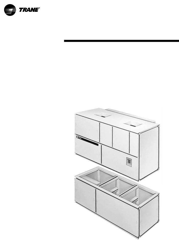
Commercial self contained units are complete HVAC systems used in floor-by- floor applications. Units are easy to install because they feature a single point power connection, factory installed and tested controls, single water point connection, factory installed options, and an internally trapped drain connection. Modular self-contained units can ship as split-apart units for installation ease. Splitapart units ship with a dry nitrogen charge and require field refrigerant charging.
Units consist of multiple compressors, water-cooled condensers (water-cooled units only), an evaporator coil, dual forward curved fans, and control panel. Air-cooled units require a remote aircooled condenser, model CXRC.The hermetically sealed 3-D scroll compressor motors utilize internal motor protection and time delays to prevent excessive cycling. Unit controls are either an electromechanical thermostat or microprocessor controls on the IntelliPak unit. See Figure I-GI-1 for a typical unit.
The hermetically sealed 3-D scroll compressor motors utilize internal motor protection and time delays to prevent excessive cycling.
The water-cooled condensers are shell and tube type with an internal subcooler. Condensers are available as mechani-
cally or chemically cleanable.The evaporator fan is double width, double inlet and forward curved with a fixed pitch belt drive assembly. Frequency drives or inlet guide vanes are optional. Motor options are standard efficiency open drip proof (ODP) or totally enclosed fan cooled (TEFC); or premium efficiency ODP.
All water-cooled units ship with a full refrigerant and oil charge. Air-cooled units ship with oil and a dry nitrogen holding charge and require field-piping refrigerant connections to the air cooled
condensing unit. Also, air-cooled units have two refrigerant circuits. Watercooled units have four refrigerant circuits; which include a filter drier, pressure relief valve, liquid line service valve, sight glass/ moisture indicator, thermal expansion valve with a sensing bulb and external equalizing line, discharge line shrader valve, a suction line shrader valve, and high and low pressure cutout switches. Water-cooled units also include a liquid line service valve for each circuit.
For more detailed information, see the Owner’s section of this manual.
Figure I-GI-1. IntelliPak® commercial self-contained Modular Series unit.
4 |
SCXG-SVX01B-EN |

General
Installation Information
Control Options
Units can have either a thermostat control or IntelliPak® UCM control network.
IntelliPak® Unit Controls
Standard controls supplied with the IntelliPak® unit include the human interface (HI) panel with unit control module (UCM), hi/lo inlet air temperature sensor, and frost protection. All setup parameters are preset from the factory.
Human Interface Panel
The HI is unit mounted and accessible without opening the unit’s front panel. It allows easy setpoint adjustment using the HI keypad. In addition, the HI displays all unit operating parameters and conditions in a clear language display, which can be configured for either English, French, or Spanish.
The optional remote human interface (RHI) will control up to four self-contained units, each containing an interprocessor communications bridge (IPCB). It has all the same features as the unit-mounted HI except for the service mode.
For more information on setpoint defaults and ranges and unit programming, see the IntelliPak® Self-Contained Programming Guide, PKG-SVP01B-EN. A copy ships with each unit.
Unit Control Module
The UCM provides “smart” unit control with safety features and control relays for pumps, dampers, etc. The Modular Series IntelliPak® self-contained unit is controlled by a microelectronic control system that consists of a network of modules.These modules are referred to
as unit control modules (UCM). In this manual, the acronym UCM refers to the entire control system network.
These modules perform specific unit functions using proportional/integral control algorithms. They are mounted in the unit control panel and are factory wired to their respective internal components. Each module receives and interprets information from other unit modules, sensors, remote panels, and customer binary contacts to satisfy the applicable request; i.e., economizing, mechanical cooling, heating, ventilation. See the Owner’s section of this manual for a detailed description of each module’s function.
Optional Controls
Optional controls include a disconnect switch, dirty filter switch, water flow switch (water-cooled only), supply air temperature reset, or external setpoint inputs. Night heat/morning warmup is available with electric, steam, or hot water heat control options.
The static pressure probe, zone night heat/morning warm up, supply air temperature reset sensor options ship separate inside the unit control panel for field installation. For more detailed information on the unit control options, see the Owner’s section of this manual.
Unit Nameplate
The unit nameplate identifies the unit model number, appropriate service literature, and wiring diagram numbers. It is mounted on the left end of the unit control panel.
SCXG-SVX01B-EN |
5 |

General
Installation Information
Model Number Description
Each self-contained unit has a multiple character model number unique to that unit.To determine a unit’s specific options, reference the model number on the unit nameplate using the model number explanation below.
S C W G N 20 4 |
2 BO A B 2 |
||||||
1 |
2 |
3 |
4 |
5 |
6 7 |
8 |
9 10 11 12 13 14 |
Digit 1 - Unit Model
S = Self Contained
Digit 2 - UnitType
C = Commercial
I = Industrial
Digit 3 - Condenser Medium
W = Water-Cooled
R = Remote Air-Cooled
Digit 4 - Development Sequence
G = Modular Series
Digit 5 - Refrigerant Circuit Configuration
N = Independent
Digit 6, 7 - Unit Nominal Capacity
20 = 20Tons (Water or Air Cooled)
25 = 25Tons (Water or Air Cooled)
30 = 30Tons (Water Cooled Only)
32 = 32Tons (Air Cooled Only)
35 = 35Tons (Water Cooled Only)
Digit 8 - UnitVoltage
6 = 200Volt/60 Hz/3 ph
4= 460 Volt/60 Hz/3 ph
5= 575 Volt/60 Hz/3 ph
Digit 9 - AirVolume/Temp Control
1= I-Pak & IGV and Supply AirTemp Ctrl
2= I-Pak &VFD and Supply Air Temp Ctrl
3= I-Pak &VFD w/ Bypass and Supply AirTemp Ctrl
4= I-Pak w/oVol. CTRL, w/ ZoneTemp Cool
5= I-Pak w/oVol. CTRL, w/ ZoneTemp Heat/Cool
6= I-Pak w/oVol. CTRL, w/ Supply Air Temp Ctrl
8= Thermostat Interface
9= Thermostat Interface w/Anti-Short
CycleTimer
A= Thermostat Interface w/ Compressor Start Delay
B= Thermostat Interface w/Anti-Short CycleTimer and Comp. Start Delay
Digit 10, 11 - Design Sequence
BO = “B” Design
Digit 12 - Unit Construction
A= Vertical Discharge
B= Vertical Discharge with DoubleWall
10 |
065 |
B |
A 1 0 1 0 A A |
C F A |
1 1 0 T 2 0 |
||
|
|
|
|
|
|
||
15 16 17 18 19 20 |
21 22 23 24 25 26 27 |
28 29 30 |
31 32 33 34 35 36 |
||||
C= Horizontal Discharge
D= Horizontal Discharge w/ Double Wall
E= Vertical Discharge, Ship Separate
F= Vertical Discharge w/ DoubleWall, Ship Separate
G= Horizontal Discharge, Ship Separate
H= Horizontal Discharge w/ Double Wall, Ship Separate
Digit 13 - PlenumType
B= Std Plenum w/ Factory Cut Holes
C= Low Plenum w/ Factory Cut Holes
E= Std Plenum w/ Field Cut Holes
F= Low Plenum w/ Field Cut Holes
H= Std Plenum DoubleWall (Perf) w/ Field Cut Holes
J= Low Plenum DoubleWall (Perf) w/ Field Cut Holes
L= Std. Plenum w/Factory Cut Holes, Ship Separate
M= Low Plenum with Factory Cut Holes, Ship Separate
P= Std Plenum w/ Field Cut Holes, Ship Separate
R= Low Plenum w/ Field Cut Holes, Ship Separate
U= Std Plenum DoubleWall (Perf) w/ Field Cut Holes, Ship Separate
V= Low Plenum DoubleWall (Perf) w/ Field Cut Holes, Ship Separate
0 = Without Plenum
Digit 14 - MotorType
1= Std. Efficiency ODP
2= Premium Eff. ODP
3= Std. EfficiencyTotally Enclosed
Digit 15, 16 - Motor HP
05 = 5 HP Motor
07 = 7.5 HP Motor
10 = 10 HP Motor
15 = 15 HP Motor
20 = 20 HP Motor
25 = 25 HP Motor
Digit 17, 18, 19 - Fan RPM
085 = 850 rpm
090 = 900 rpm
095 = 950 rpm
100 = 1000 rpm
105 = 1050 rpm
110 = 1100 rpm
115 = 1150 rpm
120 = 1200 rpm
125 = 1250 rpm
130 = 1300 rpm
135 = 1350 rpm
140 = 1400 rpm
145 = 1450 rpm
150 = 1500 rpm
155 = 1550 rpm
160 = 1600 rpm
165 = 1650 rpm
170 = 1700 rpm
175 = 1750 rpm
180 = 1800 rpm
185 = 1850 rpm
Digit 20 - HeatingType
A= Steam Coil, LH
B= Hot Water Coil, LH
C= Electric Heat, 1 Stage
F= Hydronic Heat Ctrl Interface
G= Elec. Heat Ctrl Interface, 1 stage
K= Steam Coil Ship Separate, LH
L= Hot Water Coil Ship Separate, LH
M= Steam Coil, RH
N= HotWater Coil, RH
P= Steam Coil Ship Separate, RH
R= Hot Water Coil Ship Separate, RH 0 = None
Digit 21 - Unit Isolators
A= Isopads
B= Spring Isolators 0 = None
Digit 22 - Unit Finish
1= Paint - Executive Beige
2= Protective Coating
3= Protective Coating w/ Finish Coat
Digit 23
0 = None
Digit 24 - Unit Connection
1= Disconnect Switch
2= Terminal Block
3= Dual Point Power
Digit 25 - Industrial Options
A= Protective Coated Evaporator Coil
B= Silver Solder
C= Stainless Steel Screws
D= A and B
E= A and C
6 |
SCXG-SVX01B-EN |

General
Installation Information
F= B and C
G= A, B and C 0 = None
Digit 26 - Drain PanType
A= Galvanized Sloped
B= Stainless Steel Sloped
Digit 27 - Waterside Economizer
A= Mechanical Clean Full Cap. (4-row)
B= Mechanical Clean Low Cap. (2-row)
C= Chemical Clean Full Cap. (4-row)
D= Chemical Clean Low Cap. (2-row)
E= Mechanical Clean Full Capacity
(4-row) Ship Separate
F= Mechanical Clean Low Capacity (2-row) Ship Separate
G= Chemical Clean Full Capacity (4-row) Ship Separate
H= Chemical Clean Low Capacity (2-row) Ship Separate
0 = None
Digit 28 - Ventilation Control
B= Airside Econ w/Traq™ Damper (Top O/A Inlet)
C= Airside Econ w/ Standard Dampers (Top O/A Inlet)
E= Airside Econ w/Traq™ Damper and Comparative Enthalpy
(Top O/A Inlet)
F= Airside Econ w/ Std Dampers and Comparative Enthalpy (Top O/A Inlet)
G= Traq Damper Ventilation Interface
H = Ventilation For 2 Pos. Cntrl Interface 0 = None
Digit 29 - Water Piping
A= Right Hand Condenser Connection
B= Left Hand Condenser Connection
C= Right Hand Basic Piping
D= Left Hand Basic Piping
E= Right Hand Intermediate Piping
F= Left Hand Intermediate Piping
J= Right Hand Basic w/ Flow Switch
K= Left Hand Basic w/ Flow Switch
L= Right Hand Intermediate
w/ Flow Switch
M = Left Hand Intermediate w/ Flow Switch
0 = None
Digit 30 - Condenser Tube Type
A= Standard Condenser Tubes
B= 90/10 CuNi CondenserTubes 0 = None
Digit 31 - Compressor Service Valves
1 = With Service Valves
0 = None
Digit 32 - Miscellaneous System Control
1= Timeclock
2= Interface for Remote HI
3= Dirty Filter Switch
4= 1 and 2
5= 1 and 3
6= 2 and 3
7= 1, 2, and 3
0 = None
Digit 33 - Control Interface Options
A = Generic BAS Module (GBAS)
B = Ventilation Override Module (VOM) C =Tracer Comm. Interface Module (TCI) D= Remote Human Interface (RHI)
E= GBAS and TCI
F= VOM and TCI
G = GBAS and VOM
H = GBAS and RHI
J = VOM and RHI
K = TCI and RHI
L = GBAS, VOM, and TCI
M = GBAS, VOM, and RHI N = GBAS, TCI, and RHI P = VOM, TCI, and RHI
R = GBAS, VOM, TCI, and RHI 0 = None
Digit 34 - Agency
T = UL Agency Listing
0 = None
Digit 35 - Filter Type
1= 2-inch Construction Throwaway
2= 2-inch Med Eff. Throwaway
Digit 36 - Miscellaneous Control Option
A= Low Entering AirTemp. Protect Device (LEATPD)
B= High Duct Temp T-Stat
C= Plenum High Static Switch
D= Kit for Heat Mode Output (w/t’stat)
E= A and B
F= A and C
G= B and C
H= A, B, and C
0 = None
Self-Contained Ship-With Accessory Model Number Description
P |
S |
W |
G |
S |
1 |
2 |
3 |
4 |
5 |
Digit 1 - Parts/Accessories
P = Parts/Accessories
Digit 2 - Unit Model
S= Self-Contained
Digit 3 - Shipment
W = With Unit
Digit 4 - Development Sequence
F = Signature Series
G = Modular Series
Digit 5 - Sensors and Other Accessories
S = Sensors
Digit 6 - Sensors and Thermostats (field installed)
A = BAYSENS017 - ZoneTemp Only (C V andVAV)
B = BAYSENS013 - ZoneTemp with Timed Override Button (CV andVAV)
A |
1 |
1 |
0 |
AO |
6 |
7 |
8 |
9 |
10 11 |
C = BAYSENS014 - ZoneTemp with Timed Override Button, Setpoint Dial (CV andVAV)
D = BAYSENS023 - Remote Min. Position Potentiometer Control (OA Damper)
E = BAYSENS008 - CV Zone Sensor
F = BAYSENS010 - CV Zone Sensor with Indicator Lights
G = BAYSENS019 - CV Programmable Night Setback Sensor
H = BAYSENS021 - VAV Zone Sensor with Indicator Lights
J = BAYSENS020 - VAV Programmable Night Setback Sensor
K = Remote Sensor Kit
L = Outside AirTemperature Sensor Kit M = Outside Air Humidity Sensor Kit
N = BAYSTAT010 - 2 Heat/2 Cool Thermostat
P = BAYSTAT037A - 2 Heat/2 Cool
Programmable Thermostat
0 = None
Digit 7 - Mixed Air Temperature Protection Kit (field installed)
1 = Mixed AirTemperature Protection Kit
0 = None
Digit 8 - Carbon Dioxide Sensor (field installed)
1 = Carbon Dioxide Sensor Kit
0 = None
Digit 9 - Future Option
0 = None
Digit 10, 11 - Design Sequence
A0 = A Design
SCXG-SVX01B-EN |
7 |

General
Installation Information
“After-Shipment” Accessory Model Number
S C W F |
N 20 |
4 |
2 AO A B 2 |
10 065 |
B |
A 1 0 1 0 A A |
C F |
A |
|
1 1 0 T 2 0 |
||||
1 |
2 |
3 |
4 |
5 |
6 7 |
8 |
9 10 11 12 13 14 |
15 16 17 18 19 20 |
21 22 23 24 25 26 27 |
28 29 |
30 |
31 32 33 34 35 36 |
||
Digit 1 - Parts/Accessories
P = Parts/Accessories
Digit 2 - Unit Model
S= Self-Contained
Digit 3 - Shipment
A = After Unit
Digit 4 - Development Sequence
F = Signature Series
G = Modular Series
Digit 5 - Condenser Medium
W = Water Cooled
R = Remote Air Cooled
Digit 6 - Refrigerant Circuit Configuration
N = Independent (Water-Cooled)
M = Manifolded (Air-Cooled)
Digits 7, 8 - Unit Nominal Capacity
20 = 20Tons (Water or Air)
22 = 22Tons (Water Only)
25 = 25Tons (Water or Air)
29 = 29Tons (Water or Air)
30 = 30Tons (Air Only)
32 = 32Tons (Water Only)
35 = 35Tons (Water or Air)
38 = 38Tons (Water Only)
40 = 40Tons (Air Only)
42 = 42Tons (Water Only)
46 = 46Tons (Water Only)
50 = 50Tons (Air Only)
52 = 52Tons (Water Only)
58 = 58Tons (Water Only)
60 = 60Tons (Air Only)
65 = 65Tons (Water Only)
72 = 72Tons (Water Only)
80 = 80Tons (Water Only)
Digit 9 - UnitVoltage
6 = 200 Volt/60 Hz/3 ph
4 = 460 Volt/60 Hz/3 ph
5 = 575 Volt/60 Hz/3 ph
0 = Not Defined
Digits 10, 11 - Design Sequence
A0 = A Design
Digit 12 - Unit Power Connection
1 = Single Point Power
2 = Dual Point Power
0 = Not Defined
Digit 13, 14 - Motor HP
05 = 5 HP Motor
07 = 7.5 HP Motor
10 = 10 HP Motor |
J = BAYSENS020 - VAV Programmable |
||
15 = 15 HP Motor |
Night Setback Sensor |
||
20 = 20 HP Motor |
K = Remote Sensor Kit |
||
25 = 25 HP Motor |
L = Outside AirTemperature Sensor Kit |
||
30 = 30 HP Motor |
M = Outside Air Humidity Sensor Kit |
||
40 = 40 HP Motor |
0 = None |
||
50 = 50 HP Motor (460V & 575V Only) |
Digit 22 - Low Entering Air Temperature |
||
0 |
= Not Defined |
||
Protection Device |
|||
|
|
||
Digit 15 - Exhaust/Comparative Enthalpy |
1 = Low Entering AirTemperature |
||
Module (Field Installed) |
Protection Device Kit |
||
1 |
= ECEM Kit |
0 = None |
|
2 |
= None |
Digit 23 - High Duct Temperature |
|
|
|
||
Digit 16 - Generic BAS Module |
Thermostat |
||
1 |
= GBAS 0-5 VDC Kit |
1 = High DuctTemp.Thermostat Kit |
|
0 |
= None |
0 = None |
|
Digit 17 - Heat Module |
Digit 24 - Plenum High Static Switch |
||
1 |
= Electric Heat Module Kit |
1 = Plenum High Static Switch Kit |
|
2 |
= Hydronic Heat Module Kit |
0 = None |
|
0 |
= None |
Digits 25 — 45 - Future Use |
|
|
|
||
Digit 18 - Remote Human Interface and |
0 = None |
||
IPCB |
|
||
1 |
= Remote Human Interface Panel Kit |
|
|
|
(RHI Only) |
|
|
2 |
= Interprocessor Communications |
|
|
|
Module Kit (IPCB Only) |
|
|
3 |
= RHI and IPCB Kit |
|
|
0 |
= None |
|
|
Digit 19 - Tracer Communications |
|
||
Interface Kit (TCI) |
|
||
1 |
= TCI Comm 3 Kit |
|
|
0 |
= None |
|
|
Digit 20 - Ventilation Override Module Kit |
|
||
(VOM) |
|
||
1 |
= VOM Kit |
|
|
0 |
= None |
|
|
Digit 21 - Sensors and Thermostats
A = BAYSENS017 - ZoneTemp Only (CV andVAV)
B = BAYSENS013 - ZoneTemp with Timed Override Button (CV andVAV)
C = BAYSENS014 - ZoneTemp with Timed Override Button, Setpoint Dial (CV andVAV)
E = BAYSENS008 - CV Zone Sensor
F = BAYSENS010 - CV Zone Sensor with Indicator Lights
G = BAYSENS019 - CV Programmable Night Setback Sensor
H = BAYSENS021 - VAV Zone Sensor with Indicator Lights
8 |
SCXG-SVX01B-EN |
Pre-Installation
Installation Considerations
Receiving and Handling
Shipping Package
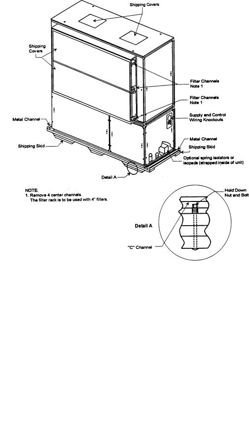
Commercial self-contained units ship assembled on skids with protective coverings over the coil and discharge openings. Figure I-PC-1 illustrates a typical shipping package.
Ship-Separate Accessories
Field-installed sensors ship separately inside the unit’s main control panel. Extra filters, sheaves, and belts ship in the unit’s fan motor section. Condenser plugs, spring isolators, and isopads ship in the unit’s bottom left side.
Receiving Checklist
Complete the following checklist immediately after receiving unit shipment to detect possible shipping damage.
οInspect individual cartons before accepting. Check for rattles, bent carton corners, or other visible indications of shipping damage.
οIf a unit appears damaged, inspect it immediately before accepting the shipment. Make specific notations concerning the damage on the freight bill. Do not refuse delivery.
οInspect the unit for concealed damage before it is stored and as soon as possible after delivery. Report concealed damage to the freight line within the allotted time after delivery. Check with the carrier for their allotted time to submit a claim.
οDo not move damaged material from the receiving location. It is the receiver’s responsibility to provide reasonable evidence that concealed damage did not occur after delivery.
οDo not continue unpacking the shipment if it appears damaged. Retain all internal packing, cartons, and crate. Take photos of damaged material if possible.
οNotify the carrier’s terminal of the damage immediately by phone and mail. Request an immediate joint inspection of the damage by the carrier and consignee.
οNotify yourTrane representative of the damage and arrange for repair. Have the carrier inspect the damage before making any repairs to the unit.
Figure I-PC-1. Typical unit mounted on shipping skid.
SCXG-SVX01B-EN |
9 |
Pre-Installation
Installation Considerations
Installation Preparation
Before installing the unit, perform the following procedures to ensure proper unit operation.
1.Verify the floor or foundation is level. Shim or repair as necessary.To ensure proper unit operation, install the unit level (zero tolerance) in both horizontal axis. Failure to level the unit properly can result in condensate management problems, such as standing water inside the unit. Standing water and wet surfaces inside units can result in microbial growth (mold) in the drain pan that may cause unpleasant odors and serious health-related indoor air quality problem.
2.Allow minimum recommended clearances for maintenance and routine service. See “Service Access” section on page 11.
3.Position the unit and skid assembly in its final location. If unit shipped splitapart, follow the procedure in the “Split-Apart Unit Assembly” section on page 14 before completing this step.Test lift the unit to determine exact unit balance and stability before hoisting it to the installation location. See Figure I-PC-7 and I-PC-8 on page 13 for typical rigging procedures, including cautions and proper uses of such equipment as fork lifts, spreader bars, and hooks.
4.Remove the skids from under the unit. See the “Rigging and Handling” section on page 12. Refer to the “Skid Removal” section on page 16. If you find internal damage, file a claim immediately to the delivering carrier.
5. Remove the protective shipping covers from the unit. Refer to the “Unit Protective Covers” section on page 39.
Note: Unit height and connection locations will change if external vibration isolators are used. The unit may be raised an additional 5 7/8 inches with spring-type isolators.
Note: Unit height and connection locations will change if the unit is constructed to be split-a-part in the field. See unit submittal drawings for connection locations.
6.Electrical supply power must meet specific balance and voltage requirements, as described in the “Electrical Requirements” section on page 37.
7.Water-cooled units only (model SXWG): The installer must furnish and install a condenser main and standby water pump, cooling tower, pressure gauges and all components for the waterside piping. See the “Water Piping” section on page 34 for general waterside recommendations.
8.Air-cooled units only (model SXRG): These units require field-installation of a remote air-cooled condenser and refrigerant piping. See the “Refrigerant Piping” section on page 36 for general piping recommendations.
10 |
SCXG-SVX01B-EN |
Pre-Installation
Installation Considerations
Service Access
See Figure I-PC-4 andTable I-PC-1 for recommended service and code clearances. Access to thermostat unit controls is through a hinged access panel door on the front, lower left of the unit’s compressor section.
IntelliPak® unit control access is through a panel on the middle right of the fan section. The panel is secured with an automatic latch and quick-acting fasteners, which require a screwdriver to open.
Removable front unit panels provide access to compressors, fan, motor, inlet guide-vane actuator, and belts.
Removable left side panels give access to drive side, fan bearing, inlet guide-vanes, condensers, and waterside economizer control valve.The compressor, con-
denser and fan motor access panels are secured with quick-acting fasteners. Access panels for evaporator coils, expansion and water valves, and left fan bearing are sheet metal screws. Access to other components for service requires removal of panels secured with sheet metal screws. During operation, sight glasses are viewable through portholes on the upper right side panel of the fan section.
! WARNING
Disconnect electrical power source before servicing the unit. Failure to do so may result in injury or death from electrical shock or entanglement in moving parts.
Table I-PC-1. SCWG/SIWG/SCRG/SIRG Clearance Requirements
Side |
Distance |
Purpose |
Front |
42 in. (1066 mm) |
NEC code requirement |
Left |
18 in. |
Air-cooled units only |
|
36 in. (914 mm) |
Refrigeration and waterside component service |
|
77 in. |
Fan shaft removal |
Right |
36 in. (914 mm) |
Provides uniform airflow |
Inlet |
18 in. (457 mm) |
Provides uniform airflow |
Air Inlet |
18” (457.2 mm) |
|
Minimum |
||
|
|
|
|
|
|
|
|
|
|
|
36” (914 mm) |
|
|
|
|
|
|
|
|
|
|
|
|
|
|
|
|
|
|
|
|
|
|
|
|
|
|
|
|
|
|
|
|
|
|
|
|
|
|
|
|
|
|
|
|
SeeTable |
|
|
|
|
|
|
|
|
||
|
|
|
|
|
|
|
|
Minimum |
||
|
|
|
|
|
|
|
|
|
|
|
|
|
|
|
|
|
|
|
|
|
|
|
|
|
|
|
|
|
|
|
|
|
|
|
|
|
|
|
|
|
|
|
|
42” (1066.8 mm) Minimum
Figure I-PC-4. Top view of self-contained unit showing recommended service and code clearances.
SCXG-SVX01B-EN |
11 |
Pre-Installation
Installation Considerations
Rigging and Unit Handling
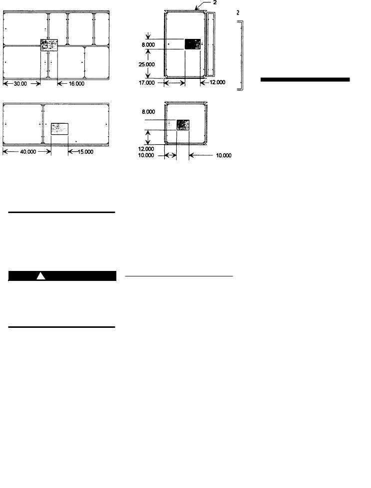
Before lifting the unit or modular component, determine the approximate center of gravity for lifting safety. See Figure I-PC-5 for assembled modular units and Figure I -PC-6 for split-apart units. The center of gravity may vary slightly within the gravity block depending on unit options.
! WARNING
Ensure lifting equipment capacity exceeds unit weight by an adequate safety factor to prevent injury, death, or unit damage.
Always test-lift the unit to determine the exact unit balance and stability before hoisting it to the installation location. See Figures I-PC-7 and I-PC-8 for typical rigging procedures and proper rigging equipment usage.
! WARNING
To prevent injury or death and unit damage, always test-lift the unit to determine actual center of gravity. See Figures I-PC-5 and I- PC-6.
Figure I-PC-5. Assembled unit gravity block location.
Table I-PC-2. Gravity Block Dimensions
Model |
A |
B |
C |
D |
SXWG |
36 |
14 |
38 |
12 |
SXRG |
36 |
16 |
40 |
12 |
Fan Section Only
Compressor Section Only
12 |
SCXG-SVX01B-EN |
Pre-Installation
Installation Considerations
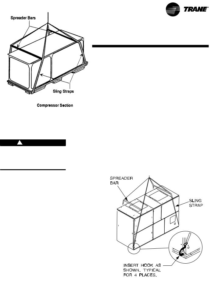
Rigging and Handling
Unit Shipping
1.Position rigging sling under wood shipping skid.
2.Use spreader bars to avoid unit damage.
3.When using a forklift, exercise caution to prevent unit damage.
4.Use the standard fork length to lift one end and drag or pull unit while skidding the opposite end.
5.The unit center of gravity will fall within center of gravity block at various locations depending on unit options.
6.Use hooks to lift fan section only. Do not hook into open channels to lift unit.
7.See unit nameplate for unit weight.
8.Do not stack units.
! CAUTION
Do not use hooks to lift unit or hook into open channels to lift unit. This could cause unit damage.
Figure I-PC-7. Assembled modular unit proper rigging.
Fan Section
Figure I-PC-8. Split-apart modular unit proper rigging.
SCXG-SVX01B-EN |
13 |

Pre-Installation
Installation Considerations
Split-Apart Unit Assembly
1.Ensure the tagging information on the fan section nameplate matches that on the compressor nameplate.
2.Remove the connector brackets holding the the sheet metal shipping cover on compressor section. Retain brackets and screws.
3.Remove shipping cover from the compressor section and verify the shipwith packge contains:
•suction and discharge line couplings
•insulation
•sheet metal screws
4.Lift fan section onto the compressor section using the rigging method in Figure I-PC-8 on page 13.
5.Remove skid from the fan section, placing the fan section onto the compressor section. Reference Figure I- PC-9 on page 15.
6.Install the connection brackets with the sheet metal screws (referenced in step 2) on all sides of the unit. Reference Detail “A” in Figure I-PC-9.
7.Remove the unit panels labeled RU and RL in Figure I-PC-10 on page 15.To remove panels, first remove the four shipping screws located in the corner of each panel. Next, turn the remaining 1/4 turn fasteners to the unlatch position. The panel is supported by a “lip” channel. So, lift the panel up and off the unit to remove it. See Detail “A”in Figure I-PC-9 on page 15.
8.Connect the drain hose to the drainpan outlet fitting and secure it with the drain hose clamp provided.
9.Circulate nitrogen thoughout refrigerant circuits.
10.Unbraze and remove the caps on the discharge and suction lines in both the compressor and fan sections.
11.Install and braze discharge and suction line couplings.
12.Insulate discharge and suction lines with the insulation provided.
13. Remove panel FLR and open the bottom control panel door, FLL. Pull the fan motor leads (coiled in the fan section) through the knockout in the bottom of the fan section to the control panel. Ensure that the bushing is installed in the hole to prevent the wires from chafing. Refer to the unit wiring diagrams to connect the fan motor leads properly and ensure correct phase sequencing.
IntelliPak Units (UCM) Only
14.Remove panels FML, FMM, and FMR.
15.Pull the circular plug connector (CPC) from the compressor section through the knockouts into the fan section. Install the bushings (provided on the wiring harnesses) in the knockouts.
16.Using the CPC wiring diagram, connect the male CPC to the female CPC in the top control panel.
17.If the unit has the mixed air temperature option, route the capillary tube on back of the filter rack.
Units withThermostat Only
18.Remove panel FMR. See Note 1 on Figure I-PC-10.
19.Pull frost protection wires from the bottom control panel throughknockouts in bottom of fan section. Route wires to the appropriate frost protection switches on the evaporator coil. Reference the unit wiring diagrams to connect frost protection wiring connectors.
Air-Cooled Units Only:
20. Route the refrigerant circuit wires for circuits 1 and 2 from the bottom control panel through the knockouts to the solenoid valves.The solenoid valves are located in the liquid refrigerant lines on the right-hand side of the unit. Refer to the unit wiring diagrams to make splice connections.
14 |
SCXG-SVX01B-EN |

Pre-Installation
Installation Considerations
Figure I-PC-9 How to assemble the split apart modular unit.
Figure I-PC-10 Modular unit panel description and internal connections.
SCXG-SVX01B-EN |
15 |
Pre-Installation
Installation Considerations
Skid Removal
The unit ships on skids to provide forklift locations from the front or rear.The skid allows easy maneuverability of the unit during storage and transportation.
Remove the skids before placing the unit in its permanent location.
Remove the skids using a forklift or jack. Lift one end of the unit off of the skids. See Figure I-PC-5 and I-PC-6 on page 12 for unit gravity block location. Slide the skids out and lower the unit at the installation location.
Note: External isolation is not necessary since units are internally isolated. Consult a vibration specialist before “doubleisolating” the unit.
External Unit Isolation
If your job requires external vibration isolation, two options are available: isopads or spring-type isolators. Isopads should be placed under the unit at locations indicated on the factoryprovided isolator sheet.
Set the spring-type isolators (Figure I-PC- 9) in position after the unit is removed from skids before making electrical, piping, or duct connections. All units require a minimum of four isolators per unit. But some may require six isolators, depending upon unit options. Note: The Trane Company strongly recommends you consult a vibration specialist before double-isolating the unit. Double isolation is not recommended.
If you decide to externally isolate the unit, use spring-flex, type CP isolators. The spring number is marked on the outer housing. See Figure I-PC-9.
To install external isolators, complete the following procedure.
1.Locate the isolators under unit base at the locations indicated on the factoryprovided isolator placement sheet. Lift one end of the unit at a time to position isolators to the floor, using anchor bolts.
2.Level the unit by adjusting isolator heights. Unit weight may cause the upper housing to rest on the lower housing of the spring isolators. The isolator clearance shown in the side view of Figure I-PC-9, must be 1/4 - 1/2 inches.To increase the clearance, lift
Figure I-PC-9. Optional spring isolator dimensional data.
the unit off the isolator and turn the leveling bolt counterclockwise. Recheck the unit level and the housing clearances. Maximum allowable difference between isolator heights is 1/4 inch. Shim as required under the isolators.
Note: The compressors and fan assembly are internally isolated on most units. Due to this, the addition of external isolation devices (spring mounting isolators) is at the discretion of the building or HVAC system designer.
Pre-Installation Checklist
Complete the following checklist before beginning unit installation.
οVerify the unit size and tagging with the unit nameplate.
οMake certain the floor or foundation is level, solid, and sufficient to support the unit and accessory weights. SeeTable I-DW-1 on page 32. Level or repair the floor before positioning the unit if necessary.
οAllow minimum recommended clearances for routine maintenance and service. Refer to unit submittals for dimensions.
οAllow three fan diameters above the unit for the discharge ductwork. Return air enters the rear of the unit and
conditioned supply air discharges through the top.
οElectrical connection knockouts are on the top, left side of the unit.
οAllow adequate space for piping access and panel removal. Condenser water piping, refrigerant piping, and condensate drain connections are on the lower left end panel.
Note: Unit height and connection locations will change if using vibration isolators. The unit height may increase up to 5 7/8” with spring type isolators.
οElectrical supply power must meet specific balance and voltage requirements as described in the “Electrical Requirements” section on page 37.
οWater-cooled units only: The installer is responsible for providing a condenser main, standby water pump, cooling tower, pressure gauges, strainers, and all components for waterside piping. See the “Water Piping” section on page 34 for general waterside recommendations.
οAir-cooled units only: The installer is responsible for providing and installing the remote air-cooled condenser and refrigerant piping, including filter driers.
16 |
SCXG-SVX01B-EN |
Installation |
Dimensions |
and Weights |
|
|
|
|
|
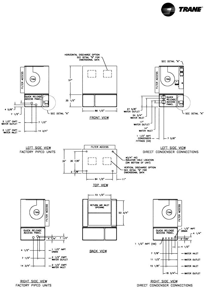
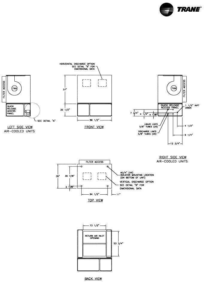
SCWG/SIWG Unit —
English - (inches)
ON PAGE 21 |
ON PAGE 20 |
|
ON PAGE 21 |
ON PAGE 21 |
ON PAGE 21
SCXG-SVX01B-EN |
17 |
Installation |
Dimensions |
and Weights |
|
|
|
|
|
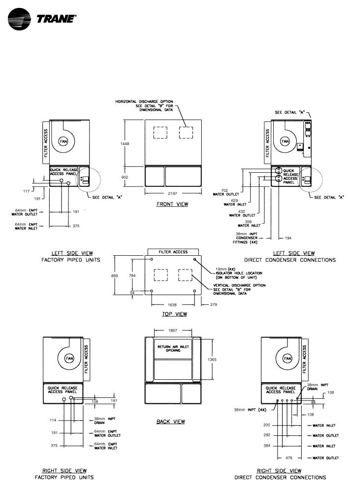
SCWG/SIWG Unit —
Metric- (mm)
ON PAGE 21 |
ON PAGE 21 |
|
ON PAGE 21 |
ON PAGE 21 |
ON PAGE 21
18 |
SCXG-SVX01B-EN |
Installation |
Dimensions |
and Weights |
|
|
|
|
|
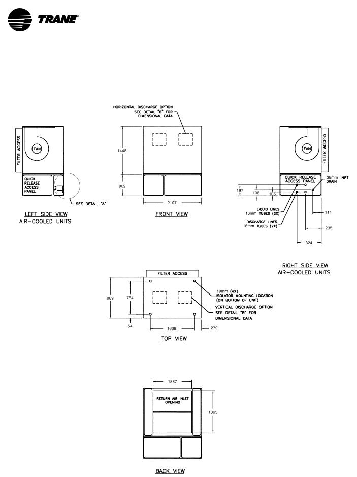
SCRG/SIRG Unit —
English - (inches)
ON PAGE 21
ON PAGE 21
ON PAGE 21
SCXG-SVX01B-EN |
19 |
|
Dimensions |
Installation |
and Weights |
|
|
|
|
SCRG/SIRG Unit —
Metric - (mm)
ON PAGE 21
ON PAGE 21
ON PAGE 21
20 |
SCXG-SVX01B-EN |
|
|
Dimensions |
Installation |
and Weights |
|
|
|
|
|
|
|
SCRG/SIRG/SCWG/SIWG Detail |
SCRG/SIRG/SCWG/SIWG Detail |
“A” Electrical Connections — |
“A” Electrical Connections — |
English - (inches) |
Metric - (mm) |
Detail “B” Discharge Options — English - (inches) and Metric (mm)
Unit Dimensions - English, (inches)
UnitTons |
A |
B |
C |
D |
E |
F |
SCWG/SCRG 20 |
20 |
10 3/4 |
58 1/2 |
5 1/8 |
13 1/4 |
11 1/2 |
SCWG/SCRG 25 |
19 1/4 |
12 1/4 |
57 5/8 |
5 1/8 |
13 1/4 |
11 1/2 |
SCWG 30 - 35/SCRG 32 |
18 |
14 5/8 |
56 1/2 |
5 1/8 |
13 1/4 |
11 1/2 |
Unit Dimensions - Metric (mm)
UnitTons |
A |
B |
C |
D |
E |
F |
SCWG/SCRG 20 |
508 |
508 |
1486 |
130 |
337 |
292 |
SCWG/SCRG 25 |
489 |
489 |
1464 |
130 |
337 |
292 |
SCWG 30 - 35/SCRG 32 |
457 |
457 |
1435 |
130 |
337 |
292 |
SCXG-SVX01B-EN |
21 |
|
Dimensions |
Installation |
and Weights |
|
|
|
|
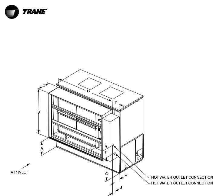
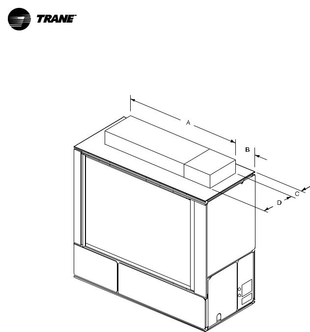
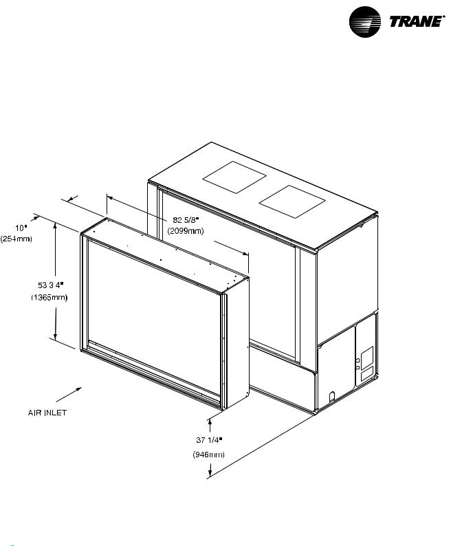
Hot Water Coil
Hot Water Coil Dimensions - English - (inches)
UnitTon |
A |
B |
C |
D |
E |
F |
G |
H |
J |
20 - 35 |
37 1/4 |
53 3/4 |
16 5/8 |
73 1/2 |
14 7/8 |
16 1/4 |
43 1/4 |
5 5/8 |
73/4 |
Hot Water Coil Dimensions - Metric (mm)
UnitTon |
A |
B |
C |
D |
E |
F |
G |
H |
J |
20 - 35 |
946 |
1365 |
422 |
1867 |
378 |
413 |
1099 |
143 |
187 |
22 |
SCXG-SVX01B-EN |
Installation |
Dimensions |
and Weights |
|
|
|
|
|
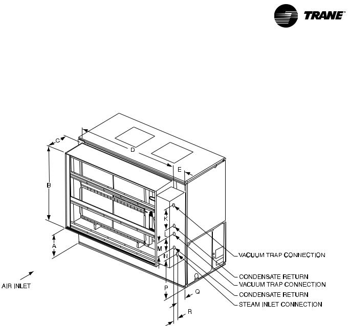
Steam Coil
Steam Coil Dimensions - English - (inches)
UnitTon |
A |
B |
C |
D |
E |
K |
L |
M |
N |
P |
Q |
R |
20 - 35 |
37 1/4 |
53 3/4 |
16 5/8 |
73 1/2 |
10 7/8 |
22 1/2 |
3 3/8 |
15 7/8 |
1 |
41 |
9 3/8 |
4 3/8 |
Steam Coil Dimensions - Metric (mm)
UnitTon |
A |
B |
C |
D |
E |
K |
L |
M |
N |
P |
Q |
R |
20 - 35 |
946 |
1365 |
422 |
1867 |
276 |
572 |
86 |
403 |
25 |
1041 |
238 |
111 |
SCXG-SVX01B-EN |
23 |
|
Dimensions |
Installation |
and Weights |
|
|
|
|
Electric Heat Coil
24 |
SCXG-SVX01B-EN |
|
Dimensions |
Installation |
and Weights |
|
|
|
|
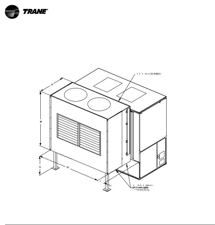
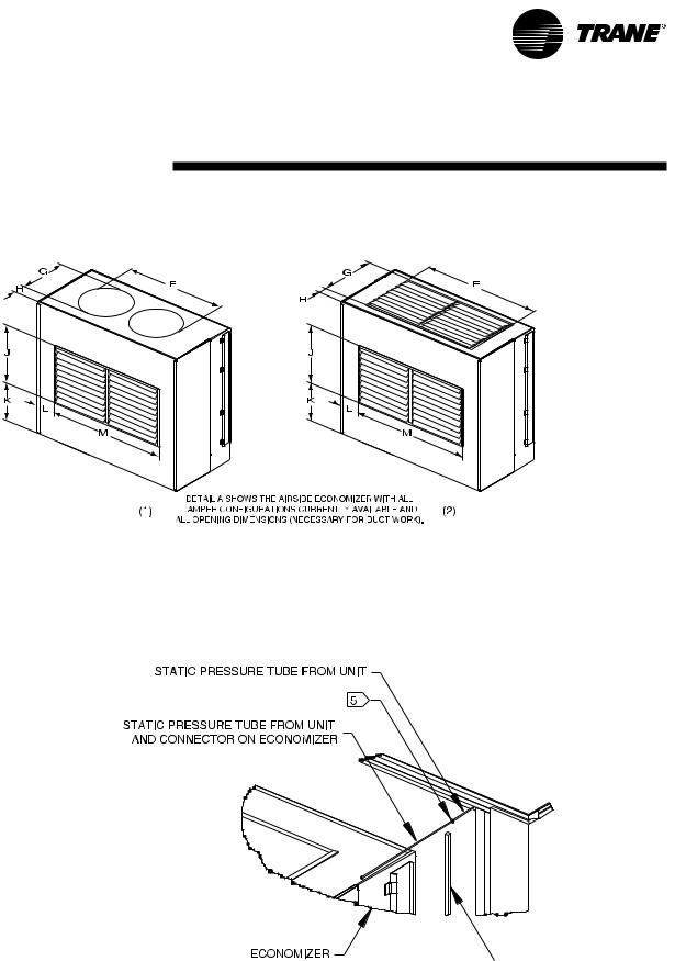
Waterside Economizer
SCXG-SVX01B-EN |
25 |
Installation |
|
|
|
Dimensions |
|
|
|
and Weights |
|
|
|
|
|
|
|
|
|
|
|
|
|
|
|
|
Airside Economizer Dimensions - English - (inches)
|
Unit Size |
A |
B |
|
C |
D |
|
E |
|
F (1) |
F (2) |
G (1) |
G (2) |
H (1) |
H (2) |
J |
|
K |
|
L |
|
M |
|
|
SCWG/SIWG 20, 25 |
36 |
65 5/8 |
37 |
74 1/4 |
6 1/8 |
56 1/2 |
49 3/4 |
23 1/4 |
20 1/2 |
5 5/8 |
7 |
20 1/2 |
17 1/8 |
17 |
49 3/4 |
|||||||
SCRG/SIRG 20 |
|
|
|
|
|
|
|
|
|
|
|
|
|
|
|
|
|
|
|
|
|
|
|
SCWG/SIWG 30, 35 |
36 |
65 |
5/ |
37 |
74 |
1/ |
6 |
1/ |
61 3/ |
62 3/ |
28 1/ |
20 1/ |
3 1/ |
7 |
20 |
1/ |
17 |
1/ |
5 |
1/ |
62 |
3/ |
|
|
|
|
|
8 |
|
|
4 |
|
8 |
8 |
4 |
8 |
2 |
4 |
|
|
2 |
|
8 |
|
2 |
|
4 |
SCRG/SIRG 25, 32
Airside Economizer Dimensions - Metric (mm)
|
Unit Size |
A |
B |
C |
D |
E |
F (1) |
F (2) |
G (1) |
G (2) |
H (1) |
H (2) |
J |
K |
L |
M |
|
SCWG/SIWG 20, 25 |
914 |
1667 |
940 |
1886 |
156 |
1435 |
1264 |
591 |
521 |
143 |
178 |
521 |
435 |
305 |
1264 |
SCRG/SIRG 20 |
|
|
|
|
|
|
|
|
|
|
|
|
|
|
|
|
SCWG/SIWG 30, 35 |
914 |
1667 |
940 |
1886 |
156 |
1559 |
1594 |
714 |
521 |
83 |
178 |
521 |
435 |
140 |
1594 |
|
SCRG/SIRG 25, 32 |
|
|
|
|
|
|
|
|
|
|
|
|
|
|
|
|
26 |
SCXG-SVX01B-EN |
Dimensions
and Weights
Detail “A”
Detail “B”


 (Factory provided for field installation)
SCXG-SVX01B-EN |
27 |
Installation |
Dimensions |
and Weights |
|
|
|
|
|
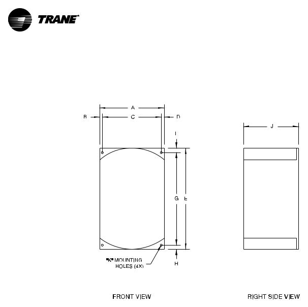
Variable Frequency Drive
Variable Frequency Drive Dimensions - English - (inches)
MotorHP |
Voltage |
A |
|
B |
C |
|
D |
E |
|
F |
|
G |
|
H |
J |
|
|
K |
Weight |
||||
7.5 |
200V |
9 |
|
1/ |
2 |
8 |
|
1/ |
2 |
12 |
3/ |
1/ |
4 |
12 |
1/ |
1/ |
4 |
8 |
1/ |
1/ |
4 |
26 lbs. |
|
|
|
|
|
|
|
|
|
|
4 |
|
|
4 |
|
|
|
4 |
|
|
|||||
7.5 |
460V |
6 |
7/ |
3/ |
8 |
6 |
1/ |
3/ |
8 |
11 |
1/ |
3/ |
8 |
10 |
1/ |
3/ |
8 |
7 |
1/ |
1/ |
4 |
15 lbs. |
|
|
|
|
8 |
|
|
8 |
|
|
4 |
|
|
2 |
|
|
|
4 |
|
|
|||||
10 |
200V |
9 |
|
1/ |
2 |
8 |
|
1/ |
2 |
12 |
3/ |
1/ |
4 |
12 |
1/ |
1/ |
4 |
8 |
1/ |
1/ |
4 |
26 lbs. |
|
|
|
|
|
|
|
|
|
|
4 |
|
|
4 |
|
|
|
4 |
|
|
|||||
10 |
460V |
9 |
|
1/ |
2 |
8 |
|
1/ |
2 |
12 |
3/ |
1/ |
4 |
12 |
1/ |
1/ |
4 |
8 |
1/ |
1/ |
4 |
26 lbs. |
|
|
|
|
|
|
|
|
|
|
4 |
|
|
4 |
|
|
|
4 |
|
|
|||||
15 |
200V |
9 |
5/ |
3/ |
4 |
8 |
1/ |
3/ |
4 |
22 |
|
3/ |
8 |
21 |
1/ |
3/ |
8 |
11 |
1/ |
1/ |
4 |
75 lbs. |
|
|
|
|
8 |
|
|
8 |
|
|
|
|
|
4 |
|
|
|
4 |
|
|
|||||
15 |
460V |
9 |
|
1/ |
2 |
8 |
|
1/ |
2 |
12 |
3/ |
1/ |
4 |
12 |
1/ |
1/ |
4 |
8 |
1/ |
1/ |
4 |
26 lbs. |
|
|
|
|
|
|
|
|
|
|
4 |
|
|
4 |
|
|
|
4 |
|
|
|||||
20 |
200V |
9 |
5/ |
3/ |
4 |
8 |
1/ |
3/ |
4 |
22 |
|
3/ |
8 |
21 |
1/ |
3/ |
8 |
11 |
1/ |
1/ |
4 |
75 lbs. |
|
|
|
|
8 |
|
|
8 |
|
|
|
|
|
4 |
|
|
|
4 |
|
|
|||||
20 |
460V |
9 |
|
1/ |
2 |
8 |
|
1/ |
2 |
16 |
3/ |
1/ |
4 |
15 |
7/ |
1/ |
4 |
8 |
1/ |
1/ |
4 |
31 lbs. |
|
|
|
|
|
|
|
|
|
|
8 |
|
|
8 |
|
|
|
4 |
|
|
|||||
25 |
200V |
14 |
1 |
|
12 |
1 |
|
26 |
|
3/ |
8 |
24 |
3/ |
7/ |
8 |
12 |
1/ |
3/ |
8 |
126 lbs. |
|||
|
|
|
|
|
|
|
|
|
|
|
|
|
|
4 |
|
|
|
8 |
|
|
|||
25 |
460V |
9 |
5/ |
3/ |
4 |
8 |
1/ |
3/ |
4 |
22 |
|
3/ |
8 |
21 |
1/ |
3/ |
8 |
11 |
1/ |
1/ |
4 |
75 lbs. |
|
|
|
|
8 |
|
|
8 |
|
|
|
|
|
4 |
|
|
|
4 |
|
|
|||||
Variable Frequency Drive Dimensions - Metric (mm)
MotorHP |
Voltage |
A |
B |
C |
D |
E |
F |
G |
H |
J |
K |
Weight |
7.5 |
200V |
229 |
13 |
203 |
13 |
324 |
6 |
311 |
6 |
210 |
6 |
12 kg. |
7.5 |
460V |
175 |
10 |
156 |
10 |
286 |
10 |
267 |
10 |
184 |
6 |
7 kg. |
10 |
200V |
229 |
13 |
203 |
13 |
324 |
6 |
311 |
6 |
210 |
6 |
12 kg. |
10 |
460V |
229 |
13 |
203 |
13 |
324 |
6 |
311 |
6 |
210 |
6 |
12 kg. |
|
|
|
|
|
|
|
|
|
|
|
|
|
15 |
200V |
244 |
19 |
206 |
19 |
559 |
10 |
540 |
10 |
286 |
6 |
34 kg. |
15 |
460V |
229 |
13 |
203 |
13 |
324 |
6 |
311 |
6 |
210 |
6 |
12 kg. |
20 |
200V |
244 |
19 |
206 |
19 |
559 |
10 |
540 |
10 |
286 |
6 |
34 kg. |
20 |
460V |
229 |
13 |
203 |
13 |
416 |
6 |
403 |
6 |
210 |
6 |
14 kg. |
25 |
200V |
356 |
25 |
305 |
25 |
660 |
10 |
629 |
22 |
308 |
10 |
57 kg. |
25 |
460V |
244 |
19 |
206 |
19 |
559 |
10 |
540 |
10 |
10 |
286 |
34 kg. |
28 |
SCXG-SVX01B-EN |
|
Dimensions |
Installation |
and Weights |
|
|
|
|
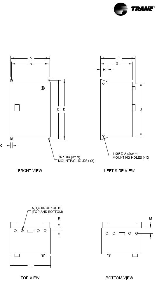
Variable Frequency
Drive with Bypass
SCXG-SVX01B-EN |
29 |

|
Dimensions |
Installation |
and Weights |
|
|
|
|
Variable Frequency Drive With Bypass Dimensions - English - (inches)
MotorHP |
Voltage |
A |
|
B |
|
C |
|
D |
E |
|
F |
|
G |
|
H |
|
J |
|
K |
|
L |
|
M |
Weight |
|
7.5 |
200V |
19 |
1/ |
17 |
1/ |
1 |
7/ |
41 |
39 |
3/ |
13 |
1/ |
12 |
|
3 |
1/ |
38 |
|
1 |
1/ |
20 |
1/ |
2 |
3/ |
126 lbs. |
|
|
|
2 |
|
2 |
|
8 |
|
|
4 |
|
2 |
|
|
|
4 |
|
|
|
4 |
|
2 |
|
8 |
|
7.5 |
460V |
14 |
1/ |
12 |
1/ |
1 |
7/ |
35 |
33 |
3/ |
13 |
1/ |
12 |
|
3 |
1/ |
32 |
|
1 |
1/ |
14 |
3/ |
2 |
3/ |
87 lbs. |
|
|
|
2 |
|
4 |
|
8 |
|
|
4 |
|
2 |
|
|
|
4 |
|
|
|
4 |
|
4 |
|
8 |
|
10 |
200V |
19 |
1/ |
17 |
1/ |
1 |
7/ |
41 |
39 |
3/ |
13 |
1/ |
12 |
|
3 |
1/ |
38 |
|
1 |
1/ |
20 |
1/ |
2 |
3/ |
126 lbs. |
|
|
|
2 |
|
2 |
|
8 |
|
|
4 |
|
2 |
|
|
|
4 |
|
|
|
4 |
|
2 |
|
8 |
|
10 |
460V |
19 |
1/ |
17 |
1/ |
1 |
7/ |
41 |
39 |
3/ |
13 |
1/ |
12 |
|
3 |
1/ |
38 |
|
1 |
1/ |
20 |
1/ |
2 |
3/ |
126 lbs. |
|
|
|
2 |
|
2 |
|
8 |
|
|
4 |
|
2 |
|
|
|
4 |
|
|
|
4 |
|
2 |
|
8 |
|
15 |
200V |
20 |
|
18 |
|
1 |
7/ |
49 |
47 |
7/ |
16 |
3/ |
14 |
7/ |
6 |
|
46 |
3/ |
-- |
|
20 |
1/ |
-- |
|
180 lbs. |
|
|
|
|
|
|
|
8 |
|
|
8 |
|
8 |
|
8 |
|
|
|
8 |
|
|
|
2 |
|
|
|
15 |
460V |
19 |
1/ |
17 |
1/ |
1 |
7/ |
41 |
39 |
3/ |
13 |
1/ |
12 |
|
3 |
1/ |
38 |
|
1 |
1/ |
20 |
1/ |
2 |
3/ |
126 lbs. |
|
|
|
2 |
|
2 |
|
8 |
|
|
4 |
|
2 |
|
|
|
4 |
|
|
|
4 |
|
2 |
|
8 |
|
20 |
200V |
20 |
|
18 |
|
1 |
7/ |
49 |
47 |
7/ |
16 |
3/ |
14 |
7/ |
6 |
|
46 |
3/ |
-- |
|
20 |
1/ |
-- |
|
180 lbs. |
|
|
|
|
|
|
|
8 |
|
|
8 |
|
8 |
|
8 |
|
|
|
8 |
|
|
|
2 |
|
|
|
20 |
460V |
19 |
1/ |
17 |
1/ |
1 |
7/ |
41 |
39 |
3/ |
13 |
1/ |
12 |
|
3 |
1/ |
38 |
|
1 |
1/ |
20 |
1/ |
2 |
3/ |
126 lbs. |
|
|
|
2 |
|
2 |
|
8 |
|
|
4 |
|
2 |
|
|
|
4 |
|
|
|
4 |
|
2 |
|
8 |
|
25 |
200V |
20 |
|
18 |
|
1 |
7/ |
49 |
47 |
7/ |
16 |
3/ |
14 |
7/ |
6 |
|
46 |
3/ |
-- |
|
20 |
1/ |
-- |
|
180 lbs. |
|
|
|
|
|
|
|
8 |
|
|
8 |
|
8 |
|
8 |
|
|
|
8 |
|
|
|
2 |
|
|
|
25 |
460V |
20 |
|
18 |
|
1 |
7/ |
49 |
47 |
7/ |
16 |
3/ |
14 |
7/ |
6 |
|
46 |
3/ |
-- |
|
20 |
1/ |
-- |
|
180 lbs. |
|
|
|
|
|
|
|
8 |
|
|
8 |
|
8 |
|
8 |
|
|
|
8 |
|
|
|
2 |
|
|
|
Variable Frequency Drive With Bypass Dimensions - Metric (mm)
MotorHP |
Voltage |
A |
B |
C |
D |
E |
F |
G |
H |
J |
K |
L |
M |
Weight |
7.5 |
200V |
495 |
445 |
48 |
1041 |
1010 |
343 |
305 |
83 |
965 |
38 |
521 |
60 |
57 kg. |
7.5 |
460V |
362 |
311 |
48 |
889 |
857 |
343 |
305 |
83 |
813 |
38 |
375 |
60 |
40 kg. |
10 |
200V |
495 |
445 |
48 |
1041 |
1010 |
343 |
305 |
83 |
965 |
38 |
521 |
60 |
57 kg. |
10 |
460V |
495 |
445 |
48 |
1041 |
1010 |
343 |
305 |
83 |
965 |
38 |
521 |
60 |
57 kg. |
15 |
200V |
508 |
457 |
48 |
1244 |
1216 |
416 |
378 |
152 |
1178 |
-- |
521 |
-- |
82 kg. |
15 |
460V |
495 |
445 |
48 |
1041 |
1010 |
343 |
305 |
83 |
965 |
38 |
521 |
60 |
57 kg. |
20 |
200V |
508 |
457 |
48 |
1244 |
1216 |
416 |
378 |
152 |
1178 |
-- |
521 |
-- |
82 kg. |
20 |
460V |
495 |
445 |
48 |
1041 |
1010 |
343 |
305 |
83 |
965 |
38 |
521 |
60 |
57 kg. |
25 |
200V |
508 |
457 |
48 |
1244 |
1216 |
416 |
378 |
152 |
1178 |
-- |
521 |
-- |
82 kg. |
25 |
460V |
508 |
457 |
48 |
1244 |
1216 |
416 |
378 |
152 |
1178 |
-- |
521 |
-- |
82 kg. |
30 |
SCXG-SVX01B-EN |
 Loading...