


 Loading...
Installation
Owner
Diagnostics
AxiomTM Horizontal/Vertical
Water-Source Comfort System
Models GEH and GEV
15 - 25 Ton
1/2 - 5 Ton
6 - 10 Ton
6 - 15 Ton
Models
“A” and later Design Sequence
GEH |
GEV |
006 - 060 – 60 HZ |
006 - 060 – 60 HZ |
006 - 060 – 50 HZ |
006 - 060 – 50 HZ |
072 - 180 – 60 HZ |
072 - 300 – 60 HZ |
072 - 150 – 50 HZ |
072 - 240 – 50 HZ |
WSHP-SVX01D-EN
Notice
NOTICE:
Warnings and Cautions appear at appropriate sections throughout this manual. Read these carefully.
WARNING -Indicates a potentially hazardous situation which, if not avoided, could result in death or serious injury.
CAUTION -Indicates a potentially hazardous situation which, if
not
avoided, may result in minor or moderate injury. It may also be used to alert against unsafe practices.
CAUTION -Indicates a situation that may result in equipment or property-damage-only accidents.
Important!
Equipment is shipped FOB (Free on Board) at the manufacturer. Therefore, freight claims for damages against the carrier must be initiated by the receiver.
NOTICE:
Unit contains HCFC (R-22) Refrigerant Instructions!
Section 608, Paragraph C of the 1990 Clean Air Act states:
Effective July 1, 1992, it shall be unlawful for any person, in course of maintaining, servicing, repairing, or disposing of an air conditioning system, to knowingly vent or release any CFC or HCFC refrigerant. Minimal releases (air purges or refrigerant hoses) associated with good faith attempts to recapture or recycle are exempt from the ban on venting.
© 2004 American Standard Inc. All rights reserved. |
WSHP-SVX01D-EN |

Contents
Installation/Startup/Commissioning |
4 |
|
|
Pre-installation Checklist |
4 |
|
|
|
|
General Information |
5 |
|
|
|
|
Dimensions/Weights |
7 |
|
|
|
|
Installation Instructions |
48 |
|
|
|
|
Electrical Requirements |
67 |
|
|
|
|
Pre-Startup Checklist |
73 |
|
|
|
|
Startup/Commissioning |
74 |
|
|
|
|
Sequence of Operation |
74 |
|
|
|
|
|
|
Startup Checklist & Log |
81 |
|
|
Maintenance |
|
|
|
82 |
|
|
|
|
|
Warranty Information |
83 |
|
|
|
|
Troubleshooting Checklist |
84 |
|
|
|
|
Unit Wiring |
86 |
|
|
WSHP-SVX01D-EN |
3 |

Pre-installation
Checklist
 WARNING Fiberglass Wool!
Product contains fiberglass wool. Disturbing the insulation in this product during installation, maintenance or repair will expose you to airborne particles of glass wool fibers and ceramic fibers known to the state of California to cause cancer through inhalation. Glass wool fibers may also cause respiratory, skin or eye irritation.
Jobsite Inspection
Always perform the following checks before accepting a unit:
1.Verify that the nameplate data matches the data on the sales order and bill of lading (including electrical data).
2.Verify that the power supply complies with the unit nameplate specifications.
3.Visually inspect the exterior of the unit, for signs of shipping damage. Do not sign the bill of lading accepting the unit(s) until inspection has been completed. Check for damage promptly after the unit(s) are unloaded. Once the bill of lading is signed at the jobsite, the unit(s) are now the property of the SOLD TO party and future freight claims MAY NOT be accepted by the freight company.
4.Verify that the refrigerant charge has been retained during shipment by use of gauges. Schrader taps are located internal to the cabinet.
5.After assuring that charge has been retained, reinstall the schrader caps to assure that refrigerant leakage does not occur.
 WARNING Microbial Growth!
Wet interior unit insulation can become an amplification site for microbial growth (mold), which may cause odors and serious health related indoor air quality problems. If there is evidence of microbial growth (mold) on the interior insulation, remove or replace the insulation prior to operating the system. Failure to remove microbial growth could result in serious health problems.
Jobsite Storage
This unit is intended for indoor use only. To protect the unit from damage due to the elements, and to prevent possible IAQ contaminant sources from growing, the unit should be stored indoors. If indoor storage is not possible, the following provisions for outdoor storage must be met:
1.Place the unit(s) on a dry surface or raise above the ground to assure adequate air circulation beneath the unit.
2.Cover the unit(s) with a water proof tarp to protect them from the elements.
3.Make provisions for continuous venting of the covered units to prevent moisture from standing on the unit(s) surfaces. Wet interior unit insulation can become an amplification site for microbial growth (mold) which has been determined to be a cause of odors and serious health related indoor air quality problems.
4.Store units in the normal UP orientation to maintain oil in the compressor.
5.Horizontal units may be stacked no more than three units high. Do not stack the vertical unit configurations.
4 |
WSHP-SVX01D-EN |

General
Information
Unit Nameplate
The unit nameplate is located on the outside of the control box access panel at the front of the unit. It includes the unit model number, serial number, electrical characteristics, refrigerant charge, and other pertinent unit data.
Compressor Nameplate
The nameplate for the compressors are located on the compressor shell.
Unit Description
Before shipment, each unit is leak tested, dehydrated, charged with refrigerant and run tested for proper control operation.
Air-to-Refrigerant Coil
The air-to-refrigerant coil is aluminum fin, mechanically bonded to the copper tubing.
Water-to-Refrigerant Coil
The water-to-refrigerant coil is a copper or cupro-nickel (option) and steel tube (tube-within-a-tube) design, leak tested to assure there is no cross leakage between the water tube (copper/ cupro-nickel) and refrigerant gas (steel tube).
Controls
The control system offered to control the unit is a Basic 24 Volt control for the 1/2 through 5 ton sizes, a Deluxe 24 Volt control option for all unit sizes, a TracerTM ZN510, LonTalkTM certified control option for the 1/2 through 5 ton unit sizes, or a Tracer ZN524, LonTalk certified control option for all unit sizes.
All power wiring to the equipment is made at the unit contactor for the 1/2 through 5 ton, and at the high voltage terminal block for the 6 through 25 ton. All low voltage wiring is made at the unit’s low voltage terminal board.
System Input Devices and Functions
A thermostat, zone sensor or building automation system is required to operate the water-source heat pump. The flexibility of having several mode ca-
pabilities depends upon the type of sensor and/or remote panel selected. Troubleshooting and connection diagrams for the 24 Volt control systems may be located in the back of this manual. All digital control troubleshooting tips and connection diagrams are located in WSHP-IOP-2 (ZN510) or WSHP-PRB002-EN (ZN524).
Basic 24V Controls
Safety devices for equipment containing the basic 24V control option include a low pressure switch or suction line temperature sensor to prevent compressor operation during low temperature activity. The switch or sensor is set to activate at refrigerant pressures of 20 psig (1/2 to 5 ton units) or 7 psig (6 to 25 ton units) to fit most applications.
A high pressure switch prevents compressor operation during high or excessive discharge pressures exceeding 395 psig.
The lockout relay communicates the low or high pressure situation to the compressor to prevent operation. For units that contain a condensate overflow switch option, a condensate overflow situation will also be communicated to the compressor through the lockout relay if an overflow condition exists. The relay may be reset at the thermostat, or by cycling power to the unit.
General alarm is accomplished through the lockout relay and is used in driving light emitting diodes (LEDs). This feature will drive dry contacts only, and cannot be used to drive field installed control inputs.
(option) Deluxe 24V Controls
Units containing the Deluxe 24V control design will incorporate a micro- processor-based control board. The Trane microprocessor board is factory wired to a terminal strip to provide all necessary terminals for field connection. The deluxe board is equipped with a random start relay, anti-short cycle timer, brown out protection,
compressor disable, condensate overflow, unit safety control, diagnostics and a generic relay (which may be available for field use). See page 56 for diagnostic information and thermostat connections.
(option) Tracer ZN510 or ZN524
Controls
The digital ZN510 and ZN524 controller is designed to support the 1/2 through 25 ton water-source heat pumps in either a standalone, peer-to- peer with a Tracer Loop Controller, or as a full building automation (open protocal) system. The 1/2 through 5 ton units that incorporate direct digital controls will typically come equipped with the ZN510 control board. The exception to this would be if the equipment contained hot gas reheat, waterside economizer, or boilerless control with electric heat. The ZN524 digital control board is designed to interface and run these mechanical options. All units over 5 tons would ship with the Tracer ZN524 control board.
For installation, operation and diagnostics of the ZN510 and ZN524 WSHP-IOP-2 (ZN510) and/or WSHP- PRB002-EN (ZN524).
(option) Waterside Economizer
Instructions for mechanical connection of the waterside economizer to the water-source heat pump may be found in the dimensional section of this manual.
The waterside economizer is designed to begin economizing mode when water temperatures fall below the field adjustable temperature of 25, 35, 45, 55 or 65 F (for the Deluxe control option), or below the programmed setpoint (for the ZN524 control option).
When the temperature is less than the setpoint, fluid will flow into the economizing coil, while simultaneously halting mechanical operation of the compressor. Mechanical cooling will continue on a call for a second stage from the thermostat or system control.
WSHP-SVX01D-EN |
5 |

General
Information
(option) Boilerless Control/Electric
Heat
Systems that do not contain a boiler may contain a boilerless control with electric heat. Trane offers both a factory mounted electric heat option, and a field mounted duct heater option.
If the 1/2 through 5 ton GEH and GEV unit incorporates the factory mounted option, the unit will ship from the factory with an internally mounted nichrome open wire heating element, designed to start-up electric heat as the systems primary heat in the event entering water temperature falls below 55 F. Once the entering water temperature rises above 60 F, the boilerless controller returns the unit to normal compressor heating operation, and locks out the electric heater.
If the unit contains a cooling only heat pump design, the electric heat contactor is wired directly to the thermostat for primary heating, and the compressor contactor for cooling.
For units comprised of the field installed duct heater option, the unit will ship from the factory with controls available to interface with the field provided electric heat selection.
Note: For geothermal applications, the boilerless controller has an adjustable setting of 25, 35, 45, 55 and 60 degrees.
(option) Supplemental or
Boilerless Electric Heat
The 6 through 25 ton models which contain boilerless control electric heat or supplemental electric heat will contain the controls interface ONLY for field provided electric heat selection. The heater for this model shall be external to the equipment by the contractor for ease of installation. All power connections for the electric heater will be completely separate from the unit for field supplied electric heat.
Note: When the unit has boilerless control, the electric heat is not used as supplemental electric heat, but as a primary heat.
(option) Hot Gas Reheat
With the reheat option, the return-air from the space is conditioned by the air-to-refrigerant coil, then reheated by the reheat coil to control not only the space temperature, but to also reduce the relative humidity of the space. When operating in the reheat mode (meaning the sensible temperature has been met in the space), the humidistat signals the reheat relay coil to energize, allowing the high pressure refrigerant gas to flow from the compressor through the reheat valve, into the reversing valve, or reheat coil for dehumidification.
A switching relay has been provided for the reheat application to adjust the blower motor from normal operation to low speed when the hot gas reheat is energized (for 1/2 through 5 ton equipment only).
Notes:
• A high static blower motor is required to support the hot gas reheat option for the 1/2 through 5 ton equipment.
•Units containing the hot gas reheat option should not be used as a make-up air unit.
•Water regulating valves should not be used with the hot gas reheat option. Trane places a thermal expansion valve on all WSHPs as well as GSHPs to regulate refrigerant flow vs. water flow to the unit.
6 |
WSHP-SVX01D-EN |

Dimensions/Weights
Table 1: Unit weights
GEH |
GEH |
GEV |
GEV |
Shipping Weight |
Shipping Weight |
60 HZ |
50 HZ |
60 HZ |
50 HZ |
with pallet |
w/o pallet |
|
|
|
|
|
|
006-015 |
006-012 |
|
|
188 lb (85 kg) |
158 lb (71 kg) |
|
|
|
|
|
|
018-030 |
015-024 |
|
|
278 lb (125 kg) |
248 lb (112 kg) |
036-042 |
030-036 |
|
|
318 lb (143 kg) |
288 lb (130 kg) |
|
|
|
|
|
|
048-060 |
042-060 |
|
|
428 lb (193 kg) |
398 lb (179 kg) |
|
|
|
|
|
|
072 |
- |
|
|
701 lb (318 kg) |
652 lb (296 kg) |
|
|
|
|
|
|
090 |
072 |
|
|
714 lb (325 kg) |
666 lb (303 kg) |
|
|
|
|
|
|
120 |
090 |
|
|
831 lb (377 kg) |
789 lb (359 kg) |
|
|
|
|
|
|
150 |
120 |
|
|
907 lb (412 kg) |
865 lb (393 kg) |
180 |
150 |
|
|
999 lb (454 kg) |
957 lb (435 kg) |
|
|
006-015 |
006-012 |
178 lb (80 kg) |
158 lb (71 kg) |
|
|
|
|
|
|
|
|
018-030, 040 |
015-024 |
268 lb (121 kg) |
248 lb (112 kg) |
|
|
036, 042 |
030, 036 |
308 lb (139 kg) |
288 lb (130 kg) |
|
|
|
|
|
|
|
|
048, 060 |
042-060 |
396 lb (178 kg) |
248 lb (112 kg) |
|
|
|
|
|
|
|
|
|
|
|
Operating Weight |
|
|
|
|
|
|
|
|
072 |
- |
617 lb (280 kg) |
577 (262 kg) |
|
|
|
|
|
|
|
|
090 |
072 |
648 (294 kg) |
608 (276 kg) |
|
|
|
|
|
|
|
|
120 |
090 |
861 (391 kg) |
821 (373 kg) |
|
|
150 |
120 |
1215 lb (547 kg) |
1170 lb (527 kg) |
|
|
|
|
|
|
|
|
180 |
150 |
1225 lb (551 kg) |
1180 lb (531 kg) |
|
|
|
|
|
|
|
|
240 |
180 |
1615 lb (727 kg) |
1580 lb (711 kg) |
|
|
|
|
|
|
|
|
300 |
240 |
1665 lb (749 kg) |
1640 lb (738 kg) |
|
|
|
|
|
|
Table 2: Waterside economizer weight
GEV |
GEV |
Economizer |
|
GEH |
GEH |
Economizer |
60 HZ |
50 HZ |
Weight |
|
60 HZ |
50 HZ |
Weight |
|
|
|
|
|
|
|
072 |
- |
148 lb (67 kg) |
|
006-015 |
006-012 |
54 lb (24.5 kg) |
|
|
|
|
|
|
|
090 |
072 |
168 lb (76 kg) |
|
018-030 |
015-024 |
65 lb (29.5 kg) |
120 |
090 |
207 lb (94 kg) |
|
036-042 |
030-036 |
76 lb (35 kg) |
|
|
|
|
|
|
|
150, 180 |
120, 150 |
275 lb (125 kg) |
|
048-060 |
042-060 |
97 lb (44 kg) |
|
|
|
|
|
|
|
240 |
180 |
310 lb (141 kg) |
|
|
|
|
|
|
|
|
|
|
|
300 |
240 |
395 lb (179 kg) |
|
|
|
|
|
|
|
|
|
|
|
 WARNING Improper Unit Lift!
Test lift unit approximately 24 inches to verify proper center of gravity lift point. To avoid dropping of unit, reposition lifting point if unit is not level. Failure to properly lift unit could result in death or serious injury or possible equipment or property-only damage.
GEH |
GEH |
Economizer |
60 HZ |
50 HZ |
Weight |
|
|
|
072 |
- |
138 lb (63 kg) |
|
|
|
090 |
072 |
144 lb (65 kg) |
120 |
090 |
166 lb (75 kg) |
|
|
|
150 |
120 |
213 lb (97 kg) |
|
|
|
180 |
150 |
213 lb (97 kg) |
|
|
|
Weight Distribution for Hanging the GEH Model
•Approximate weight distribution for proper hanging of the GEH unit is indicated by the diagram to the right.
•Tolerance on the weights deter-
mined are ± 15%. |
1/2 through 5-ton |
6 through 15-ton |
•Total weights for each unit size are listed above.
WSHP-SVX01D-EN |
7 |
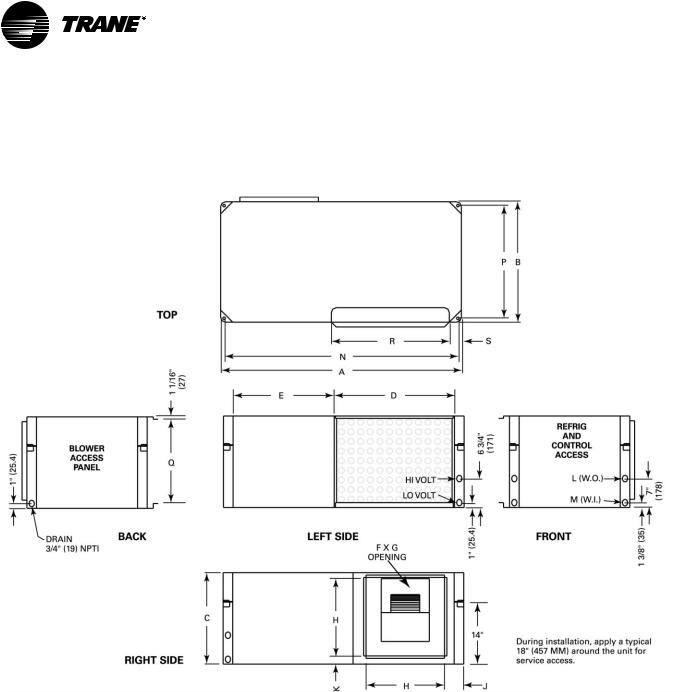
Dimensions/Weights
Clearance
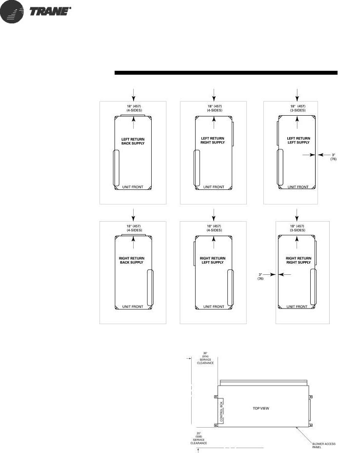
GEH Clearance Dimensions
Access to the unit for service purposes should be provided at installation. All 1/2 through 5 ton configurations require an 18" (457 mm) surround clearance from other mechanical and electrical equipment (where shown) to enable panel removal from the unit for service/maintenance ability. Some local codes require a greater service clearance than listed below. Check all code requirements prior to unit installations.
Equipment containing a same-side supply/return combination requires a 3" (229 mm) limitation on one side. Access to the TXV may not be possible with this 3" (229 mm) clearance. This configuration is typically applied in a corridor installation, where space limitations force the left or right side of the unit against a wall.
Service clearance dimensions for the 6 through 15 ton horizontal includes a two side access appropriate for control and blower motor/ wheel access. Some local codes require a greater service clearance than listed below. Check all code requirements prior to unit installations.
GEH 1/2 through 5 Ton Clearance
GEH 6 through 15 Ton Clearance
8 |
WSHP-SVX01D-EN |
Dimensions/Weights
Clearance
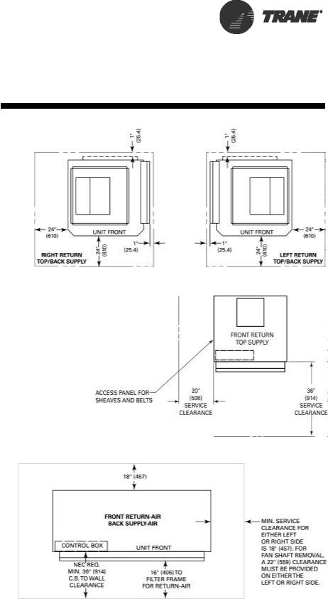
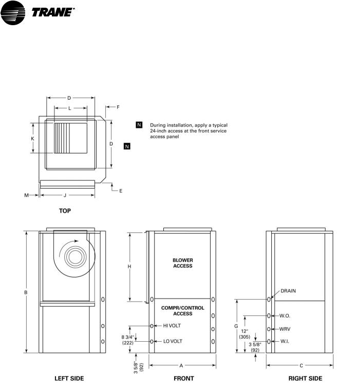
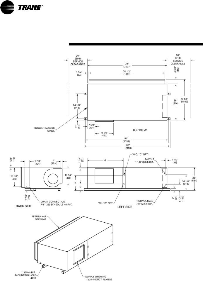
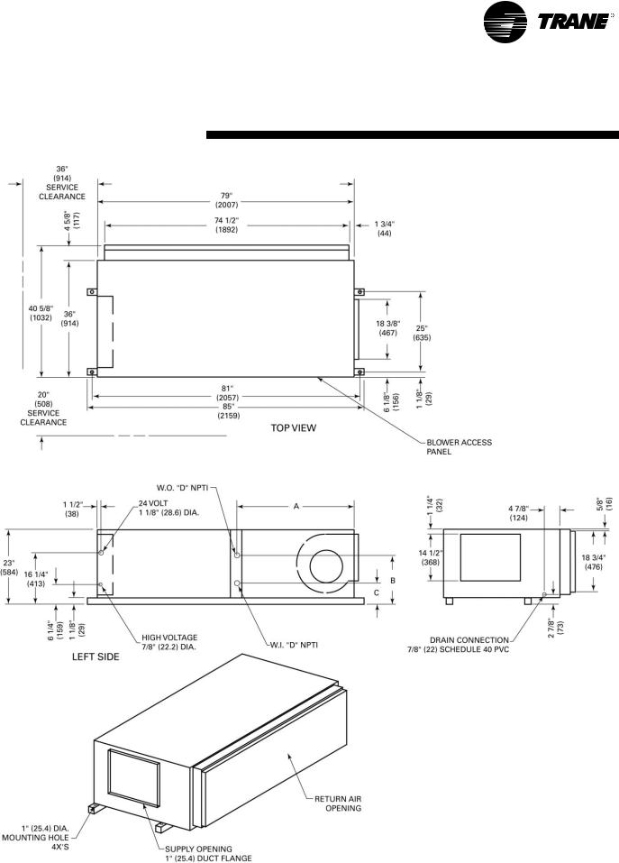
GEV 1/2 through 5 Ton Clearance Dimensions (Figure 1)
Access to the unit for service purposes should be provided at installation. All configurations require an 24" (610 mm) surround clearance from other mechanical and electrical equipment (where shown) to enable panel removal from the unit for service/maintenance ability. Some local codes require a greater service clearance than listed below. Check all code requirements prior to unit installations. Units in afree return application will require more than a 1" (25.4) clearance to provide proper air flow to the units air-to-refrig- erant coil.
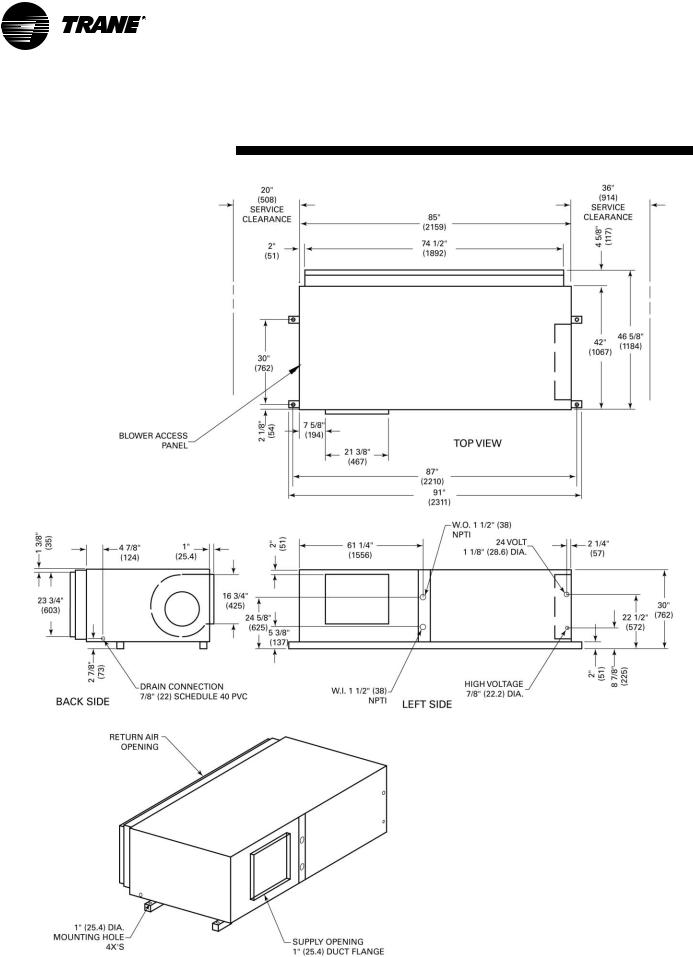
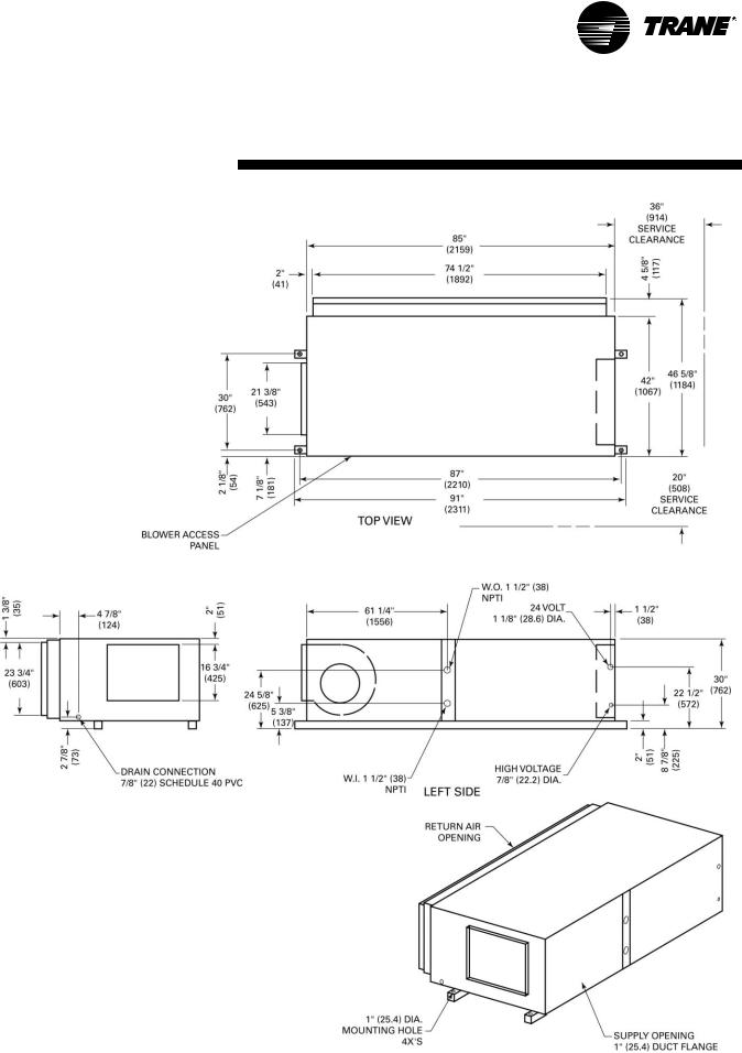
GEV 6 through 10 Ton Clearance Dimensions (Figure 2)
Minimum access for service clearances are provided below. Any one unit side other than the control panel or returnair side may be placed against a wall. The unit may be serviced through the three remaining open sides. Some local codes require a greater service clearance than listed below. Check all code requirements prior to unit installations.
GEV 12 1/2 through 25 Ton Clearance Dimensions (Figure 3)
The diagram below outlines the minimum required unit service clearances. Any one unit side other than the control panel or return-air side may be placed against a wall. The unit may be serviced through the three remaining open sides. Some local codes require a greater service clearance than listed below. Check all code requirements prior to unit installations.
Figure 1: GEV 1/2 through 5 Ton Clearance
Figure 2: GEV 6 through 10 Ton Clearance
Figure 3: GEV 12 1/2 through 25 Ton Clearance
WSHP-SVX01D-EN |
9 |
Dimensions/Weights
Left Return/Left Supply
|
|
|
|
|
|
|
|
|
|
|
|
|
|
|
|
|
|
|
|
|
|
|
|
|
|
|
|
|
|
|
|
|
|
|
|
|
|
|
|
|
|
Unit |
A |
B |
C |
D |
E |
F |
G |
H |
|
J |
|
K |
L |
M |
N |
P |
Q |
R |
S |
|
|
|
NPTI |
NPTI |
|
||||||||||||||||
|
|
|
|
|
|
|
|
|
|
|
|
|
|
|
|
|
|
|
||
006,009 |
40" |
20" |
15" |
20" |
15" |
6 7/8" |
8" |
11 1/2" |
4 |
1/4" |
2 |
1/8" |
1/2" |
1/2" |
38 3/4" |
18 3/4" |
13 5/8" |
18 1/2" |
3 3/8" |
|
(1016) |
(508) |
(381) |
(508) |
(381) |
(175) |
(203) |
(292) |
(108) |
(54) |
(12.7) |
(12.7) |
(984) |
(476) |
(346) |
(470) |
(86) |
|
|||
012, 015 |
40" |
20" |
15" |
20" |
15" |
6 7/8" |
9 7/8" |
11 1/2" |
4 |
1/4" |
2 |
5/8" |
1/2" |
1/2" |
38 3/4" |
18 3/4" |
13 5/8" |
18 1/2" |
3 3/8" |
|
(1016) |
(508) |
(381) |
(508) |
(381) |
(175) |
(251) |
(292) |
(108) |
(67) |
(12.7) |
(12.7) |
(984) |
(476) |
(346) |
(470) |
(86) |
|
|||
018 |
46" |
23" |
17" |
23" |
18" |
8 1/4" |
9 3/4" |
13 1/2" |
4 |
3/4" |
2 |
7/8" |
3/4" |
3/4" |
44 3/4" |
21 3/4" |
15 5/8" |
18 1/2" |
4 1/4" |
|
(1168) |
(584) |
(432) |
(584) |
(457) |
(210) |
(248) |
(343) |
(121) |
(73) |
(19) |
(19) |
(1137) |
(552) |
(397) |
(470) |
(108) |
|
|||
|
|
|||||||||||||||||||
024, 030 |
46" |
23" |
17" |
23" |
18" |
8 1/4" |
11 3/8" |
13 1/2" |
4 |
3/4" |
2 |
7/8" |
3/4" |
3/4" |
44 3/4" |
21 3/4" |
15 5/8" |
18 1/2" |
4 1/4" |
|
(1168) |
(584) |
(432) |
(584) |
(457) |
(210) |
(289) |
(343) |
(121) |
(73) |
(19) |
(19) |
(1137) |
(552) |
(397) |
(470) |
(108) |
|
|||
036, 042 |
50" |
25" |
19" |
25" |
20" |
10 1/2" |
13 1/2" |
16 3/8" |
|
4" |
1 |
3/4" |
3/4" |
3/4" |
48 3/4" |
23 3/4" |
17 5/8" |
23 1/2" |
3 1/4" |
|
(1270) |
(635) |
(483) |
(635) |
(508) |
(267) |
(343) |
(416) |
(102) |
(45) |
(19) |
(19) |
(1238) |
(603) |
(448) |
(597) |
(83) |
|
|||
048, 060 |
58" |
33" |
21" |
25" |
28" |
13 7/8" |
13 7/8" |
18" |
6 |
5/8" |
|
2" |
1" |
1" |
56 3/4" |
31 3/4" |
19 5/8" |
23 1/2" |
5 1/2" |
|
(1473) |
(838) |
(533) |
(635) |
(711) |
(352) |
(352) |
(457) |
(168) |
(51) |
(25.4) |
(25.4) |
(1441) |
(806) |
(498) |
(597) |
(140) |
|
|||
10 |
WSHP-SVX01D-EN |
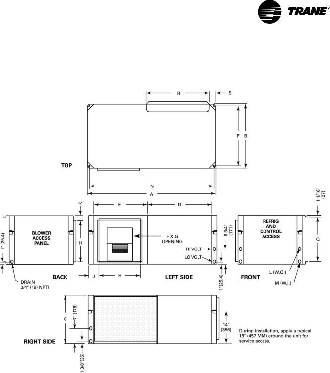
Dimensions/Weights
Left Return/Back Supply
|
|
|
|
|
|
|
|
|
|
|
|
|
|
|
|
|
|
|
|
|
|
|
|
|
|
|
|
|
|
|
|
|
|
|
|
|
|
|
|
|
|
Unit |
A |
B |
C |
D |
E |
F |
G |
H |
|
J |
|
K |
L |
M |
N |
P |
Q |
R |
S |
|
|
|
NPTI |
NPTI |
|
||||||||||||||||
|
|
|
|
|
|
|
|
|
|
|
|
|
|
|
|
|
|
|
||
006,009 |
40" |
20" |
15" |
20" |
15" |
6 7/8" |
8" |
11 1/2" |
4 |
1/4" |
2 |
1/8" |
1/2" |
1/2" |
38 3/4" |
18 3/4" |
13 5/8" |
18 1/2" |
3 3/8" |
|
(1016) |
(508) |
(381) |
(508) |
(381) |
(175) |
(203) |
(292) |
(108) |
(54) |
(12.7) |
(12.7) |
(984) |
(476) |
(346) |
(470) |
(86) |
|
|||
012, 015 |
40" |
20" |
15" |
20" |
15" |
6 7/8" |
9 7/8" |
11 1/2" |
4 |
1/4" |
2 |
5/8" |
1/2" |
1/2" |
38 3/4" |
18 3/4" |
13 5/8" |
18 1/2" |
3 3/8" |
|
(1016) |
(508) |
(381) |
(508) |
(381) |
(175) |
(251) |
(292) |
(108) |
(67) |
(12.7) |
(12.7) |
(984) |
(476) |
(346) |
(470) |
(86) |
|
|||
018 |
46" |
23" |
17" |
23" |
18" |
8 1/4" |
9 3/4" |
13 1/2" |
4 |
3/4" |
2 |
7/8" |
3/4" |
3/4" |
44 3/4" |
21 3/4" |
15 5/8" |
18 1/2" |
4 1/4" |
|
(1168) |
(584) |
(432) |
(584) |
(457) |
(210) |
(248) |
(343) |
(121) |
(73) |
(19) |
(19) |
(1137) |
(552) |
(397) |
(470) |
(108) |
|
|||
|
|
|||||||||||||||||||
024, 030 |
46" |
23" |
17" |
23" |
18" |
8 1/4" |
11 3/8" |
13 1/2" |
4 |
3/4" |
2 |
7/8" |
3/4" |
3/4" |
44 3/4" |
21 3/4" |
15 5/8" |
18 1/2" |
4 1/4" |
|
(1168) |
(584) |
(432) |
(584) |
(457) |
(210) |
(289) |
(343) |
(121) |
(73) |
(19) |
(19) |
(1137) |
(552) |
(397) |
(470) |
(108) |
|
|||
036, 042 |
50" |
25" |
19" |
25" |
20" |
10 1/2" |
13 1/2" |
16 3/8" |
|
4" |
1 |
3/4" |
3/4" |
3/4" |
48 3/4" |
23 3/4" |
17 5/8" |
23 1/2" |
3 1/4" |
|
(1270) |
(635) |
(483) |
(635) |
(508) |
(267) |
(343) |
(416) |
(102) |
(45) |
(19) |
(19) |
(1238) |
(603) |
(448) |
(597) |
(83) |
|
|||
048, 060 |
58" |
33" |
21" |
25" |
28" |
13 7/8" |
13 7/8" |
18" |
6 |
5/8" |
|
2" |
1" |
1" |
56 3/4" |
31 3/4" |
19 5/8" |
23 1/2" |
5 1/2" |
|
(1473) |
(838) |
(533) |
(635) |
(711) |
(352) |
(352) |
(457) |
(168) |
(51) |
(25.4) |
(25.4) |
(1441) |
(806) |
(498) |
(597) |
(140) |
|
|||
WSHP-SVX01D-EN |
11 |
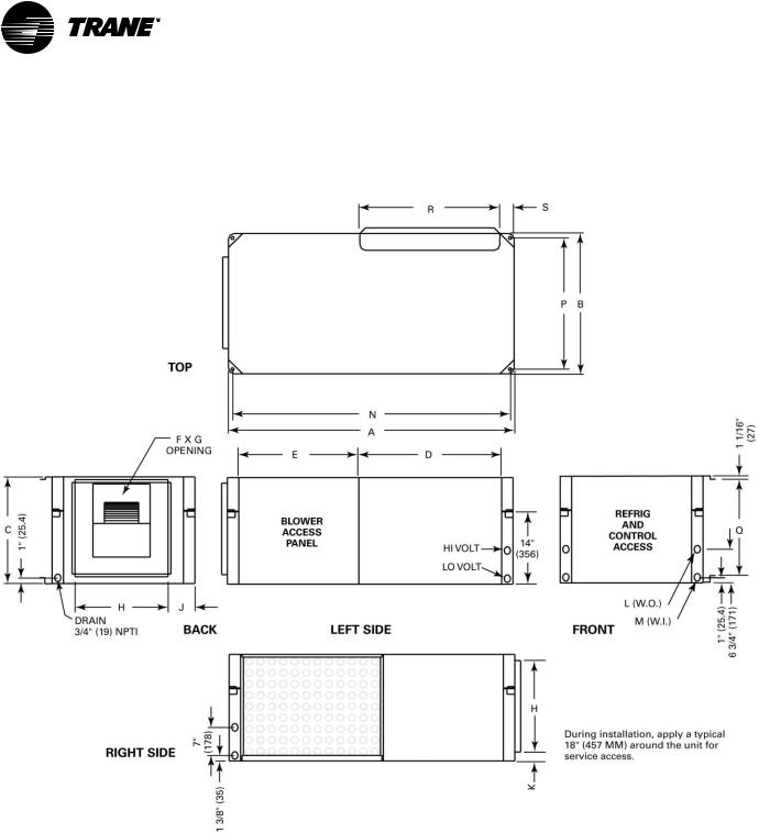
Dimensions/Weights
Left Return/Right Supply
|
|
|
|
|
|
|
|
|
|
|
|
|
|
|
|
|
|
|
|
|
|
|
|
|
|
|
|
|
|
|
|
|
|
|
|
|
|
|
|
|
|
Unit |
Unit |
A |
B |
C |
D |
|
E |
F |
G |
H |
|
J |
|
K |
L |
M |
N |
P |
Q |
R |
60 HZ |
50 HZ |
|
|
|
NPTI |
NPTI |
||||||||||||||
|
|
|
|
|
|
|
|
|
|
|
|
|
|
|
|
|
||||
006-009 |
006 |
40" |
20" |
15" |
20" |
|
15" |
6 7/8" |
8" |
11 1/2" |
4 |
1/4" |
2 |
1/8" |
1/2" |
1/2" |
38 3/4" |
18 3/4" |
13 5/8" |
18 1/2" |
(1016) |
(508) |
(381) |
(508) |
|
(381) |
(175) |
(203) |
(292) |
(108) |
(54) |
(12.7) |
(12.7) |
(984) |
(476) |
(346) |
(470) |
||||
|
|
|
||||||||||||||||||
012-015 |
009-012 |
40" |
20" |
15" |
20" |
|
15" |
6 7/8" |
9 7/8" |
11 1/2" |
4 |
1/4" |
2 |
5/8" |
1/2" |
1/2" |
38 3/4" |
18 3/4" |
13 5/8" |
18 1/2" |
(1016) |
(508) |
(381) |
(508) |
|
(381) |
(175) |
(251) |
(292) |
(108) |
(67) |
(12.7) |
(12.7) |
(984) |
(476) |
(346) |
(470) |
||||
018 |
015 |
46" |
23" |
17" |
23" |
|
18" |
8 1/4" |
9 3/4" |
13 1/2" |
4 |
3/4" |
2 |
7/8" |
3/4" |
3/4" |
44 3/4" |
21 3/4" |
15 5/8" |
18 1/2" |
(1168) |
(584) |
(432) |
(584) |
|
(457) |
(210) |
(248) |
(343) |
(121) |
(73) |
(19) |
(19) |
(1137) |
(552) |
(397) |
(470) |
||||
|
|
|
||||||||||||||||||
024-030 |
018-024 |
46" |
23" |
17" |
23" |
|
18" |
8 1/4" |
11 3/8" |
13 1/2" |
4 |
3/4" |
2 |
7/8" |
3/4" |
3/4" |
44 3/4" |
21 3/4" |
15 5/8" |
18 1/2" |
(1168) |
(584) |
(432) |
(584) |
|
(457) |
(210) |
(289) |
(343) |
(121) |
(73) |
(19) |
(19) |
(1137) |
(552) |
(397) |
(470) |
||||
036-042 |
030-036 |
50" |
25" |
19" |
25" |
|
20" |
10 1/2" |
13 1/2" |
16 3/8" |
|
4" |
1 |
3/4" |
3/4" |
3/4" |
48 3/4" |
23 3/4" |
17 5/8" |
23 1/2" |
(1270) |
(635) |
(483) |
(635) |
|
(508) |
(267) |
(343) |
(416) |
(102) |
(45) |
(19) |
(19) |
(1238) |
(603) |
(448) |
(597) |
||||
048-060 |
042-060 |
58" |
33" |
21" |
29 1/2" |
|
21 1/2" |
13 7/8" |
13 7/8" |
18" |
6 |
5/8" |
|
2" |
1" |
1" |
56 3/4" |
31 3/4" |
19 5/8" |
23 1/2" |
(1473) |
(838) |
(533) |
(749) |
|
(546) |
(352) |
(352) |
(457) |
(168) |
(51) |
(25.4) |
(25.4) |
(1441) |
(806) |
(498) |
(597) |
||||
12 |
WSHP-SVX01D-EN |
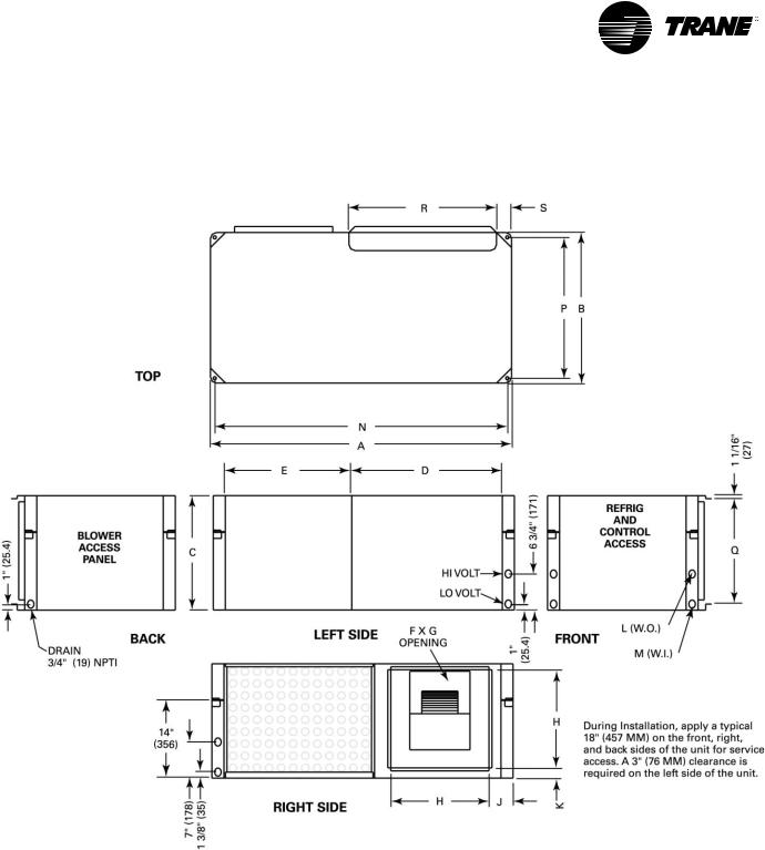
Dimensions/Weights
Right Return/Left Supply
|
|
|
|
|
|
|
|
|
|
|
|
|
|
|
|
|
|
|
|
|
|
|
|
|
|
|
|
|
|
|
|
|
|
|
|
|
|
|
|
Unit |
A |
B |
C |
D |
E |
F |
G |
H |
J |
|
K |
L |
M |
N |
P |
Q |
R |
S |
|
|
NPTI |
NPTI |
|
||||||||||||||||
|
|
|
|
|
|
|
|
|
|
|
|
|
|
|
|
|
|
||
006,009 |
40" |
20" |
15" |
20" |
15" |
6 7/8" |
8" |
11 1/2" |
4 1/4" |
2 |
1/8" |
1/2" |
1/2" |
38 3/4" |
18 3/4" |
13 5/8" |
18 1/2" |
3 3/8" |
|
(1016) |
(508) |
(381) |
(508) |
(381) |
(175) |
(203) |
(292) |
(108) |
(54) |
(12.7) |
(12.7) |
(984) |
(476) |
(346) |
(470) |
(86) |
|
||
012, 015 |
40" |
20" |
15" |
20" |
15" |
6 7/8" |
9 7/8" |
11 1/2" |
4 1/4" |
2 |
5/8" |
1/2" |
1/2" |
38 3/4" |
18 3/4" |
13 5/8" |
18 1/2" |
3 3/8" |
|
(1016) |
(508) |
(381) |
(508) |
(381) |
(175) |
(251) |
(292) |
(108) |
(67) |
(12.7) |
(12.7) |
(984) |
(476) |
(346) |
(470) |
(86) |
|
||
018 |
46" |
23" |
17" |
23" |
18" |
8 1/4" |
9 3/4" |
13 1/2" |
4 3/4" |
2 |
7/8" |
3/4" |
3/4" |
44 3/4" |
21 3/4" |
15 5/8" |
18 1/2" |
4 1/4" |
|
(1168) |
(584) |
(432) |
(584) |
(457) |
(210) |
(248) |
(343) |
(121) |
(73) |
(19) |
(19) |
(1137) |
(552) |
(397) |
(470) |
(108) |
|
||
|
|
||||||||||||||||||
024, 030 |
46" |
23" |
17" |
23" |
18" |
8 1/4" |
11 3/8" |
13 1/2" |
4 3/4" |
2 |
7/8" |
3/4" |
3/4" |
44 3/4" |
21 3/4" |
15 5/8" |
18 1/2" |
4 1/4" |
|
(1168) |
(584) |
(432) |
(584) |
(457) |
(210) |
(289) |
(343) |
(121) |
(73) |
(19) |
(19) |
(1137) |
(552) |
(397) |
(470) |
(108) |
|
||
036, 042 |
50" |
25" |
19" |
25" |
20" |
10 1/2" |
13 1/2" |
16 3/8" |
4" |
1 |
3/4" |
3/4" |
3/4" |
48 3/4" |
23 3/4" |
17 5/8" |
23 1/2" |
3 1/4" |
|
(1270) |
(635) |
(483) |
(635) |
(508) |
(267) |
(343) |
(416) |
(102) |
(45) |
(19) |
(19) |
(1238) |
(603) |
(448) |
(597) |
(83) |
|
||
048, 060 |
58" |
33" |
21" |
25" |
28" |
13 7/8" |
13 7/8" |
18" |
6 5/8" |
|
2" |
1" |
1" |
56 3/4" |
31 3/4" |
19 5/8" |
23 1/2" |
5 1/2" |
|
(1473) |
(838) |
(533) |
(635) |
(711) |
(352) |
(352) |
(457) |
(168) |
(51) |
(25.4) |
(25.4) |
(1441) |
(806) |
(498) |
(597) |
(140) |
|
||
WSHP-SVX01D-EN |
13 |
Dimensions/Weights
Right Return/Back Supply
|
|
|
|
|
|
|
|
|
|
|
|
|
|
|
|
|
|
|
|
|
|
|
|
|
|
|
|
|
|
|
|
|
|
|
|
|
|
|
|
|
|
Unit |
A |
B |
C |
D |
E |
F |
G |
H |
|
J |
|
K |
L |
M |
N |
P |
Q |
R |
S |
|
|
|
NPTI |
NPTI |
|
||||||||||||||||
|
|
|
|
|
|
|
|
|
|
|
|
|
|
|
|
|
|
|
||
006,009 |
40" |
20" |
15" |
20" |
15" |
6 7/8" |
8" |
11 1/2" |
4 |
1/4" |
2 |
1/8" |
1/2" |
1/2" |
38 3/4" |
18 3/4" |
13 5/8" |
18 1/2" |
3 3/8" |
|
(1016) |
(508) |
(381) |
(508) |
(381) |
(175) |
(203) |
(292) |
(108) |
(54) |
(12.7) |
(12.7) |
(984) |
(476) |
(346) |
(470) |
(86) |
|
|||
012, 015 |
40" |
20" |
15" |
20" |
15" |
6 7/8" |
9 7/8" |
11 1/2" |
4 |
1/4" |
2 |
5/8" |
1/2" |
1/2" |
38 3/4" |
18 3/4" |
13 5/8" |
18 1/2" |
3 3/8" |
|
(1016) |
(508) |
(381) |
(508) |
(381) |
(175) |
(251) |
(292) |
(108) |
(67) |
(12.7) |
(12.7) |
(984) |
(476) |
(346) |
(470) |
(86) |
|
|||
018 |
46" |
23" |
17" |
23" |
18" |
8 1/4" |
9 3/4" |
13 1/2" |
4 |
3/4" |
2 |
7/8" |
3/4" |
3/4" |
44 3/4" |
21 3/4" |
15 5/8" |
18 1/2" |
4 1/4" |
|
(1168) |
(584) |
(432) |
(584) |
(457) |
(210) |
(248) |
(343) |
(121) |
(73) |
(19) |
(19) |
(1137) |
(552) |
(397) |
(470) |
(108) |
|
|||
|
|
|||||||||||||||||||
024, 030 |
46" |
23" |
17" |
23" |
18" |
8 1/4" |
11 3/8" |
13 1/2" |
4 |
3/4" |
2 |
7/8" |
3/4" |
3/4" |
44 3/4" |
21 3/4" |
15 5/8" |
18 1/2" |
4 1/4" |
|
(1168) |
(584) |
(432) |
(584) |
(457) |
(210) |
(289) |
(343) |
(121) |
(73) |
(19) |
(19) |
(1137) |
(552) |
(397) |
(470) |
(108) |
|
|||
036, 042 |
50" |
25" |
19" |
25" |
20" |
10 1/2" |
13 1/2" |
16 3/8" |
|
4" |
1 |
3/4" |
3/4" |
3/4" |
48 3/4" |
23 3/4" |
17 5/8" |
23 1/2" |
3 1/4" |
|
(1270) |
(635) |
(483) |
(635) |
(508) |
(267) |
(343) |
(416) |
(102) |
(45) |
(19) |
(19) |
(1238) |
(603) |
(448) |
(597) |
(83) |
|
|||
048, 060 |
58" |
33" |
21" |
25" |
28" |
13 7/8" |
13 7/8" |
18" |
6 |
5/8" |
|
2" |
1" |
1" |
56 3/4" |
31 3/4" |
19 5/8" |
23 1/2" |
5 1/2" |
|
(1473) |
(838) |
(533) |
(635) |
(711) |
(352) |
(352) |
(457) |
(168) |
(51) |
(25.4) |
(25.4) |
(1441) |
(806) |
(498) |
(597) |
(140) |
|
|||
14 |
WSHP-SVX01D-EN |
Dimensions/Weights
Right Return/Right Supply
|
|
|
|
|
|
|
|
|
|
|
|
|
|
|
|
|
|
|
|
|
|
|
|
|
|
|
|
|
|
|
|
|
|
|
|
|
|
|
|
|
|
Unit |
A |
B |
C |
D |
E |
F |
G |
H |
|
J |
|
K |
L |
M |
N |
P |
Q |
R |
S |
|
|
|
NPTI |
NPTI |
|
||||||||||||||||
|
|
|
|
|
|
|
|
|
|
|
|
|
|
|
|
|
|
|
||
006,009 |
40" |
20" |
15" |
20" |
15" |
6 7/8" |
8" |
11 1/2" |
4 |
1/4" |
2 |
1/8" |
1/2" |
1/2" |
38 3/4" |
18 3/4" |
13 5/8" |
18 1/2" |
3 3/8" |
|
(1016) |
(508) |
(381) |
(508) |
(381) |
(175) |
(203) |
(292) |
(108) |
(54) |
(12.7) |
(12.7) |
(984) |
(476) |
(346) |
(470) |
(86) |
|
|||
012, 015 |
40" |
20" |
15" |
20" |
15" |
6 7/8" |
9 7/8" |
11 1/2" |
4 |
1/4" |
2 |
5/8" |
1/2" |
1/2" |
38 3/4" |
18 3/4" |
13 5/8" |
18 1/2" |
3 3/8" |
|
(1016) |
(508) |
(381) |
(508) |
(381) |
(175) |
(251) |
(292) |
(108) |
(67) |
(12.7) |
(12.7) |
(984) |
(476) |
(346) |
(470) |
(86) |
|
|||
018 |
46" |
23" |
17" |
23" |
18" |
8 1/4" |
9 3/4" |
13 1/2" |
4 |
3/4" |
2 |
7/8" |
3/4" |
3/4" |
44 3/4" |
21 3/4" |
15 5/8" |
18 1/2" |
4 1/4" |
|
(1168) |
(584) |
(432) |
(584) |
(457) |
(210) |
(248) |
(343) |
(121) |
(73) |
(19) |
(19) |
(1137) |
(552) |
(397) |
(470) |
(108) |
|
|||
|
|
|||||||||||||||||||
024, 030 |
46" |
23" |
17" |
23" |
18" |
8 1/4" |
11 3/8" |
13 1/2" |
4 |
3/4" |
2 |
7/8" |
3/4" |
3/4" |
44 3/4" |
21 3/4" |
15 5/8" |
18 1/2" |
4 1/4" |
|
(1168) |
(584) |
(432) |
(584) |
(457) |
(210) |
(289) |
(343) |
(121) |
(73) |
(19) |
(19) |
(1137) |
(552) |
(397) |
(470) |
(108) |
|
|||
036, 042 |
50" |
25" |
19" |
25" |
20" |
10 1/2" |
13 1/2" |
16 3/8" |
|
4" |
1 |
3/4" |
3/4" |
3/4" |
48 3/4" |
23 3/4" |
17 5/8" |
23 1/2" |
3 1/4" |
|
(1270) |
(635) |
(483) |
(635) |
(508) |
(267) |
(343) |
(416) |
(102) |
(45) |
(19) |
(19) |
(1238) |
(603) |
(448) |
(597) |
(83) |
|
|||
048, 060 |
58" |
33" |
21" |
25" |
28" |
13 7/8" |
13 7/8" |
18" |
6 |
5/8" |
|
2" |
1" |
1" |
56 3/4" |
31 3/4" |
19 5/8" |
23 1/2" |
5 1/2" |
|
(1473) |
(838) |
(533) |
(635) |
(711) |
(352) |
(352) |
(457) |
(168) |
(51) |
(25.4) |
(25.4) |
(1441) |
(806) |
(498) |
(597) |
(140) |
|
|||
WSHP-SVX01D-EN |
15 |
Dimensions/Weights
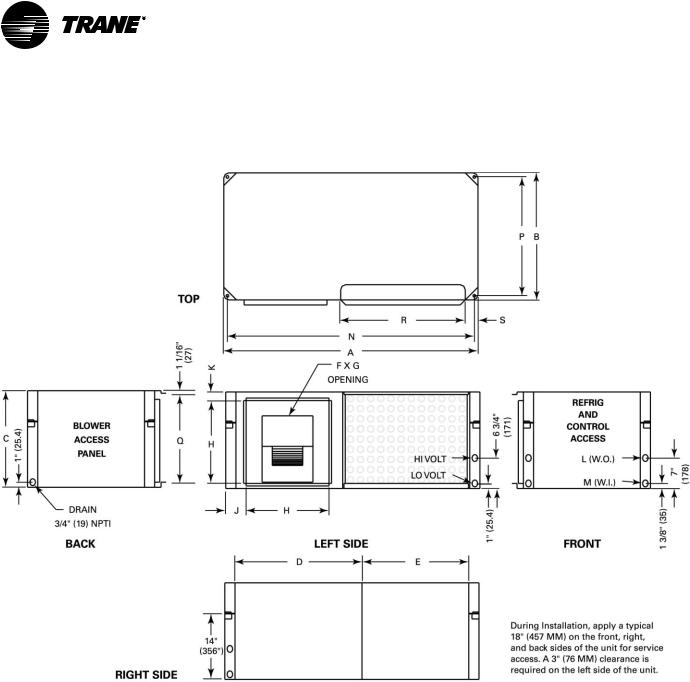
Left Return/Top Supply
|
|
|
|
|
|
|
|
|
|
|
|
|
|
|
|
|
|
|
|
|
|
|
|
|
|
|
|
|
|
|
|
|
|
|
|
|
|
Unit |
A |
B |
C |
D |
E |
F |
G |
H |
J |
K |
L |
M |
N |
W.I. |
W.O. |
Drain |
||
GEV |
NPTI |
NPTI |
FPT |
|||||||||||||||
|
|
|
|
|
|
|
|
|
|
|
|
|
|
|||||
006-015 |
19 1/2" |
31 1/4" |
21 1/2" |
11 1/2" |
4" |
3 3/4" |
16 1/2" |
15" |
18" |
6 7/8" |
8" |
3/4" |
2" |
1/2" |
1/2" |
3/4" |
||
(495) |
(794) |
(546) |
(292) |
(102) |
(95) |
(419) |
(381) |
(457) |
(175) |
(203) |
(19) |
(51) |
(12.7) |
(12.7) |
(19) |
|||
|
||||||||||||||||||
|
|
|
|
|
|
|
|
|
|
|
|
9 3/4" |
|
|
|
|
|
|
018, 024, |
21 1/2" |
39 1/4" |
21 1/2" |
13 1/2" |
4" |
4" |
17 1/2" |
23 3/4" |
17" |
8 1/4" |
(248) |
3/4" |
2" |
3/4" |
3/4" |
3/4" |
||
030, 040 |
(546) |
(997) |
(546) |
(343) |
(102) |
(1021) |
(445) |
(603) |
(432) |
(368) |
11 3/8" |
(19) |
(51) |
(19) |
(19) |
(19) |
||
|
|
|
|
|
|
|
|
|
|
|
|
(289) |
|
|
|
|
|
|
036, 042 |
24 1/2" |
41 7/8" |
26 1/2" |
18" |
3 1/4" |
1 7/8" |
19 1/2" |
19" |
23" |
10 1/2" |
13 1/2" |
1 3/4" |
0 |
3/4" |
3/4" |
3/4" |
||
(622) |
(1064) |
(673) |
(457) |
(83) |
(48) |
(495) |
(483) |
(584) |
(267) |
(343) |
(19) |
(19) |
(19) |
(19) |
||||
|
|
|||||||||||||||||
Std-048 |
26 1/2" |
46 7/8" |
30 1/2" |
18" |
4 1/4" |
2" |
21 1/2" |
29" |
27" |
13 7/8" |
13 7/8" |
2 1/4" |
3 1/2" |
1" |
1" |
3/4" |
||
(673) |
(1191) |
(775) |
(457) |
(108) |
(51) |
(546) |
(737) |
(686) |
(352) |
(352) |
(57) |
(89) |
(25.4) |
(25.4) |
(19) |
|||
|
||||||||||||||||||
Hi-048, |
26 1/2" |
46 7/8" |
30 1/2" |
18" |
4 1/4" |
2" |
21 1/2" |
29" |
27" |
13 1/8" |
11 3/8" |
2 1/4" |
3 1/2" |
1" |
1" |
3/4" |
||
060 |
(673) |
(1191) |
(775) |
(457) |
(108) |
(51) |
(546) |
(737) |
(686) |
(333) |
(289) |
(57) |
(89) |
(25.4) |
(25.4) |
(19) |
||
16 |
WSHP-SVX01D-EN |
Dimensions/Weights
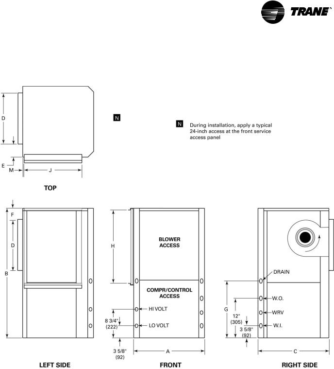
Left Return/Back Supply
|
|
|
|
|
|
|
|
|
|
|
|
|
|
|
|
|
|
|
|
|
|
|
|
|
|
|
|
|
|
|
|
|
|
|
|
|
|
Unit |
A |
B |
C |
D |
|
E |
F |
G |
H |
J |
K |
L |
M |
N |
W.I. |
W.O. |
Drain |
|
GEV |
|
NPTI |
NPTI |
FPT |
|
|||||||||||||
|
|
|
|
|
|
|
|
|
|
|
|
|
|
|
||||
006-015 |
19 1/2" |
31 1/4" |
21 1/2" |
11 1/2" |
4" |
3 3/4" |
16 1/2" |
15" |
18" |
6 7/8" |
8" |
3/4" |
2" |
1/2" |
1/2" |
3/4" |
|
|
(495) |
(794) |
(546) |
(292) |
(102) |
(95) |
(419) |
(381) |
(457) |
(175) |
(203) |
(19) |
(51) |
(12.7) |
(12.7) |
(19) |
|
||
|
|
|||||||||||||||||
|
|
|
|
|
|
|
|
|
|
|
|
9 3/4" |
|
|
|
|
|
|
018, 024, |
21 1/2" |
39 1/4" |
21 1/2" |
13 1/2" |
4" |
4" |
17 1/2" |
23 3/4" |
17" |
8 1/4" |
(248) |
3/4" |
2" |
3/4" |
3/4" |
3/4" |
|
|
030, 040 |
(546) |
(997) |
(546) |
(343) |
(102) |
(1021) |
(445) |
(603) |
(432) |
(368) |
11 3/8" |
(19) |
(51) |
(19) |
(19) |
(19) |
|
|
|
|
|
|
|
|
|
|
|
|
|
|
(289) |
|
|
|
|
|
|
036, 042 |
24 1/2" |
41 7/8" |
26 1/2" |
18" |
3 1/4" |
1 7/8" |
19 1/2" |
19" |
23" |
10 1/2" |
13 1/2" |
1 3/4" |
0 |
3/4" |
3/4" |
3/4" |
|
|
(622) |
(1064) |
(673) |
(457) |
(83) |
(48) |
(495) |
(483) |
(584) |
(267) |
(343) |
(19) |
(19) |
(19) |
(19) |
|
|||
|
|
|
||||||||||||||||
Std-048 |
26 1/2" |
46 7/8" |
30 1/2" |
18" |
4 1/4" |
2" |
21 1/2" |
29" |
27" |
13 7/8" |
13 7/8" |
2 1/4" |
3 1/2" |
1" |
1" |
3/4" |
|
|
(673) |
(1191) |
(775) |
(457) |
(108) |
(51) |
(546) |
(737) |
(686) |
(352) |
(352) |
(57) |
(89) |
(25.4) |
(25.4) |
(19) |
|
||
|
|
|||||||||||||||||
Hi-048, |
26 1/2" |
46 7/8" |
30 1/2" |
18" |
4 1/4" |
2" |
21 1/2" |
29" |
27" |
13 1/8" |
11 3/8" |
2 1/4" |
3 1/2" |
1" |
1" |
3/4" |
|
|
060 |
(673) |
(1191) |
(775) |
(457) |
(108) |
(51) |
(546) |
(737) |
(686) |
(333) |
(289) |
(57) |
(89) |
(25.4) |
(25.4) |
(19) |
|
|
WSHP-SVX01D-EN |
17 |
Dimensions/Weights
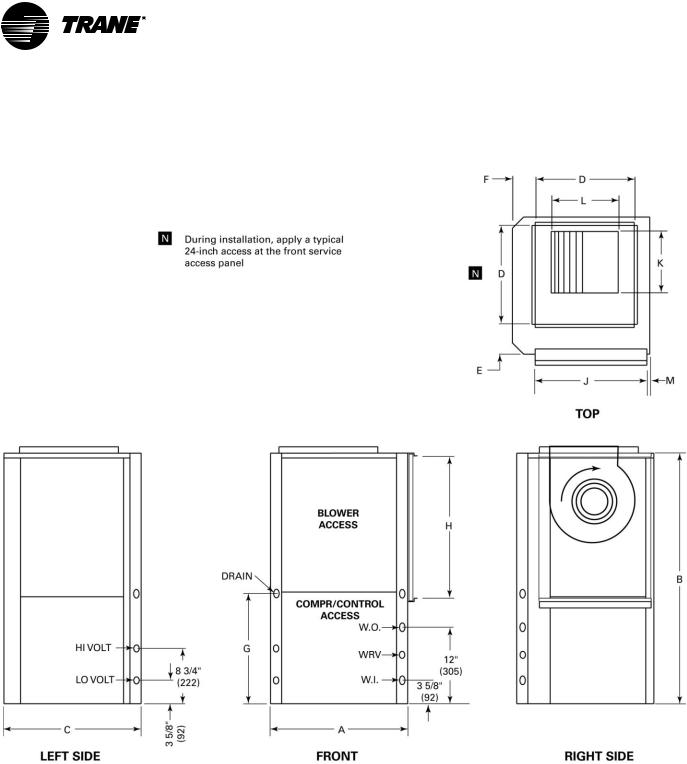
Right Return/Top Supply
|
|
|
|
|
|
|
|
|
|
|
|
|
|
|
|
|
|
|
|
|
|
|
|
|
|
|
|
|
|
|
|
|
|
|
|
|
|
Unit |
A |
B |
C |
D |
E |
F |
G |
H |
J |
K |
L |
M |
N |
W.I. |
W.O. |
Drain |
||
GEV |
NPTI |
NPTI |
FPT |
|||||||||||||||
|
|
|
|
|
|
|
|
|
|
|
|
|
|
|||||
006-015 |
19 1/2" |
31 1/4" |
21 1/2" |
11 1/2" |
4" |
3 3/4" |
16 1/2" |
15" |
18" |
6 7/8" |
8" |
3/4" |
2" |
1/2" |
1/2" |
3/4" |
||
(495) |
(794) |
(546) |
(292) |
(102) |
(95) |
(419) |
(381) |
(457) |
(175) |
(203) |
(19) |
(51) |
(12.7) |
(12.7) |
(19) |
|||
|
||||||||||||||||||
|
|
|
|
|
|
|
|
|
|
|
|
9 3/4" |
|
|
|
|
|
|
018, 024, |
21 1/2" |
39 1/4" |
21 1/2" |
13 1/2" |
4" |
4" |
17 1/2" |
23 3/4" |
17" |
8 1/4" |
(248) |
3/4" |
2" |
3/4" |
3/4" |
3/4" |
||
030, 040 |
(546) |
(997) |
(546) |
(343) |
(102) |
(1021) |
(445) |
(603) |
(432) |
(368) |
11 3/8" |
(19) |
(51) |
(19) |
(19) |
(19) |
||
|
|
|
|
|
|
|
|
|
|
|
|
(289) |
|
|
|
|
|
|
036, 042 |
24 1/2" |
41 7/8" |
26 1/2" |
18" |
3 1/4" |
1 7/8" |
19 1/2" |
19" |
23" |
10 1/2" |
13 1/2" |
1 3/4" |
0 |
3/4" |
3/4" |
3/4" |
||
(622) |
(1064) |
(673) |
(457) |
(83) |
(48) |
(495) |
(483) |
(584) |
(267) |
(343) |
(19) |
(19) |
(19) |
(19) |
||||
|
|
|||||||||||||||||
Std-048 |
26 1/2" |
46 7/8" |
30 1/2" |
18" |
4 1/4" |
2" |
21 1/2" |
29" |
27" |
13 7/8" |
13 7/8" |
2 1/4" |
3 1/2" |
1" |
1" |
3/4" |
||
(673) |
(1191) |
(775) |
(457) |
(108) |
(51) |
(546) |
(737) |
(686) |
(352) |
(352) |
(57) |
(89) |
(25.4) |
(25.4) |
(19) |
|||
|
||||||||||||||||||
Hi-048, |
26 1/2" |
46 7/8" |
30 1/2" |
18" |
4 1/4" |
2" |
21 1/2" |
29" |
27" |
13 1/8" |
11 3/8" |
2 1/4" |
3 1/2" |
1" |
1" |
3/4" |
||
060 |
(673) |
(1191) |
(775) |
(457) |
(108) |
(51) |
(546) |
(737) |
(686) |
(333) |
(289) |
(57) |
(89) |
(25.4) |
(25.4) |
(19) |
||
18 |
WSHP-SVX01D-EN |
Dimensions/Weights
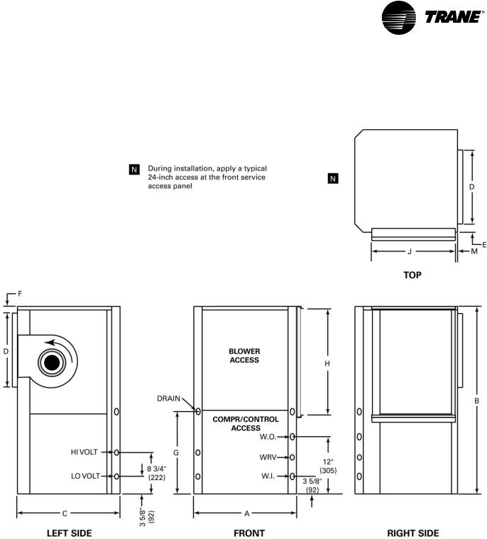
Right Return/Back Supply
|
|
|
|
|
|
|
|
|
|
|
|
|
|
|
|
|
|
|
|
|
|
|
|
|
|
|
|
|
|
|
|
|
|
|
|
|
|
Unit |
A |
B |
C |
D |
|
E |
F |
G |
H |
J |
K |
L |
M |
N |
W.I. |
W.O. |
Drain |
|
GEV |
|
NPTI |
NPTI |
FPT |
|
|||||||||||||
|
|
|
|
|
|
|
|
|
|
|
|
|
|
|
||||
006-015 |
19 1/2" |
31 1/4" |
21 1/2" |
11 1/2" |
4" |
3 3/4" |
16 1/2" |
15" |
18" |
6 7/8" |
8" |
3/4" |
2" |
1/2" |
1/2" |
3/4" |
|
|
(495) |
(794) |
(546) |
(292) |
(102) |
(95) |
(419) |
(381) |
(457) |
(175) |
(203) |
(19) |
(51) |
(12.7) |
(12.7) |
(19) |
|
||
|
|
|||||||||||||||||
|
|
|
|
|
|
|
|
|
|
|
|
9 3/4" |
|
|
|
|
|
|
018, 024, |
21 1/2" |
39 1/4" |
21 1/2" |
13 1/2" |
4" |
4" |
17 1/2" |
23 3/4" |
17" |
8 1/4" |
(248) |
3/4" |
2" |
3/4" |
3/4" |
3/4" |
|
|
030, 040 |
(546) |
(997) |
(546) |
(343) |
(102) |
(1021) |
(445) |
(603) |
(432) |
(368) |
11 3/8" |
(19) |
(51) |
(19) |
(19) |
(19) |
|
|
|
|
|
|
|
|
|
|
|
|
|
|
(289) |
|
|
|
|
|
|
036, 042 |
24 1/2" |
41 7/8" |
26 1/2" |
18" |
3 1/4" |
1 7/8" |
19 1/2" |
19" |
23" |
10 1/2" |
13 1/2" |
1 3/4" |
0 |
3/4" |
3/4" |
3/4" |
|
|
(622) |
(1064) |
(673) |
(457) |
(83) |
(48) |
(495) |
(483) |
(584) |
(267) |
(343) |
(19) |
(19) |
(19) |
(19) |
|
|||
|
|
|
||||||||||||||||
Std-048 |
26 1/2" |
46 7/8" |
30 1/2" |
18" |
4 1/4" |
2" |
21 1/2" |
29" |
27" |
13 7/8" |
13 7/8" |
2 1/4" |
3 1/2" |
1" |
1" |
3/4" |
|
|
(673) |
(1191) |
(775) |
(457) |
(108) |
(51) |
(546) |
(737) |
(686) |
(352) |
(352) |
(57) |
(89) |
(25.4) |
(25.4) |
(19) |
|
||
|
|
|||||||||||||||||
Hi-048, |
26 1/2" |
46 7/8" |
30 1/2" |
18" |
4 1/4" |
2" |
21 1/2" |
29" |
27" |
13 1/8" |
11 3/8" |
2 1/4" |
3 1/2" |
1" |
1" |
3/4" |
|
|
060 |
(673) |
(1191) |
(775) |
(457) |
(108) |
(51) |
(546) |
(737) |
(686) |
(333) |
(289) |
(57) |
(89) |
(25.4) |
(25.4) |
(19) |
|
|
WSHP-SVX01D-EN |
19 |
Dimensional Data
GEH-Right Return/Left Supply
GEH 072-120 (60 Hz)
GEH 072-090 (50 Hz)
GEH |
GEH |
A |
B |
C |
D |
|
60 Hz |
50 Hz |
|||||
|
|
|
|
|||
072 |
- |
36 1/4" |
15 5/8" |
6 5/8" |
1 1/4" |
|
(921) |
(397) |
(168) |
(32) |
|||
|
|
|||||
090 |
072 |
36 1/8" |
12 3/4" |
6 3/4" |
1 1/4" |
|
(917) |
(324) |
(171) |
(32) |
|||
|
|
|||||
120 |
090 |
36 1/8" |
13" |
7 1/4" |
1 1/2" |
|
(917) |
(330) |
(184) |
(38) |
|||
|
|
20 |
WSHP-SVX01D-EN |
Dimensional Data
GEH-Right Return/Back Supply
GEH 072-120 (60 Hz)
GEH 072-090 (50 Hz)
GEH |
GEH |
A |
B |
C |
D |
|
60 Hz |
50 Hz |
|||||
|
|
|
|
|||
072 |
- |
36 1/4" |
15 5/8" |
6 5/8" |
1 1/4" |
|
(921) |
(397) |
(168) |
(32) |
|||
|
|
|||||
090 |
072 |
36 1/8" |
12 3/4" |
6 3/4" |
1 1/4" |
|
(917) |
(324) |
(171) |
(32) |
|||
|
|
|||||
120 |
090 |
36 1/8" |
13" |
7 1/4" |
1 1/2" |
|
(917) |
(330) |
(184) |
(38) |
|||
|
|
WSHP-SVX01D-EN |
21 |

Dimensional Data
GEH-Left Return/Right Supply
GEH 072-120 (60 Hz)
GEH 072-090 (50 Hz)
GEH |
GEH |
A |
B |
C |
D |
|
60 Hz |
50 Hz |
|||||
|
|
|
|
|||
072 |
- |
36 1/8" |
17" |
8" |
1 1/4" |
|
(917) |
(432) |
(203) |
(32) |
|||
|
|
|||||
090 |
072 |
36 1/8" |
13 3/4" |
7 3/4" |
1 1/4" |
|
(917) |
(349) |
(197) |
(32) |
|||
|
|
|||||
120 |
090 |
36 1/8" |
13" |
7 1/4" |
1 1/2" |
|
(917) |
(330) |
(184) |
(38) |
|||
|
|
22 |
WSHP-SVX01D-EN |
Dimensional Data
GEH-Left Return/Back Supply
GEH 072-120 (60 Hz)
GEH 072-090 (50 Hz)
GEH |
GEH |
A |
B |
C |
D |
|
60 Hz |
50 Hz |
|||||
|
|
|
|
|||
072 |
- |
36 1/8" |
17" |
8" |
1 1/4" |
|
(917) |
(432) |
(203) |
(32) |
|||
|
|
|||||
090 |
072 |
36 1/8" |
13 3/4" |
7 3/4" |
1 1/4" |
|
(917) |
(349) |
(197) |
(32) |
|||
|
|
|||||
120 |
090 |
36 1/8" |
13" |
7 1/4" |
1 1/2" |
|
(917) |
(330) |
(184) |
(38) |
|||
|
|
WSHP-SVX01D-EN |
23 |
Dimensional Data
GEH-Right Return/Left Supply
GEH 150-180 (60 Hz)
GEH 120-150 (50 Hz)
24 |
WSHP-SVX01D-EN |
Dimensional Data
GEH-Right Return/Back Supply
GEH 150-180 (60 Hz)
GEH 120-150 (50 Hz)
WSHP-SVX01D-EN |
25 |
Dimensional Data
GEH-Left Return/Right Supply
GEH 150-180 (60 Hz)
GEH 120-150 (60 Hz)
26 |
WSHP-SVX01D-EN |
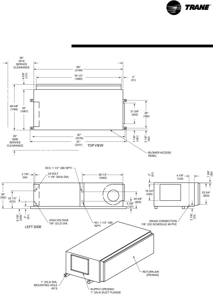
Dimensional Data
GEH-Left Return/Back Supply
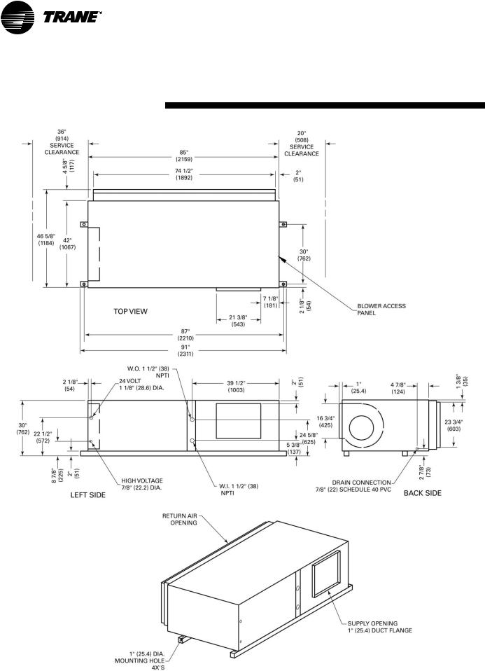
GEH 150-180 (60 Hz)
GEH 120-150 (50 Hz)
WSHP-SVX01D-EN |
27 |
Loading...