


ADJUSTABLE SPEED DRIVE NETWORK INTERFACE
ICC
INDUSTRIAL CONTROL COMMUNICATIONS, INC.
ETH-100
ETHERNET COMMUNICATIONS INTERFACE FOR THE TOSHIBA 7-SERIES AND 9-SERIES ADJUSTABLE SPEED DRIVES
April 2002
ICC #10449-1.100-000

Introduction
Thank you for purchasing the ICC, Inc. ETH-100 Ethernet Communications Interface for the Toshiba 7-Series and 9-Series Adjustable Speed Drives. Before using the ETH-100 interface, please familiarize yourself with the product and be sure to thoroughly read the instructions and precautions contained in this manual. In addition, please make sure that this instruction manual is delivered to the end user of the drive units with which the ETH-100 interface is connected, and keep this instruction manual in a safe place for future reference or drive/interface inspection.
This instruction manual describes the device specifications, wiring methods, maintenance procedures, supported functions and usage methods for the ETH-100 Ethernet communications interface.
In conjunction with this manual, the following manuals are supplied by Toshiba, and are essential both for ensuring a safe, reliable system installation as well as for realizing the full potential of the ETH-100 interface:
•Toshiba TOSVERT VF-S7 Series Instruction Manual
•Toshiba TOSVERT VF-S9 Series Instruction Manual
•Toshiba TOSVERT VF-A7 Series Instruction Manual
•Toshiba G7 Series Operation Manual
•Toshiba VF-S7 Industrial Inverter Serial Communications Option Manual
If you do not have copies available of the documents relevant to your installation, please contact Toshiba or your local Toshiba distributor to obtain them, or copies may be downloaded from http://www.tic.toshiba.com (subject to availability).
Before continuing, please take a moment to ensure that you have received all materials shipped with your kit. These items are:
•External ETH-100 interface in DIN rail mountable case
•2 meter DB9-RJ45 MMI port cable (part number 10425)
•This manual
1

ETH-100 Ethernet Interface User's Manual
Part Number 10449-1.100-000
Printed in U.S.A.
©2001-2002 Industrial Control Communications, Inc.
All rights reserved
Industrial Control Communications, Inc. reserves the right to make changes and improvements to its products without providing notice.
Notice to Users
INDUSTRIAL CONTROL COMMUNICATIONS, INC.’S PRODUCTS ARE NOT AUTHORIZED FOR USE AS CRITICAL COMPONENTS IN LIFE-SUPPORT DEVICES OR SYSTEMS. Life-support devices or systems are devices or systems intended to sustain life, and whose failure to perform, when properly used in accordance with instructions for use provided in the labeling and user's manual, can be reasonably expected to result in significant injury.
No complex software or hardware system is perfect. Bugs may always be present in a system of any size. In order to prevent danger to life or property, it is the responsibility of the system designer to incorporate redundant protective mechanisms appropriate to the risk involved.
2

Usage Precautions
Operating Environment
•Please use the ETH-100 only when the ambient temperature of the environment into which the ETH-100 is installed is within the following specified temperature limits:
Operation: -10 +50° C (+14 +122° F)
Storage: -40 +85° C (-40 +185° F)
•Avoid installation locations that may be subjected to large shocks or vibrations.
•Avoid installation locations that may be subjected to rapid changes in temperature or humidity.
Installation • Wiring
•Do not touch charged parts of the drive such as the terminal block while the drive’s CHARGE lamp is lit. A charge will still be present in the drive’s internal electrolytic capacitors, and therefore touching these areas may result in an electrical shock. Always turn all drive input power supplies OFF, and wait at least 5 minutes after the CHARGE lamp has gone out before connecting communication cables or motor wiring.
•Proper ground connections are vital for both safety and signal reliability reasons. For proper grounding procedures, please refer to the section in this manual pertaining to grounding (section 4).
•Route all communication cables separate from the drive’s input/output power wiring.
•To avoid the possibility of electric shock due to leakage currents, always ground the drive’s E/GND terminal and the motor. To avoid misoperation, do not connect the ETH-100’s GND terminal to either of the above-mentioned grounds or any other power ground.
•When making connections between the ETH-100 and the drives, do not use cables that exceed 5 meters in length.
•For further drive-specific precaution, safety and installation information, please refer to the appropriate Toshiba documentation supplied with your drive.
Other Precautions
•Internal drive EEPROMs have a limited life span of write cycles. Observe all precautions contained in this manual and Toshiba manuals regarding which drive registers safely may and may not be repetitively written to.
•Do not touch or insert a rod or any other item into the ETH-100’s case while power is applied, as this may lead to electrical shock or device damage.
•Commission the disposal of the ETH-100 to a specialist.
•Because the ETH-100 derives its control power from the connected drives, removing power to all connected drives will also cause the ETH-100 to lose power.
3

TABLE OF CONTENTS
1. |
Mechanical Diagrams........................................................................... |
6 |
|
1.1 |
Enclosure ......................................................................................................... |
6 |
|
1.2 |
Mounting Clip ................................................................................................... |
7 |
|
1.3 |
External Interface ............................................................................................. |
8 |
|
2. |
Feature Summary ................................................................................. |
9 |
|
3. |
Installing The Interface ...................................................................... |
12 |
|
3.1 |
Installation for G7 Drives ................................................................................ |
12 |
|
3.2 |
Installation for S7, S9 and A7 Drives.............................................................. |
13 |
|
4. |
Grounding ........................................................................................... |
15 |
|
5. |
Environmental Specifications ........................................................... |
16 |
|
6. |
Maintenance And Inspection............................................................. |
17 |
|
7. |
Storage And Warranty........................................................................ |
18 |
|
7.1 |
Storage .......................................................................................................... |
18 |
|
7.2 |
Warranty ........................................................................................................ |
18 |
|
8. |
Console Configuration....................................................................... |
19 |
|
8.1 |
RS232 ............................................................................................................ |
19 |
|
8.1.1 |
Requirements.......................................................................................... |
19 |
|
8.1.2 |
Connection.............................................................................................. |
19 |
|
8.1.3 |
Application Configuration ........................................................................ |
19 |
|
8.2 |
Telnet............................................................................................................. |
21 |
|
8.2.1 |
Requirements.......................................................................................... |
21 |
|
8.2.2 |
Connection.............................................................................................. |
21 |
|
8.2.3 |
Application Configuration ........................................................................ |
21 |
|
8.3 |
Command Overview....................................................................................... |
22 |
|
8.4 |
Console Configuration Backup....................................................................... |
24 |
|
9. |
LED Indicators .................................................................................... |
25 |
|
9.1 |
Module and Ethernet Indicators...................................................................... |
25 |
|
9.2 |
Drive Connector Indicators............................................................................. |
25 |
|
9.3 |
MMI Connector Indicators .............................................................................. |
26 |
|
10. |
Modbus TCP/IP ................................................................................... |
27 |
|
10.1 |
|
Drive Channel Access ................................................................................ |
27 |
10.2 |
|
Supported Modbus Functions ..................................................................... |
27 |
10.3 |
|
Modbus/Drive Register Mappings ............................................................... |
28 |
|
|
4 |
|

10.4 |
Register Remap Function ........................................................................... |
29 |
10.5 |
ASD Scan Registers ................................................................................... |
30 |
10.6 |
Modbus Programmable Pointer Registers .................................................. |
30 |
10.7 |
Register Access Notes ............................................................................... |
31 |
10.8 |
Performance Tips ....................................................................................... |
32 |
10.9 |
Exceptions and Troubleshooting................................................................. |
34 |
11. Embedded Web Server....................................................................... |
35 |
|
11.1 |
Setup Page................................................................................................. |
36 |
11.2 |
Modbus Page ............................................................................................. |
37 |
11.3 |
Channels Page ........................................................................................... |
38 |
11.3.1 |
Channel Select........................................................................................ |
39 |
11.3.2 ASD Scan Register Configuration ........................................................... |
40 |
|
11.3.3 Programmable Pointer Registers Configuration ...................................... |
41 |
|
11.3.4 |
Drive Test Commands............................................................................. |
42 |
12. |
Firmware Updates............................................................................... |
43 |
|
12.1 |
|
Requirements ............................................................................................. |
43 |
12.2 |
|
Connection ................................................................................................. |
43 |
12.3 |
|
Using The RFU Utility ................................................................................. |
44 |
12.3.1 |
Required Files ......................................................................................... |
44 |
|
12.3.2 |
First-time configuration............................................................................ |
44 |
|
12.3.3 |
Transmitting Firmware Files .................................................................... |
46 |
|
12.4 |
|
Wrap-Up ..................................................................................................... |
46 |
13. |
Notes.................................................................................................... |
48 |
|
5
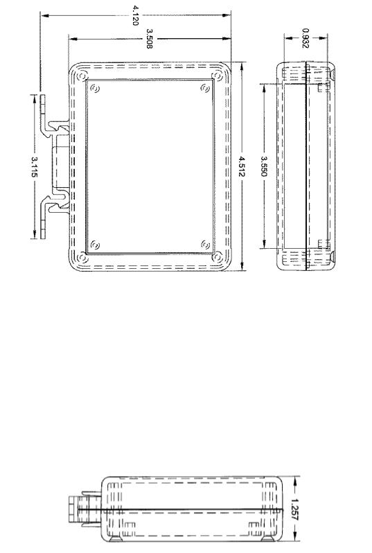
1. Mechanical Diagrams
1.1 Enclosure
(All units are in inches)
6
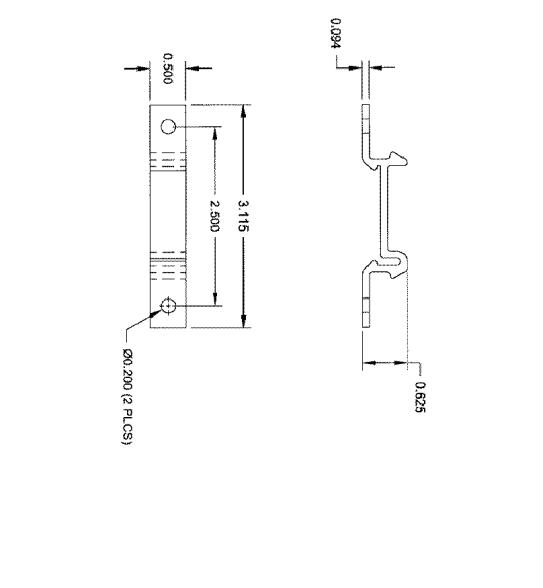
1.2 Mounting Clip
(All units are in inches)
7

1.3 External Interface
MMI port
Network Link/Act LEDs 
Module Status /
Network Status LEDs
ASD Channel A
ASD Channel B
ASD Channel C
|
Configuration |
|
|
|
DIP switches |
|
|
|
|
|
|
|
|
|
|
Ethernet Network |
|
SHIELD grounding terminal |
|
|
|
|
(refer to Section 4). |
|
|
||
Note that for clarity the above diagram shows the ETH-100 unit removed from its case. However, it is not necessary to remove the unit from its case in order to install or configure the ETH-100.
8

2. Feature Summary
The ETH-100 interface provides a wide array of network data access and drive control features. Combined with the flexible configuration and standard 10BaseT Ethernet/Internet connectivity, this allows powerful networked control and monitoring systems to be designed. This in turn provides easy and direct data transfer capabilities to PLCs, PC-based control systems and a wide array of manufacturing/ERP and plant control software packages.
Network
IEEE 802.3 10BaseT Ethernet compliant. Shielded RJ45 connector accepts standard CAT5-type 8-conductor unshielded twisted-pair (UTP) patch cables.
Drive Connections
The ETH-100 provides support for simultaneous connection of three Toshiba 7-series or 9-series drives via the drives’ common serial (aka logic level) communication ports. All drives share a common IP address. Drive connections use the same standard RJ45 style 8-conductor UTP patch cables: any standard CAT5 Ethernet cable (found in most electronics stores) 5 meters or less in length can be used to connect the ETH-100 to the drives.
Power Supply
Self-contained. Powered directly from the connected drives. Drives can be connected to the ETH-100 on any channel (A, B or C) in any order or combination. When more than 1 drive is connected to the unit, the ETH-100 will draw its control power from the drive with the highest power supply voltage.
Supported Protocols
Current support for Schneider Electric Modbus TCP/IP, release 1.0. Conformance Class 0 and partial Class 1 compliant. Allows up to 8 simultaneous Modbus TCP/IP client connections.
Text-Based Console Configuration
The unit can be configured via a simple text-based console interface, available locally over RS232 by using the enclosed MMI cable or remotely over Ethernet via a telnet session.
Embedded Web Server
Unit configuration and drive monitoring and control are also provided via an embedded web server using the HTTP protocol. The ETH-100’s web server feature provides direct access and control via standard web browsers such as Microsoft Internet Explorer and Netscape Navigator.
9
Drive AutoScan Algorithm
Connections to the drives are automatically established and continuously monitored. No drive configuration needs to be performed to connect the ETH-100 to the drives. Just plug it in – it’s that simple.
User-Configurable Scan Registers
In order to provide faster access to internal drive data, the user has the ability to program up to 8 ASD registers per channel to be locally mirrored within the ETH-100. This greatly increases the speed with which accesses to these registers can be made by the network master.
Programmable Pointer Registers
16 Modbus programmable pointer registers are provided to allow “bundling” of disassociated registers. This allows registers which may be scattered around the Modbus register map to be accessed by issuing only 1 Modbus transaction request. When combined with the user-configurable scan registers, this feature provides accessibility of any combination of ASD registers with fast response in a single Modbus transaction.
Indicators
•1 green “LNK” LED that is on whenever a valid Ethernet connection is detected.
•1 red “ACT” LED that flashes whenever data is transferred across the Ethernet network.
•1 bicolor red/green “MS” LED that indicates module status information.
•1 bicolor red/green “NS” LED that indicates network status information.
•2 green LEDs on each of the drive communication connectors and on the MMI port connector.
Refer to section 9 for more detailed information about the LED indicators and their meanings.
Selectable Grounding
Switch SW1 #2 allows the ground plane to be split into 2 different sections: one for the main control circuitry and another for the Ethernet network connector shield and associated magnetics. The latter ground point is accessible for external termination via the GND screw terminal located on the bottom of the unit. Refer to section 4 for more information related to grounding.
MMI Port Connector
RS232-level. Use the DB9-to-RJ45 MMI cable supplied with the ETH-100 kit to interface with the unit for either console-based configuration or flash firmware downloading.
10

Field-Upgradeable
As new firmware becomes available, the ETH-100 unit can be upgraded in the field by the end-user. Refer to section 12 for more information.
Versatile 3-Way DIN-Rail Mounting System
The unit’s enclosure is provided with a mounting clip attached to the rear of the unit. This clip allows the unit to be mounted 3 different ways:
•For DIN rail mounting, snap the mounting clip onto a standard DIN rail, and then snap the unit enclosure onto the clip’s retaining tabs. This allows easy removal or repositioning of the unit on the DIN rail during wiring.
•For panel mounting, the mounting clip can be bolted directly to a flat panel via the two bolt holes at the top and bottom of the clip. Refer to section 1.2 for mounting clip mechanical details. Once the mounting clip is securely attached to the panel, the unit enclosure can be snapped onto the clip’s retaining tabs.
•For fixed DIN rail mounting, a combination of the above two techniques can be employed. First, snap the mounting clip onto a DIN rail and position it in its desired location. Then, the mounting clip can be bolted to the DIN rail support panel, securing it in place. Lastly, the unit can be snapped onto the fixed mounting clip.
In all cases, the unit can be easily unsnapped from the mounting clip to temporarily provide easier access to the configuration switches or network connector.
11

3. Installing The Interface
The ETH-100 connects to each drive via the drive’s common serial (logic level) communication port, typically located on either the main drive control board (G7), on the front of the drive enclosure under a small snap-on cover (A7, S9), or on the righthand side of the drive enclosure under a small snap-on cover (S7). Although no drive parameters need to be configured in order to use the ETH-100, it is advantageous to check that the drive’s common serial communication data rate is set to its maximum speed. Because the ETH-100 will communicate to each drive only at the drive’s configured data rate, this will provide the fastest response time for drive- to-network data transfers. For information on checking the drive’s common serial communication data rate, refer to the appropriate manual supplied with your drive.
Note that the common serial communication parameters of each drive are handled independently by the ETH-100, which means that different drive families may be connected to different channels of the unit in any combination, and that the drives connected to each channel may simultaneously communicate to the unit at completely different baud rates, parity settings, etc.
Installation of the ETH-100 Ethernet interface should only be performed by a qualified technician familiar with the maintenance and operation of the connected drives. To install the ETH-100, complete the following steps:
3.1 Installation for G7 Drives
1. CAUTION! Verify that all input power sources to the drives to be connected have been turned OFF and are locked and tagged out.
2. DANGER!
  Wait at least 5 minutes for the drive’s electrolytic capacitors to discharge before proceeding to the next step. Do not touch any internal parts with power applied to the drive, or for at least 5 minutes after power to the drive has been removed. A hazard exists temporarily for electrical shock even if the source power has been removed. Verify that the CHARGE LED has gone out before continuing the installation process.
3.Attach the mounting clip and unit enclosure in your desired manner (refer to page 11 for more information).
4.Remove the drive’s front cover / open the drive’s cabinet door (refer to the appropriate drive manual for instructions how to do this).
5.The drive’s Electronic Operator Interface (EOI) can communicate with the drive via either the RS485/RS232 channel (CNU1/CNU1A) or the common serial channel (CNU2/CNU2A). Because the ETH-100 uses the common serial channel, the EOI must be configured to use the RS485/RS232 channel. If the drive to be connected is currently using CNU2 (on the drive control board) and CNU2A (on the EOI), then this connection must first be switched over to CNU1 (on the drive control board) and CNU1A (on the EOI). Refer to Toshiba’s documentation for any precautions or notices regarding this connection change.
12

If the EOI is already connected via the RS485/RS232 channel, then no change is required.
6.Connect the drive’s common serial communication port (CNU2) to one of the channels (A, B or C) of the ETH-100 with the communication cable (communication cable is not included with the interface kit). When choosing cables for this connection, standard 24 AWG category 5 (CAT5) unshielded twisted-pair (UTP) 8-conductor cables found in Ethernet networks in most office environments can be used. The maximum allowable length for these cables is 5 meters. Although there are many varieties and styles of CAT5 UTP cables available, ICC strongly recommends using only high-quality cables from reputable manufacturers to guarantee optimal noise immunity and cable longevity. Ensure that each end of the cable is fully seated into the modular connector, and route the cable such that it is located well away from any drive input power or motor wiring. Also take care to route the cable away from any sharp edges or positions where it may be pinched.
7.Reinstall the drive’s front cover / close the drive’s cabinet door.
8.Repeat steps 1, 2, 4, 5, 6 and 7 to connect other drives as needed.
9.Connect the Ethernet network cable to the shielded RJ45 connector marked “Network” on the bottom of the unit. If a ground cable is going to be used, attach the ground cable to the screw terminal marked “GND” on the bottom side of the unit (refer to section 4). Ensure that the network cable is fully seated into the modular connector, and route the cable such that it is located well away from any drive input power or motor wiring. Also take care to route the cable away from any sharp edges or positions where it may be pinched.
10.Take a moment to verify that the ETH-100 and all network cables have sufficient clearance from drives, motors, or power-carrying electrical wiring.
11.Turn the power sources to all connected drives ON, and verify that the drives function properly. If the drives do not appear to power up, or do not function properly, immediately turn power OFF. Repeat steps 1 and 2 to remove all power from the drives. Then, verify all connections. Contact ICC or your local drive distributor or manufacturer for assistance if the problem persists.
3.2 Installation for S7, S9 and A7 Drives
1. CAUTION! Verify that all input power sources to the drives to be connected have been turned OFF and are locked and tagged out.
2. DANGER!
  Wait at least 5 minutes for the drive’s electrolytic capacitors to discharge before proceeding to the next step. Do not touch any internal parts with power applied to the drive, or for at least 5 minutes after power to the drive has been removed. A hazard exists temporarily for electrical shock even if the source power has been removed. Verify that the CHARGE LED has gone out before continuing the installation process.
3.Attach the mounting clip and unit enclosure in your desired manner (refer to page 11 for more information).
13

4.Remove the drive’s common serial communication port cover (refer to the appropriate drive manual for instructions how to do this). Do not discard this cover, as it should be reinstalled to minimize contamination of the port’s electrical contacts if the interface is ever disconnected from the drive.
5.Connect the drive’s common serial communication port to one of the channels (A, B or C) of the ETH-100 with the communication cable (communication cable is not included with the interface kit). When choosing cables for this connection, standard 24 AWG category 5 (CAT5) unshielded twisted-pair (UTP) 8-conductor cables found in Ethernet networks in most office environments can be used. The maximum allowable length for these cables is 5 meters. Although there are many varieties and styles of CAT5 UTP cables available, ICC strongly recommends using only high-quality cables from reputable manufacturers to guarantee optimal noise immunity and cable longevity. Ensure that each end of the cable is fully seated into the modular connector, and route the cable such that it is located well away from any drive input power or motor wiring. Also take care to route the cable away from any sharp edges or positions where it may be pinched.
6.Repeat steps 1, 2, 4 and 5 to connect other drives as needed.
7.Connect the Ethernet network cable to the shielded RJ45 connector marked “Network” on the bottom of the unit. If a ground cable is going to be used, attach the ground cable to the screw terminal marked “GND” on the bottom side of the unit (refer to section 4). Ensure that the network cable is fully seated into the modular connector, and route the cable such that it is located well away from any drive input power or motor wiring. Also take care to route the cable away from any sharp edges or positions where it may be pinched.
8.Take a moment to verify that the ETH-100 and all network cables have sufficient clearance from drives, motors, or power-carrying electrical wiring.
9.Turn the power sources to all connected drives ON, and verify that the drives function properly. If the drives do not appear to power up, or do not function properly, immediately turn power OFF. Repeat steps 1 and 2 to remove all power from the drives. Then, verify all connections. Contact ICC or your local drive distributor or manufacturer for assistance if the problem persists.
14
 Loading...