


 Loading...
FILE NO. 336-9707
TECHNICAL TRAINING MANUAL
3 LCD DATA PROJECTOR
TLP511U
TLP510U
TLP511E
TLP510E
PRINTED IN JAPAN, Nov., 1997 S
CONTENTS
1. MAIN POWER SUPPLY |
|
||
|
CIRCUIT ..................................... |
1-1 |
|
1-1. |
|
Description ................................................. |
1-1 |
1-2. |
|
Output Control .......................................... |
1-1 |
1-3. |
|
Voltage Switching ...................................... |
1-1 |
1-4. |
|
Over-voltage Protection ............................ |
1-1 |
1-5. |
|
Over-current Protection ........................... |
1-2 |
1-6. |
|
Overheat Protection .................................. |
1-2 |
2. LAMP POWER SUPPLY |
|
||
|
CIRCUIT (LAMP DRIVER) ..... |
2-1 |
|
2-1. |
|
Configuration ............................................. |
2-1 |
3. |
OPTICAL SYSTEM ................... |
3-1 |
|
3-1. |
|
Configuration ............................................. |
3-1 |
4. |
R.G.B. DRIVE CIRCUIT ........... |
4-1 |
|
4-1. |
|
Outline ........................................................ |
4-1 |
4-2. |
|
Operation Description .............................. |
4-3 |
5. MICROPROCESSOR ................ |
5-1 |
||
5-1. |
|
System Outline ........................................... |
5-1 |
5-2. |
|
System Microprocessor ............................. |
5-3 |
5-3. |
|
Power Supply Reset Process ..................... |
5-4 |
5-4. |
|
Non-volatile Memory Process .................. |
5-4 |
5-5. |
|
Remote Control Reception Process .......... |
5-4 |
5-6. |
|
RS-232C Transmission/ |
|
|
|
Reception Process ...................................... |
5-4 |
5-7. |
|
Status Read Process .................................. |
5-4 |
5-8. |
|
Status Display Process .............................. |
5-5 |
5-9. |
|
On-screen Display Process ........................ |
5-5 |
5-10. |
Video System Control Process .................. |
5-6 |
|
5-11. |
Panel System Control Process .................. |
5-6 |
|
5-12. |
Drive System Control Process .................. |
5-7 |
|
5-13. |
Various Display Modes ............................. |
5-7 |
|
5-14. |
Applicable Signal ....................................... |
5-8 |
|
5-15. RS-232C Control Method ......................... |
5-9 |
||
6. |
DIGITAL CIRCUIT ................... |
6-1 |
6-1. |
Outline ........................................................ |
6-1 |
6-2. |
Each IC Description .................................. |
6-3 |
7. VIDEO SIGNAL PROCESS |
|
|
|
CIRCUIT ..................................... |
7-1 |
7-1. |
Circuit Component .................................... |
7-1 |
7-2. Input Signal Switch Section ...................... |
7-3 |
|
7-3. |
Video Demodulation Block ....................... |
7-5 |
7-4. |
RGB Signal Amplification Section ......... |
7-12 |
7-5. |
Microprocessor Interface ....................... |
7-14 |
8. CCD CAMERA CIRCUIT |
|
|
|
(For TLP511) ............................... |
8-1 |
8-1. |
Outline ........................................................ |
8-1 |
9. FLUORESCENT LAMP |
|
|
|
INVERTER CIRCUIT |
|
|
(For TLP511) ............................... |
9-1 |
9-1. |
Operation Description .............................. |
9-1 |
9-2. |
Troubleshooting ......................................... |
9-2 |
9-3. |
Circuit Diagram ......................................... |
9-3 |
i
1. MAIN POWER SUPPLY CIRCUIT
1-1. Description
This power supply boosts up at boost-up-converter just after bridge-rectifying AC input voltage, supplies the voltage smoothed to DC 350V to the lamp output. Then current resonance DC-DC converter which uses the DC 350V as an input converts the voltage and supplies S6V, +6V, +10V, +13V, +15.5V and –12V.
The boost-up-converter control IC, IC301, stabilizes AC rectified voltage to DC 350V. The current resonance DCDC converter, IC303, turns FET Q102 and Q103 “ON/ OFF” alternately using the drive transformer T103 and converts the voltage to secondary side through the converter transformer T101. At this time, the voltage of S6V at the secondary side is detected by IC402, the negative feedback to IC303 is carried out at photo coupler PH301 and then the voltage is stabilized. Other outputs are determined by the turn ratio of secondary side of T101, and the voltage rectified, smoothed, but not stabilized are stabilized through the series regulator. (+10V is stabilized at IC203, +13V at IC202, +15.5V at IC201.)
The voltage rectified and smoothed by D105 and C113 at primary winding of T101 is supplied as a VCC voltage of IC301, IC302 and IC303 on primary side ICs, and also the voltage rectified and smoothed by D106 and C114 is supplied as a gate bias voltage of D306 TRIAC (triode AC switch) which short-circuits the inrush current limiting resistor R305. Therefore, when the electric current resonance DC-DC converter stops to oscillate, the VCC voltage is not supplied so that the boost-up- converter stops to operate.
1-2. Output Control
When the output control 1 and 2 of connector A develops low, the voltage of approx. 14V is added to Q203 gate and pins 4 of IC203, IC201, and IC202 through R205 and R206 respectively, since the transistors Q201 and Q202 turn off. In this case, Q204, IC201, IC202 and IC203 turn off, the voltages of +6V, +10V, +15.5V and +13V are not developed.
When the output control 1 and 2 develop high, the transistors Q201 and Q202 turn on, so no voltage is added to the gate Q203, IC201, IC202 and IC203, described above, and the voltage of +6V, +10V, –15.5V and +13V are developed.
1-3. Voltage Switching
When the voltage switching terminal of connector C opens, pin 1 develops low, since the pin 2 of IC401 is 6V, higher than pin 2 (3V), the voltage adjusted to 16.3V is directly developed from IC201, since the status of Q205 turns off. When the voltage switching terminal develops ground potential, since pin 2 of IC401 develops 0V and the voltage of pin 2 develops low, pin 1 develops high, Q205 turns on, voltage-set-up resistor of R201 is shortcircuited and the voltage of IC201 rises from 16.3V to 18.0V.
1-4. Over-voltage Protection
When the negative feedback circuit of current resonance DC-DC converter is shut down, the secondary side voltage control is unable to operate, the voltage begins to develop high without any restriction. At this time, when the voltage of S6V and +6V exceeds 8.5V, the base of transistor Q401 is biased through the zener diode D201, and turns on, and then the voltage higher than 7V is added to pin 6 (OVP) of IC303 through the photo coupler PH302. When the voltage higher than 7V is added to pin 6, IC303 is latched, all outputs are shut down. ( Boost- up-converter stops simultaneously, too.)
When the voltage is added to +10V, +13V, +15.5V lines from external side, (exceeding +15V for +10V line, 13V for +13 line and 20V for +15.5V line), on each line respectively through the zener diodes D202, D203 and D204, the base voltage of Q401 is biased passing, IC303 is latched in the same way as the above-mentioned, all outputs are shut down. When releasing the latch operation, stop to supply the commercial power supply and then re-supply the commercial power after more than approx. 120 seconds.
1-1

1-5. Over-current Protection
In S6V and +6V lines, the voltage drop owing to the current flowing in L203 is detected by pins 5 and 6 of IC401, when the total current amount exceeds 8A, pin 7 develops high and the voltage biasses the base voltage of transistor Q401 passing through the zener diode D402 and diode D401. In the same way as described in the item of the over-voltage protection, IC303 is latched and all outputs are shutdown. The method to release the latch operation is the same as the item of the over-voltage protection.
Over-current protection at +10V, +13V, +15.5V lines are carried out by the over-current protection characteristic provided with the series regulator ICs (IC203, IC202 and IC201). Refer to Fig. 1-5-1.
In this case, as only the line short-circuiting or overloading is protected, no effect appears on other outputs. The protection is released by removing the over current flowing condition.
When short-circuiting or overloading continues, the IC overheats and the overheat protection circuit inside the IC works to shut down the output voltage. In this case, the overheat protection is released by unloading the current and removing the overheat of IC.
100
(%) |
80 |
voltage |
60 |
|
|
output |
40 |
Relative |
20 |
|
|
|
0 |
0 |
1.0 |
2.0 |
3.0 |
4.0 |
Output current Io (A)
Fig. 1-5-1
<Supplement>
The over-current protection for lamp output detects the voltage drop of the current detection resistor R113 at between pins 9 and 10 of IC302. When voltage switching terminal of connector C opens (at 16.3V), the photo coupler PH303 turns off since pin 1 of IC401 develops low and the voltage of drop voltage at R113 is directly compared at pin 10 of IC302. When the lamp output current is from 0.7 to 0.9A, pin 8 develops high and the voltage higher than 7V is added to pin 6 of IC303. Then IC303 is latched and all outputs are shut down.
When the voltage switching terminal of connector C develops the ground potential (at 18.0V), pin 1 of IC401 develops high, PH303 turns on and the voltage of drop voltage at R113 and the voltage divided by R317 and R327 are compared at pin 10 of IC302. When the lamp output is from 1.05 to 1.35A, pin 8 of IC302 develops high, IC303 is latched and all outputs are shut down. The method to release the latch operation is the same as the over-voltage protection description.
1-6. Overheat Protection
As an overheat protection of the power supply, the temperature of switching FET Q301 of the boost-up- converter is detected. Positive characteristic thermistor TH301 for temperature detection is attached on the heat sink of Q301. When Q301 is overheated owing to the overload and/or defect of cooling fan, etc., the resistor value of TH301 increases abruptly, while the surface temperature exceeds approx. 120°C. Then the transistor Q302 turns on, the voltage higher than 7V is added to the pin 6 (OVP) of IC303, IC303 is latched and all outputs are shut down.
When releasing the latch operation, stop to supply the commercial power by canceling, cool enough after more than approx. 120 seconds, and then re-supply the commercial power.
1-2
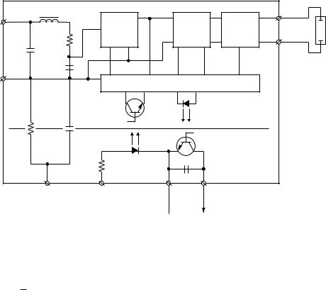
2.LAMP POWER SUPPLY CIRCUIT (LAMP DRIVER)
2-1. Configuration
The lamp power supply cicrcuit receives a DC220 to 390V (primary side) from the system power supply and provides a AC voltage (70 to 100VAC at ever turning on the lamp) to turn on the lamp. Fig. 2-1-1 shows the block diagram.
|
|
Lamp Driver |
|
|
|
|
L1 |
|
|
|
L1 |
|
|
Stabilizer |
Commu- |
Igniter |
|
|
|
tator |
|||
Power input |
R1 |
|
L2 |
||
|
|
|
|||
C1 |
|
|
|
|
|
|
|
|
|
|
|
|
C2 |
|
|
|
Lamp |
|
|
|
|
|
|
|
|
|
Control |
|
|
|
|
I122 |
|
|
Mains |
|
Rs |
|
I121 |
isolated |
|
|
Cs |
|
|
|
|
|
|
1K |
100nF |
|
|
|
|
|
|
|
|
|
CB3 |
CB2-1 |
CB2-2 |
|
|
|
EMC GND |
SCI |
|
|
|
|
(optional) |
|
|
|
|
|
|
|
Common |
Flag |
|
Fig. 2-1-1
The DC voltage is supplied to CB1 from the main power supply unit through an interlock switch. This voltage
becomes AC input x 2Ö2 (= 340V for AC120V input) when the lamp is off. CB2 is a connector for the lamp on control signal input (SCI) and lamp off control signal output (FLAG). When +5V is applied to SCI (CB2-1) in the standby on, I122 FET transistor turns on, the igniter develops a high voltage pulse (5 to 25 kV), and the lamp starts to light up.
The pulse normally continues to be developed until the lamp turns on (for max. 3s.). But if the lamp does not turn on, I121 does not turn on, the voltage of CB2-3 develops high. I121 turns on and develops low after the lamp turned on, the igniter circuit stops the operation. Then the AC70 to 100V is applied to the lamp.
2-1
3. OPTICAL SYSTEM
3-1. Configuration
|
No. |
Name |
Description |
|
|
|
|
Light source of the optical system. AC lighting system 120W, arc length 1.3 mm. |
|
|
1 |
UHP lamp |
As the arc length is shorter than the conventional metal halide lamp, the light source |
|
Lamp |
operates as an ideal light point source and this improves the light convergence factor. |
|||
|
|
Also, the color temperature gets higher and this allows to reproduce more natural |
||
unit |
|
|
||
|
|
white color. |
||
|
|
|
||
|
2 |
Parabolic |
Parabolic reflector converges light emitted from the UHP lamp forward in approximate |
|
|
reflector |
parallel light beams and illuminates the liquid crystal panel. |
||
|
|
|||
|
3 |
UV IR filter |
Optical filter to pass necessary visible rays and cut unnecessary ultraviolet rays and |
|
|
|
infrared rays among light emitted from the UHP lamp. |
||
|
|
|
||
|
4 |
Multi-lenses |
Two multi-lenses A and B allow a circular beam light emitted from the light source to |
|
|
illuminate the square liquid crystal panel evenly, thus providing projected pictures |
|||
|
A, B |
|||
|
|
with less brightness variation. |
||
|
|
|
||
|
5 |
Polarization |
Separates the illuminating light from the light source into P polarization light and S |
|
|
light beam |
|||
|
polarization light and leads both light to the multi-lens B with a little angle. |
|||
|
|
splitter (PBS) |
||
|
|
|
||
|
6 |
Phase |
Converts the polarization direction of incident light via the multi-lens B into another |
|
|
difference |
direction. Here, P polarization light waveform separated by PBS is converted into |
||
|
|
plate |
another S polarization light waveform. |
|
|
7 |
Condenser |
Converges the illuminating light emitted from the light source into the liquid crystal |
|
|
lens |
panel. |
||
|
|
|||
|
|
Dichroic |
Separates the white light emitted from the light source into RGB three primary colors. |
|
|
8 |
The white light emitted from the light source reflects B light using a dichroic mirror 1 |
||
|
mirror |
and the RG lights pass through the dichroic mirror 1. Of the RG lights passed, G light |
||
|
|
|||
Mirror |
|
|
is reflected by the dichroic mirror 2 and R light passes. |
|
box |
9 |
Full reflection |
Reflection mirror to lead the R and B lights separated by the dichroic mirrors 1 and 2 |
|
unit |
mirror |
to the liquid crystal panel. |
||
|
||||
|
10 |
Field lens |
Light transmitted through liquid crystal panel is converged in direction of focal point |
|
|
and effectively entered entrance pupil of the projection lens. |
|||
|
|
|
||
|
|
|
In the R axis optical path which is longer than those of G, B, the relay lens works as |
|
|
11 |
Relay lens |
a correction lens to arrange the illumination distribution of the liquid crystal panel |
|
|
|
|
surface with that of other liquid crystal panel. |
|
|
|
|
The illumination lights separated into RGB have the S polarizing waveform compo- |
|
|
|
|
nent in processing the PBS and phase difference plate operation previously de- |
|
|
|
|
scribed. |
|
|
|
Incident side |
The incident side polarized plate arranges the illumination light more effective direct |
|
|
|
polarizing waveform. The phase difference plate used works to converge the S |
||
|
12 |
polarized |
polarizing waveform into the P polarizing waveform which fits to the transparent axis |
|
|
plate/Phase |
of the liquid crystal panel. |
||
|
|
difference |
Since the phase difference plate possesses the wavelength characteristics for light, |
|
|
|
plate |
each RGB axis employs exclusive phase difference plate. These polarizing plates |
|
|
|
|
and difference plates are constructed in one plate by attaching each other, and put |
|
|
|
|
on a glass plate. |
|
|
|
|
To increase the color purity ratio of three primary colors, the glass plate possess the |
|
|
|
|
dichroic filter characteristics for RG axis. |
|
|
|
|
Light exit side polarized plate is put on the light exit plane. When no signal voltage is |
|
|
|
|
applied, the polarization direction of transmission light rotates by 90 degrees. When a |
|
|
|
|
voltage is applied, the polarization direction is controlled owing to the voltage |
|
|
|
Liquid crystal |
applied. That is, the liquid crystal panel employs such general TN type liquid crystal. |
|
Prism |
13 |
In this model, the incidence/exit polarization plate is placed (in normally white mode) |
||
panel |
so that the light transmission amount becomes maximum (white) when no voltage is |
|||
unit |
|
|||
|
|
added and the light transmission amount becomes minimum (black) when maximum |
||
|
|
|
||
|
|
|
voltage is added. |
|
|
|
|
According to the liquid crystal panel specification, exclusive panel for each RGB axis |
|
|
|
|
is employed and shown by identification seals. |
|
|
14 |
Cross prism |
Works to mix RGB lights passed through the liquid crystal panel. |
|
|
|
|
Demodulated by the video signal on the liquid crystal panel and projects pictures |
|
|
|
|
displayed on the liquid crystal at a screen. Light axis of the projection lens is set at |
|
Projec- |
|
Projection |
upper side of center of the liquid crystal panel and this realizes easy viewing of the |
|
15 |
panel because the projected screen position is upper than the unit position. The |
|||
tion |
||||
lens |
projected light shows S polarizing waveform and is compatible with the polarizing |
|||
lens |
|
|||
|
|
screen. |
||
|
|
|
||
|
|
|
The projection lens employs the zoom & focus system and allows to project enlarging |
|
|
|
|
a picture upto maximum approx. 300 inch. |
|
|
|
|
|
3-1

|
15 |
|
|
|
XGA 1.3 inch 3 plates system |
|
|
|
14 |
|
|
|
|
|
|
|
-3 |
|
|
10 |
|
1 |
|
9 |
|
|
|
9 |
UHP |
(120W) |
|
|
|
|
12 |
|
|||
|
|
|
|
|
|
||
|
13 |
|
|
-1 |
|
|
|
|
|
|
|
|
2 |
||
|
|
|
|
|
|
||
|
|
|
|
|
|
|
|
|
|
10 |
|
|
|
|
3 |
|
|
|
|
|
13 |
|
|
|
|
12 |
13 |
|
|
|
4 |
|
|
|
|
|
|
|
|
|
|
|
10 |
|
|
|
A |
|
|
|
|
|
|
|
|
|
|
|
|
|
|
|
5 |
|
9 |
|
|
|
|
|
|
|
-2 |
|
8 |
-2 |
6 |
4 |
|
|
|
|
|
||||
|
|
|
|
|
|
B |
|
|
11 |
|
8 |
-1 |
7 |
|
|
|
|
|
|
|
|
||
|
|
|
Fig. 3-1-1 |
Optical configuration diagram |
|
|
|
3-2
4. R.G.B. DRIVE CIRCUIT
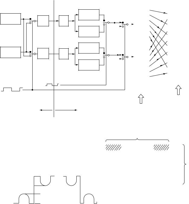
4-1. Outline
The outline of RGB drive circuit is described below
using the G process of the RGB drive circuit as an
example.
|
|
|
|
Q505,Q506,Q507 |
|
|
|
SW1 |
|
Q502 |
Normal |
|
Q514 |
Odd number |
|
|
amp.1 |
|
||
1 |
|
|
1 |
|||
|
|
|
SW3 |
|||
pixel memory |
DAC1 |
Amp. |
|
|||
|
|
|
|
|||
|
2 |
|
|
Q508,Q509,Q510 |
2 |
|
|
|
|
|
|
||
|
|
|
|
Inverted |
|
|
|
|
|
|
|
|
|
|
|
|
|
amp.1 |
|
|
|
|
|
|
Q511,Q512,Q513 |
|
|
|
1 |
|
Q504 |
Normal |
|
|
Even number |
DAC2 |
|
amp.2 |
1 |
Q514 |
|
|
Amp. |
|
||||
pixel memory |
|
Q523,Q524,Q510 |
|
|||
|
2 |
|
|
2 |
SW4 |
|
|
|
|
|
|||
|
SW2 |
|
|
Inverted |
|
|
|
|
|
|
|
||
|
|
|
|
|
|
|
|
|
|
|
amp.2 |
|
|
|
|
|
Line inverted |
|
|
|
Frame inverted |
|
|
|
|
|
|
Digital PC board |
|
|
Drive PC board |
|
||
|
Exclusive for odd number pixel |
|
|
|||||||||
|
|
|
|
|
Q516 |
|
Panel |
|||||
|
|
|
|
|
Samplehold |
& |
decompositePhase- |
|
|
VIDEO |
5 |
|
|
|
Q515 |
|
|
|
|
|
|
input |
2 |
|
|
|
1SW5 |
|
|
|
|
|
|
|
|
|
||
|
|
|
|
|
|
|
|
|
|
|
3 |
|
|
2 |
|
|
|
|
|
|
|
|
4 |
|
|
|
|
|
|
|
|
1 |
6 |
|
|
|
6 |
|
|
|
|
|
|
|
|
|
|
|
|
||
|
|
|
|
|
|
|
|
|
|
|
7 |
|
|
|
|
|
|
holdSample |
|
decompositePhase |
|
|
|
|
|
|
1 Q515 |
|
& |
|
|
|
8 |
|
||||
|
|
|
|
|
|
|
|
|
||||
|
|
|
|
|
|
|
|
9 |
|
|||
|
|
|
|
|
|
|
|
|
|
|
|
|
|
|
2 SW6 |
|
|
|
|
|
|
|
|||
|
|
|
|
|
|
|
|
|
10 |
|
||
|
|
|
|
|
|
|
|
|
|
|
|
|
|
|
|
|
|
|
|
|
|
|
|
11 |
|
|
|
|
|
|
|
|
- |
|
|
|
12 |
|
|
|
|
|
|
|
2 |
6 |
|
|
|
|
|
|
|
|
|
|
|
|
|
|
|
|
|
|
|
|
|
|
|
Q517 |
|
|
|
|
|||
|
|
|
Exclusive for |
|
|
|
|
|||||
|
|
|
even number pixel |
|
|
|
|
|||||
|
|
|
|
|
|
|
|
|
12-phase composite |
|||
|
|
|
|
|
|
|
|
|
(12-phase collectively input) |
|||
|
|
12-phase decomposite |
|
|
|
|
||||||
Fig. 4-1-1
In the panel, 1024 pixels are arranged in a horizontal |
|
|
|
1024 pixels |
||||||||
direction and 768 lines of the pixels are in a vertical as |
1 |
2 |
3 |
1022 1023 1024 |
||||||||
shown in Fig. 4-1-2. |
|
|
|
|
||||||||
|
|
|
|
|
|
|
|
|
|
|
||
|
|
|
|
|
|
|
|
|
|
|
||
As an H inverted drive system is employed, the panel |
|
|
|
|
|
|
|
|||||
|
|
|
|
|
|
|
||||||
input signal waveform is as shown in Fig. 4-1-3. |
|
|
|
|
|
|
|
|||||
|
|
|
|
|
|
|
||||||
Black level |
|
|
|
|
|
|
|
|
|
|
|
|
|
|
|
|
|
|
|
|
|
|
|
||
|
|
|
|
|
|
|
|
|
|
|
||
|
|
|
|
|
|
|
|
|
|
|
||
White level |
2nd line |
|
1st line |
|
|
|
|
|
|
|
||
|
|
|
|
|
|
|
|
|||||
|
|
|
|
|
|
|
|
|||||
Center voltage |
|
|
|
|
|
|
|
|
|
|||
|
|
|
|
|
|
|
|
|
|
|
|
|
|
|
|
2nd line |
|
|
|
|
|
|
|
||
1st line |
White level |
|
|
|
|
Fig. 4-1-2 |
||||||
|
|
|
|
|
|
|||||||
|
|
|
|
|
|
|
|
|
||||
|
|
Black level |
|
|
|
|
|
|
|
|
|
|
|
1st frame |
|
2nd frame |
|
|
|
|
|
|
|
||
1st line
768 lines
768th line
Fig. 4-1-3
4-1

The signal as shown in Fig. 4-1-1 is separated into the odd and even pixels at the digital PC board. After the signal process is carried out in the drive PC board, the odd and even pixel signals are synthesized to decomposite the signal on the panel.
Referring to Fig. 4-1-1, the operation principle is described.
When assuming;
1)the signal passing through DAC1 ® Q502 ® Normal amp. 1 ® SW31 ® SW5 ® Q516 to the positive phase 1,
2)the signal passing through DAC1 ® Q502 ® inverted amp. 1 ® SW32 ® SW5 ® Q516 to the inverted phase 1,
<1st frame>
3)the signal passing through DAC2 ® Q504 ® Normal amp. 1 ® SW41 ® SW6 ® Q517 to the positive phase 2 and
4)the signal passing through DAC2 ® Q504 ® inverted
amp. 2 ® SW42 ® SW6 ® Q517 to inverted phase 2,
the AC and DC levels of the positive phases 1, 2 and the inverted phases 1, 2 are expected to be the same.
However, each voltage will vary slightly owing to the adjustment variation. In this case, each frame signal is assumed as follows.
1 |
2 |
3 |
4 |
5 |
6 |
7 |
8 |
9 |
10 |
11 |
12 |
Pixel |
Inverted phase 2 voltage
|
|
|
|
|
|
|
|
|
|
Inverted phase |
|
|
|
|
|
|
|
|
|||
|
|
|
|
|
|
|
|
|
|
|
|
|
|
|
|
|
|
||||
|
|
|
|
|
|
|
|
|
|
1 voltage |
|
|
|
|
2nd line |
|
|||||
|
|
|
|
|
|
|
|
|
|
|
|
|
|
|
|
|
|
|
|||
Center voltage |
|
|
|
|
|
|
|
|
|
|
|
|
|
|
|
|
|
|
|
|
|
|
|
|
|
|
|
|
|
|
|
|
|
|
|
|
|
|
|
|
|
|
|
1 |
2 |
3 |
4 |
5 |
6 |
7 |
8 |
9 |
10 11 12 Pixel |
|
|
|
|
|
|
|
|
||||
Normal phase 1 |
|
|
|
|
|
|
|
|
|
|
|
|
|
|
|
|
|
|
|
|
|
|
|
|
|
|
|
|
|
|
|
|
|
|
|
|
|
|
|
|
|
|
|
voltage |
|
|
|
|
|
|
|
|
|
|
|
|
|
|
|
|
|
|
|
|
|
Normal phase 2 |
|
|
|
|
|
|
|
|
|
|
|
|
|
|
|
|
|
|
|
|
|
|
|
|
1st line |
|
|
|
|
|
|
|
|
|
|
|
|
|
|
||||
voltage |
|
|
|
|
|
|
|
|
|
|
|
|
|
|
|
|
|
||||
<2nd line>
1 |
2 |
3 |
4 |
5 |
6 |
7 |
8 |
9 |
10 |
11 |
12 Pixel |
|||
Inverted phase 2 |
|
|
|
|
|
|
|
|
|
|
|
|
|
|
voltage |
|
|
|
|
|
|
|
|
|
|
|
|
||
Inverted phase 1 |
|
|
|
|
|
|
|
|
|
|
|
|
||
|
|
|
|
|
|
|
|
|
|
|
|
|||
voltage |
|
|
|
|
|
|
|
|
|
|
|
|
||
Center voltage |
|
|
|
|
|
|
|
|
|
|
|
|
2nd line |
|
|
|
|
|
|
|
|
|
|
|
|
|
|
||
|
|
|
|
|
|
|
|
|
|
|
|
|
||
1st line
1 |
2 |
3 |
4 |
5 |
6 |
7 |
8 |
9 |
10 |
11 |
12 |
Pixel |
Normal phase 1 voltage
Normal phase 2 voltage
Fig. 4-1-4
As shown in Fig. 4-1-4, even if a slight level difference occurs among the positive phases 1, 2 and inverted phases 1, 2 signals (approx. 100 mV), the level difference will be decreased visually by reducing the level
variation of the same line between each frame and inverting the pixel voltage of the adjacent lines (1st line and 2nd line) between each frame.
4-2
4-2. Operation Description
The video signal of the odd number pixel (even number pixel) is sent to Q501 (Q503) base and supplied to pin 16 of Q502 (Q504), LM1201M. The signal is clamped at pin 16 and the pedestal voltage is adjusted at pin 6 after the DC level is stabilized and then AC level is adjusted at pin 3.
The signal is developed from pin 8, supplied to the buffer circuits of Q505 – Q507 and Q511 – Q513, and supplied to the inverted circuits of Q508, Q509, Q510, Q523, Q525 and Q510. These signals are supplied to pins 5, 6, 8, 13, 15 and 16 of 12 phases development IC. CXA2504N, Q516 and Q517 of sample-and-hold passing through the SW circuit composed of Q514 and Q515. The signals are developed from pins 37, 35, 33, 25 and 23 for each input.
The signals at pins 4, 7, 14 are used as bias input and the bias inputs set the center DC voltage of output equal to the bias voltage.
Q519 works to suppress the noise occurred at 12 phases collective input process of the panel.
4-2-2. Basic Component
4-2-1. Outline of Liquid Crystal Panel
The liquid crystal panel module is an active matrix panel with a built-in driver of multi-crystal silicon. The liquid crystal panel module is designed for use of color projectors in combination with an enlargement projection system and dichroic mirror.
<Basic specification>
(1) |
Screen size |
26.624 (W) x 19.968 (H) |
(2) |
Pixel number |
1024 (W) x 768 (H) |
(3)Applicable to XGA
(4)Monochrome panel
(5) |
Drive system |
H inverted drive |
(6) |
Dot clock |
65 MHz |
(7)Inverted function for UP/DOWN/LEFT/RIGHT directions
Table 4-2-1 Terminal description
Pin No. |
Name |
Pin No. |
Name |
Pin No. |
Name |
Pin No. |
Name |
||||||||
1 |
|
DT |
10 |
|
VID7 |
19 |
|
|
28 |
VID10 |
|||||
|
|
|
DIRX |
|
|||||||||||
2 |
|
|
11 |
|
VID5 |
20 |
|
DIRX |
29 |
VID12 |
|||||
|
CLY |
|
|
|
|||||||||||
3 |
|
CLY |
12 |
|
VID3 |
21 |
ENB2 |
30 |
LCCOM |
||||||
4 |
VDDY |
13 |
|
VID1 |
22 |
ENB1 |
31 |
|
N.C. |
||||||
5 |
NRS2 |
14 |
VSSX |
23 |
VSSX |
32 |
|
NRG |
|||||||
6 |
NRS1 |
15 |
|
|
24 |
|
VID2 |
33 |
|
DY |
|||||
|
CLX |
|
|
|
|||||||||||
7 |
LCCOM |
16 |
|
CLX |
25 |
|
VID4 |
34 |
|
DIRY |
|||||
|
|
|
|
|
|
|
|
|
|
|
|
|
|
|
|
8 |
VID11 |
17 |
|
DX |
26 |
|
VID6 |
35 |
|
|
|||||
|
|
|
DIRY |
|
|||||||||||
9 |
VID9 |
18 |
VDDX |
27 |
|
VID8 |
36 |
VSSY |
|||||||
|
|
|
|
|
|
|
|
|
|
|
|
|
|
|
|
4-3
|
|
|
|
|
|
|
|
Table 4-2-2 Input terminal function description |
|
|
|
|
|
|
|
|
|
|
|
Name |
Function |
||||||||
DX |
Start pulse input terminal of X shift register composing X driver. |
||||||||
|
|
|
|
|
|
|
|||
CLX, |
CLX |
|
|
|
Transfer clock input terminal X shift register composing X driver |
||||
|
|
|
|
|
|||||
DIRX, |
DIRX |
|
|
X driver driving direction switch input terminal (DIRX = H R shift, DIRX = L L shift) |
|||||
ENB1 – ENB2 |
X driver enable pulse input terminal |
||||||||
VID1 – VID12 |
X driver video signal input terminal |
||||||||
|
|
|
|
|
|
|
|
|
|
DY |
Start pulse input terminal of Y shift register composing Y driver. |
||||||||
|
|
|
|
||||||
CLY, |
CLY |
|
|
Transfer clock input terminal of Y shift register composing Y driver. |
|||||
|
|
|
|
|
|
|
|
Transfer clock input terminal of Y shift register composing Y driver. (DIRX = H Down shift, |
|
DIRY, DIRY |
|||||||||
DIRX = L Up shift) |
|||||||||
|
|
|
|
|
|
|
|
||
LCCOM |
Diagonal electrode potential input terminal of liquid crystal panel |
||||||||
VDDX |
X driver positive power supply input terminal |
||||||||
VDDY |
Y driver positive power supply input terminal |
||||||||
VSSX |
X driver negative power supply input terminal |
||||||||
VSSY |
Y driver negative power supply input terminal |
||||||||
NRG |
Drive signal input terminal for auxiliary signal circuit |
||||||||
NRS1 – NRS2 |
Auxiliary signal input terminal |
||||||||
|
|
|
|
|
|
|
|
|
|
4-4
5. MICROPROCESSOR
5-1. System Outline
The system microprocessor has features as shown below.
In considering easy maintenance for specification modification, etc., the program content is written in the built-in non-volatile memory.
The program is also developed in considering use of structured notation, parts modularity, and multi filling system.
Major functions of the system microprocessor are as follows.
5-1-1. System Control
•Microprocessor program write process
•Non-volatile memory control process
•Remote control reception process
•RS-232C transmission/reception process
•Status read process
•On-screen display process
5-1-2. Normal Control |
|
|
• |
Power |
ON/OFF |
|
|
(Main/Fan/Lamp) |
• |
Input switch |
(RGB/Video/Camera) |
• |
Sound volume control |
UP/DOWN |
•Menu
• |
Adjust |
(Up/Down/Left/Right) |
• |
All mute |
ON/OFF |
• |
Audio mute |
ON/OFF |
• |
Display |
ON/OFF |
• |
Freeze |
ON/OFF |
• |
Resize |
ON/OFF |
• |
Focus |
UP/DOWN |
|
|
(at camera use) |
• |
Zoom |
UP/DOWN |
|
|
(at camera use) |
5-1-3. Adjustment Control
•Video controls (high & low brightness ratio, brightness, color density, tint, sharpness)
•Panel adjustments (V position, H position, phase, clock, user registration, user read-out)
•Mode adjustments (Wide, MIC, OSD mute, projection)
•Language adjustments (English, Japanese, French, German, Spanish, Italian)
5-1-4. Adjustment Control at Factory Delivery
•Video sub adjustments (RGB gain, sub-bright)
•Drive adjustments (each item for panel controls, RGB trimming)
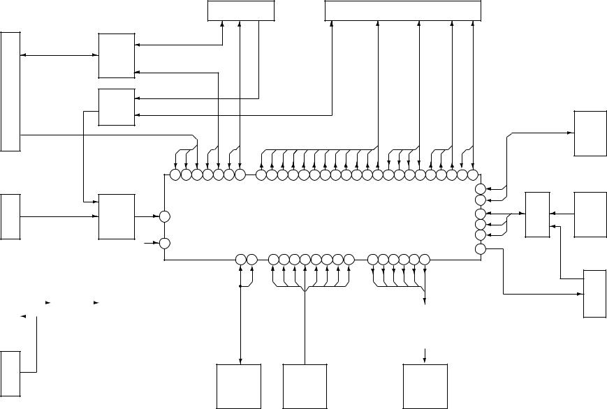
Fig. 5-1-1 shows the system block diagram.
5-1
PL001
HC125PL001
2 /
QL012
HC125
3
/
PL003 |
QL005 |
HC14
2-5
PL006 |
QL003 |
|
|
QL004 |
|
||
|
|
|
PQ20VZ1U |
|
|
RN5VD27A |
|
|
|
|
|
|
|
|
|
|
|
|
|
|
|
|
|
|
|
|
|
|
|
|
|
PL002
|
|
|
|
PL010 |
|
|
PL004 |
|
|
|
|
|
|
|
2 |
|
|
|
|
|
|
|
|
|
|
|
|
|
/ |
|
|
|
|
|
|
|
|
|
|
|
|
|
2 |
|
|
|
|
|
|
|
|
|
|
|
|
|
/ |
|
|
|
|
|
|
|
|
|
|
|
|
|
|
|
/ |
/ |
|
/12 |
/ |
4 |
/ |
/ |
|
|
DRIVE |
|
|
|
2 |
2 |
|
|
3 |
2 |
|
|
|
||
|
|
|
|
|
|
|
|
|
|
|
2 |
|
|
7 |
5 |
4 |
78 79 11 10 |
77 76 75 74 72 71 70 69 68 67 66 65 64 63 62 61 60 59 49 55 54 |
/ |
|
|
||||||
|
|
|
|||||||||||
|
|
|
|
|
|
|
|
|
|
58 |
|
QL010 |
|
|
|
|
|
|
|
|
|
|
|
|
|
|
|
|
|
|
|
|
|
|
|
|
|
57 |
3 |
HC165 |
|
|
|
|
|
|
|
|
|
|
|
53 |
5 |
|
|
19 |
|
|
|
|
QL002 |
|
|
|
|
/ |
/ |
SENSOR |
|
|
|
|
|
|
HD64F3337YF16 |
|
|
|
|
52 |
|
|
|
|
|
|
|
|
|
|
|
|
|
|
|
|
|
1 |
|
|
|
|
|
|
|
|
|
51 |
|
|
|
|
|
|
|
|
|
|
|
|
48 |
|
|
|
|
|
|
|
|
|
|
|
|
|
|
|
|
|
|
|
|
|
|
16 17 |
21 22 23 24 25 26 27 28 |
39 40 41 42 43 44 |
|
|
|
|
PL009 |
||
|
|
|
|
|
|
|
|
|
|
|
|
|
|
|
|
/6 |
|
|
|
|
|
|
|
2 |
8 |
HC541 |
|
|
/ |
/ |
|
|
|
|
|
|
QL007 |
|
|
|
|
|
|
|
|
/6 |
|
|
CAT24C16J
SW |
LED |
QL006
Fig. 5-1-1 System block diagram
5-2. System Microprocessor
The system microprocessor QL002 employs an 8 bit micro-controller (HD64F3337YF16).
In this system microprocessor, a program area is provided inside the non-volatile memory.
Using an exclusive data-writer allows easy maintenance of the system microprocessor when specification modification, bug correction, etc. will occur.
Table 5-2-1 shows the terminal functions of the system microprocessor.
Table 5-2-1 Terminal functions of the system microprocessor
Pin No. |
Name |
Function |
I/O |
Pin No. |
Name |
Function |
I/O |
1 |
RES |
Reset input |
I |
41 |
LED2 |
LED data 2 |
O |
2 |
XTAL |
Clock input for oscillation |
I |
42 |
LED3 |
LED data 3 |
O |
3 |
EXTAL |
Clock output for oscillation |
O |
43 |
LED4 |
LED data 4 |
O |
4 |
MD1 |
Mode 1 |
I |
44 |
LED5 |
LED data 5 |
O |
5 |
MD0 |
Mode 2 |
I |
45 |
MAIN. PW |
Main power supply swtich |
O |
6 |
NMI |
Priority interruption |
I |
46 |
FAN. PW |
Fan power supply switch |
O |
7 |
FVPF |
Memory write voltage |
I |
47 |
VCC2 |
Digital power supply |
I |
8 |
VCC1 |
Digital power supply |
I |
48 |
LAMP. PW |
Lamp power supply switch |
O |
9 |
WDT |
Not used |
O |
49 |
OSDL |
OSD load |
O |
10 |
RXD0 |
RS-232C reception for camera |
I |
50 |
DDCV |
Not used |
I |
11 |
TXD0 |
RS-232C transfer for camera |
O |
51 |
SENL |
Sensor load |
O |
12 |
GND1 |
Digital ground |
I |
52 |
SENC |
Used for sensor |
O |
13 |
SDA |
Not used |
I/O |
53 |
SEND |
Used for sensor |
I |
14 |
f |
Oscillation clock |
O |
54 |
VD0C |
Video I2C clock |
O |
15 |
SEL |
Remote controller selection |
O |
55 |
VD0D |
Video I2C data |
I/O |
16 |
EEPCK |
Non-volatile memory clock |
O |
56 |
GND2 |
Digital ground |
I |
17 |
EEPDT |
Non-volatile memory data |
I/O |
57 |
DRVC |
Drive I2C clock |
O |
18 |
VD |
Not used |
I |
58 |
DRVD |
Drive I2C data |
O |
19 |
REMOCON |
Remote controller reception |
I |
59 |
OSDC |
OSD clock |
O |
20 |
AUX |
Not used |
O |
60 |
OSDD |
OSD data |
O |
21 |
KEY0 |
Key input 0 |
I |
61 |
PLLU |
PLL enable |
O |
22 |
KEY1 |
Key input 1 |
I |
62 |
SYGL |
SYG load |
O |
23 |
KEY2 |
Key input 2 |
I |
63 |
SYGC |
SYG clock |
O |
24 |
KEY3 |
Key input 3 |
I |
64 |
SYGD |
SYG data |
I/O |
25 |
KEY4 |
Key input 4 |
I |
65 |
D0 |
T-FORC data 0 |
O |
26 |
KEY5 |
Key input 5 |
I |
66 |
D1 |
T-FORC data 1 |
O |
27 |
KEY6 |
Key input 6 |
I |
67 |
D2 |
T-FORC data 2 |
O |
28 |
KEY7 |
Key input 7 |
I |
68 |
D3 |
T-FORC data 3 |
O |
29 |
AVCC |
Analog power supply |
I |
69 |
D4 |
T-FORC data 4 |
O |
30 |
AD0 |
Not used |
I |
70 |
D5 |
T-FORC data 5 |
O |
31 |
AD1 |
Not used |
I |
71 |
D6 |
T-FORC data 6 |
O |
32 |
AD2 |
Not used |
I |
72 |
D7 |
T-FORC data 7 |
O |
33 |
AD3 |
Not used |
I |
73 |
GND3 |
Digital ground |
I |
34 |
AD4 |
Not used |
I |
74 |
CLK |
T-FORC clock |
O |
35 |
AD5 |
Not used |
I |
75 |
R/W |
T-FORC read/write |
O |
36 |
AD6 |
Not used |
I |
76 |
ENB |
T-FORC enable |
O |
37 |
AD7 |
Not used |
I |
77 |
RST |
T-FORC reset |
O |
38 |
AGND |
Analog ground |
I |
78 |
TXD1 |
RS-232C transfer for control |
O |
39 |
LED0 |
LED data 0 |
O |
79 |
RXD1 |
RS-232C reception for control |
I |
40 |
LED1 |
LED data 1 |
O |
80 |
SCL |
Not used |
O |
5-3
5-3. Power Supply Reset Process
In the power supply reset process, power supply reset IC (RN5VD27A), QL004 is employed.
The reset IC,QL004, develops the reset signal when the power supply voltage for the microprocessor varies and becomes lower than the specified voltage, and sends the signal to the reset terminal of the system microprocessor (QL002).
5-4. Non-volatile Memory Control Process
In the non-volatile memory process, data reading and saving for various adjustments are carried out on the non-volatile memory, QL006 (CAT24C16J).
When the power (AC) is on, all the adjustment data are read out by the system microprocessor (QL002), then the previous status is realized.
When saving the data, all the adjustment data are written by the system microprocessor (QL002), then the current status is preserved.
However, if a failure (such as power interruption due to lightning, etc.) occurs during the adjustment data writing, a data error may occur. If the data is determined as incorrect, the initial data memorized on the system microprocessor (QL002) is read out and stored on the non-volatile memory.
5-5. Remote Control Reception Process
In the remote control reception process, a remote control unit (CT-9925) connected to the remote control terminal emits a remote control signal and a remote control signal receive section on the front panel, the rear panel or the camera arm (for TLP511) decodes the signal.
The remote control signals for rear panel and camera section (for TLP511) are selected by QL012 buffer (TC74HC125AF). Then both signals are mixed with the remote control signal for front panel through QL005 buffer (74HC14AF).
Finally, the signal mixed is supplied to the remote control terminal of the system microprocessor (QL002).
5-6. RS-232C Transmission/Reception
Process
In the RS-232C transmission/reception process, an RS232C signal entered through the RS-232C connector (D- SUB 9P) is decoded in the RS-232C interface (mPD4721), and fed to RXD1 terminal of the system microprocessor (QL002).
In the RS-232C transmission process, RS-232C signal developed from TXD0 terminal of the system microprocessor (QL002) is decoded in the RS-232C interface (mPD4721) and fed to the camera microprocessor section.
|
|
|
|
|
5-7. Status Read Process |
|
|
|||
|
|
|
|
|
In the status read process, the following status shown in |
|||||
|
|
|
|
|
the table below are read by QL010 (74HC165AF) and |
|||||
|
|
|
|
|
the error process corresponding to each status is carried |
|||||
|
|
|
|
|
out. |
|
|
|
|
|
|
|
|
|
|
Table 5-7-1 shows the contents of the status read signals |
|||||
|
|
|
|
|
and the logic. |
|
|
|
|
|
|
Table 5-7-1 The contents of the status read signals and the logic |
|
|
|||||||
|
|
|
|
|
|
|
|
|
|
|
Signal name |
A |
B |
C |
D |
|
E |
F |
|
G |
H |
Pin No. |
11 |
12 |
13 |
14 |
|
3 |
4 |
|
5 |
6 |
QL010 |
FAN1. ER |
FAN1. SW |
FAN2. ER |
|
|
TEMP1. ER |
|
|
LAMP. ER |
MAIN. ER |
(L) |
Abnormal |
Normal |
Abnormal |
|
|
Normal |
|
|
Abnormal |
Abnormal |
(H) |
Normal |
Abnormal |
Normal |
|
|
Abnormal |
|
|
Normal |
Normal |
|
|
|
|
|
|
|
|
|
|
|
5-4
Loading...