


EM1-33039E
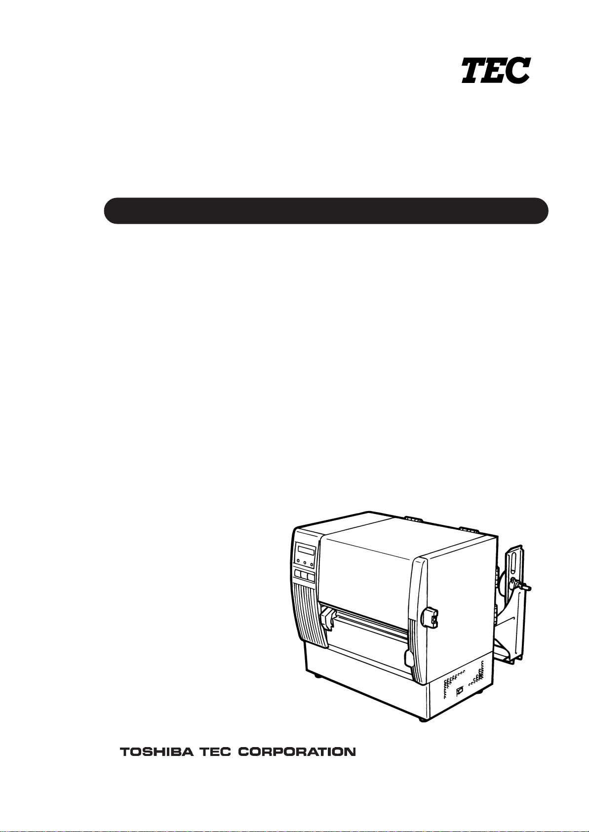
TEC Thermal Printer
B-870 SERIES
Owner’s Manual
Table of Contents
Copyright © 2002
by TOSHIBA TEC CORPORATION
All Rights Reserved
570 Ohito, Ohito-cho, Tagata-gun, Shizuoka-ken, JAPAN
This equipment has been tested and found to comply with the limits for a Class A digital device,
pursuant to Part 15 of the FCC Rules. These limits are designed to provide reasonable protection
against harmful interference when the equipment is operated in a commercial environment. This
equipment generates, uses, and can radiate radio frequency energy and, if not installed and used in
accordance with the instruction manual, may cause harmful interference to radio communications.
Operations of this equipment in a residential area is likely to cause harmful interference in which case
the user will be required to correct the interference at his own expense. (for USA only)
"This Class A digital apparatus meets all requirements of the Canadian Interference-Causing
Equipment Regulations."
"Cet appareil numérique de la classe A respecte toutes les exigences du Règlement sur le matériel
brouilleur de Canada."
(for CANADA only)
Changes or modifications not expressly approved by manufacturer for compliance could void the
user's authority to operate the equipment.
WARNING!
This is a Class A product. In a domestic environment this product may cause radio interference in
which case the user may be required to take adequate measures.
CAUTION:
Do not touch moving parts. To reduce the risk that fingers, jewelry, clothing, etc., be drawn into the
moving parts, push the switch in the "OFF" position to stop movement.
As an ENERGY STAR
®
Partner, TOSHIBA TEC has determined that
this product meets the
ENERGY STAR
®
guidelines for energy efficiency.
-- Outline of the International ENERGY STAR
®
Office Equipment Program --
The International
ENERGY STAR
®
Office Equipment Program is an international program that
promotes energy saving through the penetration of energy efficient computers and other office
equipment. The program backs the development and dissemination of products with functions that
effectively reduce energy consumption. It is an open system in which business proprietors can
participate voluntarily. The targeted products are office equipment such as computers, monitors,
printers, facsimiles, copiers, scanners, and multifunction devices. Their standards and logos are
uniform among participating nations.
ENERGY STAR is a U.S. registered mark.
(i)
Safety Summary
EM1-33039E
Safety Summary
Personal safety in handling or maintaining the equipment is extremely important. Warnings and Cautions
necessary for safe handling are included in this manual. All warnings and cautions contained in this
manual should be read and understood before handling or maintaining the equipment.
Do not attempt to effect repairs or modifications to this equipment. If a fault occurs that cannot be rectified
using the procedures described in this manual, turn off the power, unplug the machine, then contact your
authorized TOSHIBA TEC representative for assistance.
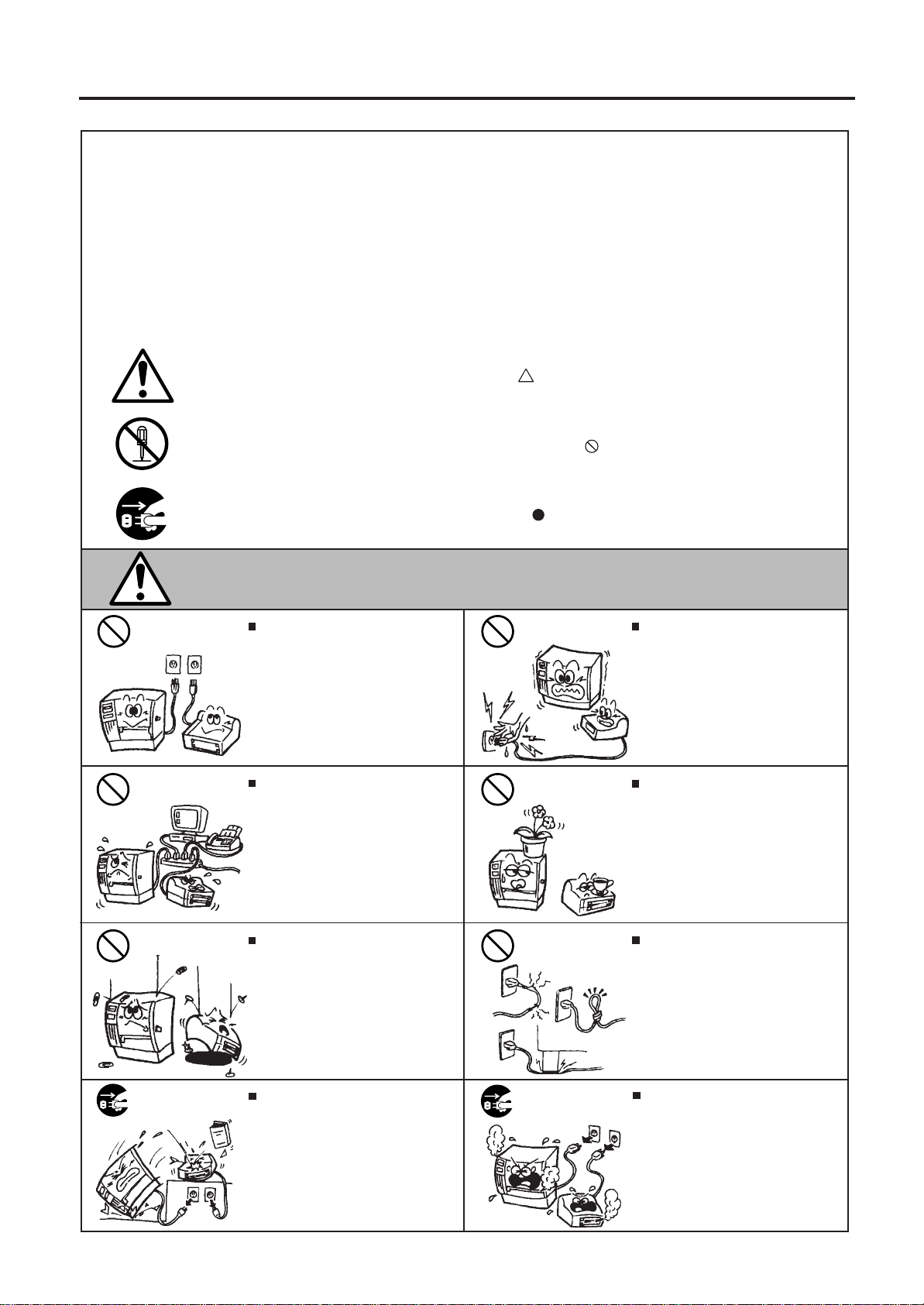
Meanings of Each Symbol
This symbol indicates warning items (including cautions).
Specific warning contents are drawn inside the symbol.
(The symbol on the left indicates a general caution.)
This symbol indicates prohibited actions (prohibited items).
Specific prohibited contents are drawn inside or near the symbol.
(The symbol on the left indicates “no disassembling”.)
This symbol indicates actions which must be performed.
Specific instructions are drawn inside or near the symbol.
(The symbol on the left indicates “disconnect the power cord plug from the outlet”.)
Do not use voltages other than the
voltage (AC) specified on the rating
plate, as this may cause fire or
electric shock.
Any other than the
specified AC voltage
is prohibited.
WARNING
This indicates that there is the risk of death or serious injury if the
machines are improperly handled contrary to this indication.
Prohibited
Do not plug in or unplug the power
cord plug with wet hands as this may
cause electric shock.
Do not place metal objects or
water-filled containers such as flower
vases, flower pots or mugs, etc. on
top of the machines. If metal objects
or spilled liquid enter the machines,
this may cause fire or electric
shock.
If the machines share the same
outlet with any other electrical
appliances which consume large
amounts of power, the voltage will
fluctuate widely each time these
appliances operate. Be sure to
provide an exclusive outlet for the
machine as this may cause the
machines to malfunction.
Do not insert or drop metal,
flammable or other foreign objects into
the machines through the ventilation
slits, as this may cause fire or electric
shock.
Prohibited
Prohibited
Prohibited
Do not scratch, damage or modify
the power cords. Also, do not place
heavy objects on, pull on, or exces-
sively bend the cords, as this may
cause fire or electrical shock.
Prohibited
Continued use of the machines in an
abnormal condition such as when the
machines are producing smoke or
strange smells may cause fire or elec-
tric shock. In these cases, immedi-
ately turn off the power switches and
disconnect the power cord plugs from
the outlet. Then, contact your author-
ized TOSHIBA TEC representative for
assistance.
Disconnect
the plug.
If the machines are dropped or their
cabinets damaged, first turn off the
power switches and disconnect the
power cord plugs from the outlet, and
then contact your authorized
TOSHIBA TEC representative for
assistance. Continued use of the
machine in that condition may cause
fire or electric shock.
Disconnect
the plug.
(ii)
Safety Summary
EM1-33039E
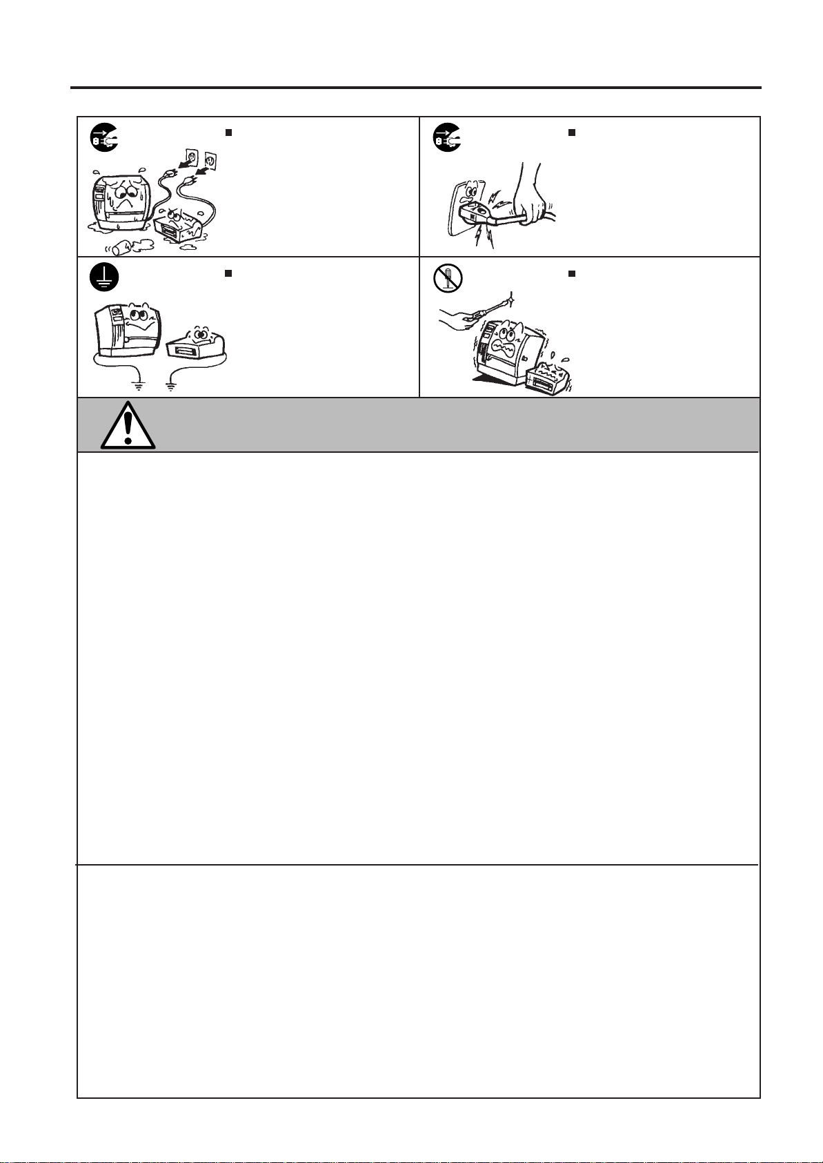
CAUTION
This indicates that there is the risk of personal Injury or damage to
objects if the machines are improperly handled contrary to this indication.
If foreign objects (metal fragments,
water, liquids) enter the machines,
first turn off the power switches and
disconnect the power cord plugs from
the outlet, and then contact your
authorized TOSHIBA TEC repre-
sentative for assistance. Continued
use of the machine in that condition
may cause fire or electric shock.
Disconnect
the plug.
Do not remove covers, repair or
modify the machine by yourself. You
may be injured by high voltage, very
hot parts or sharp edges inside the
machine.
No disassem-
bling.
Ensure that the equipment is
properly grounded. Extension cables
should also be grounded. Fire or
electric shock could occur on
improperly grounded equipment.
Connect a
grounding
wire.
When unplugging the power cords,
be sure to hold and pull on the plug
portion. Pulling on the cord portion
may cut or expose the internal wires
and cause fire or electric shock.
Disconnect
the plug.
Precautions
The following precautions will help to ensure that this machine will continue to function correctly.
• Try to avoid locations that have the following adverse conditions:
* Temperatures out of the specification * Direct sunlight * High humidity
* Shared power source * Excessive vibration * Dust/Gas
• The cover should be cleaned by wiping with a dry cloth or a cloth slightly dampened with a mild
detergent solution. NEVER USE THINNER OR ANY OTHER VOLATILE SOLVENT on the plastic
covers.
• USE ONLY TOSHIBA TEC SPECIFIED paper and ribbons.
• DO NOT STORE the paper or ribbons where they might be exposed to direct sunlight, high tem-
peratures, high humidity, dust, or gas.
• Ensure the printer is operated on a level surface.
• Any data stored in the memory of the printer could be lost during a printer fault.
• Try to avoid using this equipment on the same power supply as high voltage equipment or equip-
ment likely to cause mains interference.
• Unplug the machine whenever you are working inside it or cleaning it.
• Keep your work environment static free.
• Do not place heavy objects on top of the machines, as these items may become unbalanced and fall
causing injury.
• Do not block the ventilation slits of the machines, as this will cause heat to build up inside the
machines and may cause fire.
• Do not lean against the machine. It may fall on you and could cause injury.
• Care must be taken not to injure yourself with the printer paper cutter.
• Unplug the machine when it is not used for a long period of time.
Request Regarding Maintenance
• Utilize our maintenance services.
After purchasing the machine, contact your authorized TOSHIBA TEC representative for assistance
once a year to have the inside of the machine cleaned. Otherwise, dust will build up inside the
machines and may cause a fire or a malfunction. Cleaning is particularly effective before humid
rainy seasons.
• Our preventive maintenance service performs the periodic checks and other work required to
maintain the quality and performance of the machines, preventing accidents beforehand.
For details, please consult your authorized TOSHIBA TEC representative for assistance.
• Using insecticides and other chemicals
Do not expose the machines to insecticides or other volatile solvents. This will cause the cabinet or
other parts to deteriorate or cause the paint to peel.

TABLE OF CONTENTS
1.INTRODUCTION................................................................................................1- 1
1.1APPLICABLE MODEL................................................................................1- 1
1.2ACCESSORIES..........................................................................................1- 1
2.SPECIFICATIONS..............................................................................................2- 1
2.1PRINTER....................................................................................................2- 1
2.2OPTIONS....................................................................................................2- 2
2.3MEDIA.........................................................................................................2- 3
2.4RIBBON......................................................................................................2- 3
3.OVERVIEW........................................................................................................3- 1
3.1FRONT/REAR VIEW...................................................................................3- 1
3.2OPERATION PANEL..................................................................................3- 1
4.DIP SWITCH FUNCTIONS.................................................................................4- 1
5.SET UP PROCEDURE.......................................................................................5- 1
5.1REQUIREMENTS FOR OPERATION........................................................5- 1
5.2SETTING UP THE PRINTER......................................................................5- 1
6.INSTALLING THE PRINTER..............................................................................6- 1
6.1CONNECTING THE POWER CORD AND CABLES..................................6- 1
6.2HOLDER STAND INSTALLATION.............................................................6- 1
7.LOADING THE RIBBON.....................................................................................7- 1
8.LOADING THE MEDIA.......................................................................................8- 1
9.INSERTING THE OPTIONAL FLASH MEMORY CARD....................................9- 1
10.CARE/HANDLING OF THE MEDIA AND RIBBON..........................................10- 1
11.GENERAL MAINTENANCE.............................................................................11- 1
11.1CLEANING...............................................................................................11- 1
11.2UNDER THE MEDIA GUIDES..................................................................11- 3
11.3COVERS AND PANELS...........................................................................11- 3
11.4REMOVING JAMMED MEDIA..................................................................11- 4
11.5THRESHOLD SETTING...........................................................................11- 6
12.TROUBLESHOOTING......................................................................................12- 1
Page
EM1-33039E
CAUTION:
1. This manual may not be copied in whole or in part without prior written permission of
TOSHIBA TEC.
2. The contents of this manual may be changed without notification.
3. Please refer to your local Authorized Service representative with regard to any queries
you may have in this manual.
1-1
1. INTRODUCTION
EM1-33039E
1. INTRODUCTION
1. INTRODUCTION
Thank you for choosing the TEC B-870 Series thermal/transfer printer. This new generation high
performance/quality printer is equipped with the latest hardware including the newly developed high
density (12 dot/mm, 305 dot/inch) edge print head. This will allow very clear print at a maximum speed
of 203.2 mm/sec. (8 inch/sec.). Other standard features include an automatic ribbon saver and external
media supply. Combine this with an optional high speed P.C. interface board which allows vastly reduced
graphic data transfer times and you have a printer to suit a variety of applications and environments.
Optional features include a strip mechanism and Cutter mechanism.
This manual contains general set-up and maintenance information and should be read carefully to help
gain maximum performance and life from your printer. For most queries please refer to this manual and
keep it safe for future reference.
1.1 APPLICABLE MODEL
• B-872-QQ
Model name description
B - 8 7 2 - Q Q
Destination Code
QQ : North America bloc
Thermal direct/Thermal transfer
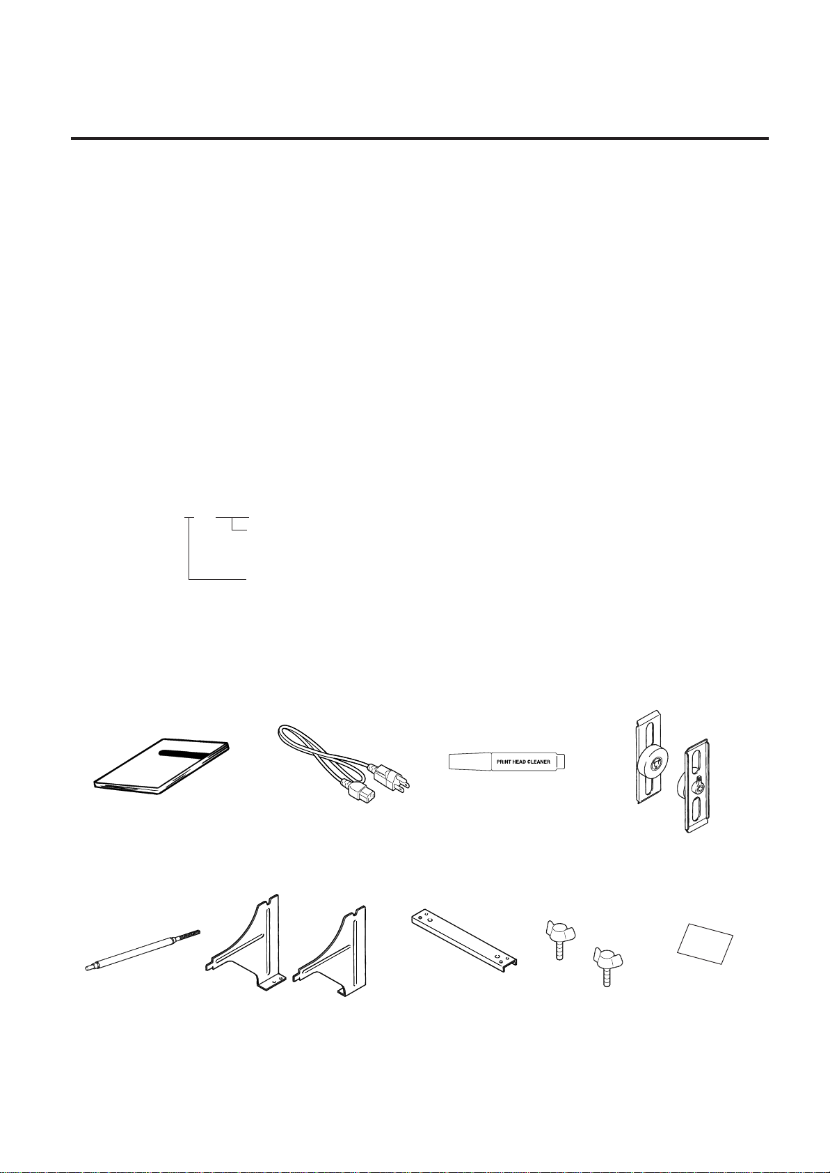
1.2 ACCESSORIES
Quality control
report
Power Cord
Owner's Manual
(EM1-33039)
Print Head Cleaner
(24089500013)
Media Holder
Left/Right Side Holder
Holder Shaft
Holder Base
Thumbscrew
(M-4x6)

2-1
2. SPECIFICATIONS
EM1-33039E
2. SPECIFICATIONS
2.1 PRINTER
2.1 PRINTER
Supply voltage Universal (automatic switching)
85-138 V, 50/60 Hz
187-276 V, 50/60 Hz
Be sure to use a power cord which meets the standard.
Power consumption 3.5 A, 260 W maximum (standby: 360 mA, 20 W maximum)
Operating temperature 5˚C ~ 40˚C
range
Relative humidity 25% ~ 85%RH (no condensation)
Print head Thermal print head 12 dots per mm (305 dots per inch)
Printing methods Thermal direct or Thermal transfer
Print speeds 76.2 mm/sec. (3 inch/sec.), 101.6 mm/sec. (4 inch/sec.),
203.2 mm/sec. (8 inch/sec.) When the media width is 160mm or less.
Maximum print width 213.3 mm (8.40 inches)
Dispensing modes Batch (Continuous), Strip (On-demand) and Cut modes
(Both cut and strip modes are available only when their respective modules
are fitted.)
Message display 20 characters x 1 line
Dimensions 437 mm (width) x 282 mm (depth) x 395 mm (height)
Weight 25 kg (without media and ribbon)
Available bar-code types JAN8, JAN13, EAN8, EAN8 + 2 digits, EAN8 + 5 digits
EAN13, EAN13 + 2digits, EAN13 + 5 digits
UPC-E, UPC-E + 2 digits, UPC-E + 5 digits
UPC-A, UPC-A + 2 digits, UPC-A + 5 digits
MSI, ITF, NW-7, CODE39, CODE93, CODE128
EAN128, Industrial 2 to 5
Two-dimensional code Data Matrix, PDF417,
Fonts Times Roman (6 sizes), Helvetica (6 sizes), Presentation (1 size),
Letter Gothic (1 size), Prestige Elite (2 sizes), Courier (2 sizes),
OCR (2 types), Writable characters (40 types), Outline font (1 type)
Rotations 0˚, 90˚, 180˚, 270˚
Standard interfaces Serial interface (RS-232C)
Parallel interface (Centronics)
Expansion I/O interface
Flash memory card interface
Optional interface High speed PC interface
B-872-QQ
Item
Model
∗
Data Matrix
TM
is a trademark of International Data Matrix, Inc.
PDF417 is a trademark of Symbol Technologies, Inc.
2-2
2. SPECIFICATIONS
EM1-33039E
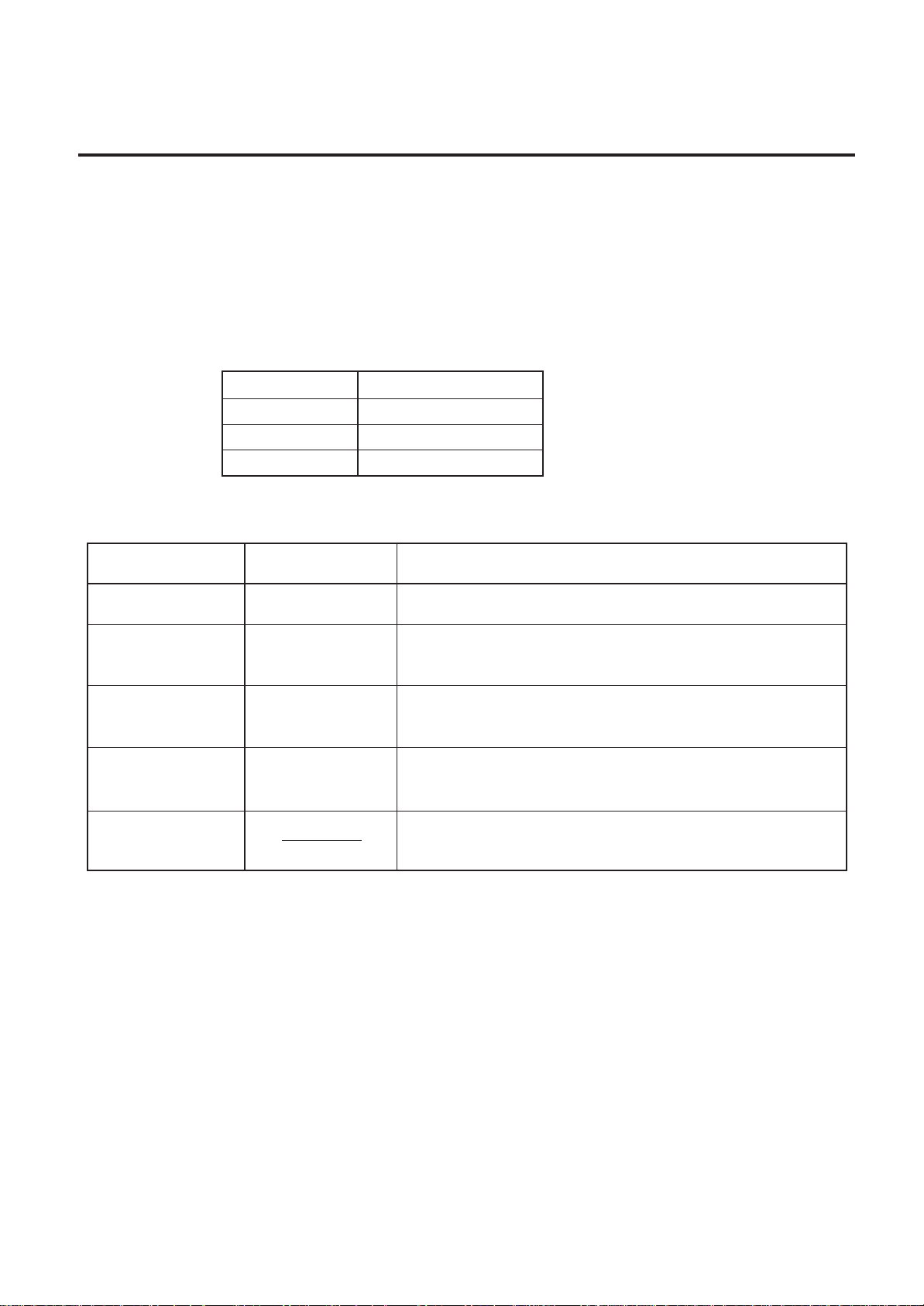
2.2 OPTION
■ Auto Ribbon Saving Mode
Auto ribbon saving function is activated when it is selected by DIP switch (Refer to page 4-1) and
none print area extends for more than 20 mm.
NOTES: 1. To activate ribbon saving function at a speed of 8"/sec., the no print area should extend
more than 25 mm.
2. Depending on the relationship between the outer diameter of rewound ribbon and print
speed, ribbon usage may vary as follows:
Print speed Ribbon loss
3"/sec Approx. 5 mm
4"/sec Approx. 10 mm
8"/sec Approx. 23 mm
2.2 OPTION
Description
A stop and cut swing cutter
This interface kit allows extremely high speed information
transfer between the printer and PC.
This module strips the label from the backing paper with the
take-up block and strip block.
A flash ROM card (1MB and 4MB) for storing logos, writable
characters and formats.
Option Name
Cutter module
High speed PC
interface kit
Strip module
Flash memory
card
Type
B-4208-QM
B-4800-PC-QM
B-4908-H-QM
D-RAM PC Board FMBC0067801
A 2MB RAM upgrade which enhances the image handling
capability of the printer.
2-3
2. SPECIFICATIONS
EM1-33039E
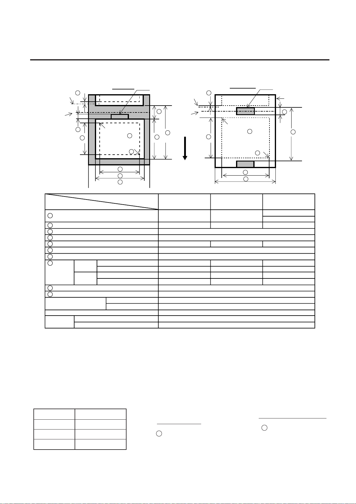
2.3 MEDIA
2.3 MEDIA
Fig. 2-1
NOTES: 1. The media specification other than above are unchanged.
2. When marking black marks on label rolls, the following requirements must be satisfied.
When the gap length is less than 4 mm:
The black mark length should be longer than the gap length.
When the gap length is 4 mm or more:
The black mark should not overlap the gap for more than 4 mm and the following label.
3. When issuing thermal labels at 8"/sec., the print stop position should be set to a minimum of 1 mm inside
the label.
2.4 RIBBON
I I
J
H
H
G
G
D
C
C
1
1
2
2
A
A
F
B
E
Stop
position
Cut
position
Label
Reference
coordinate
Reference
coordinate
Refer to the following
NOTE 2.
Black Mark
(on reverse side)
Stop
position
Cut
position
Feed direction
Tag paper
Black Mark
(on reverse side)
Tag paper
Reference
coordinate
Reference
coordinate
Item
Label dispensing mode
Batch mode Strip mode
10.00 ~ 999.0 25.4 ~ 999.0
7.5 ~ 996.5 22.9 ~ 996.5
101.6 ~ 225.0
98.6 ~ 222.0
2.5 ~ 10.0
1.0
Refer to the following NOTE 2.
160.0
330.6
Ø200 Max.
0.13 ~ 0.17
0.10 ~ 0.17
10.0 ~ 213.3
25.0 ~ 993.0
5.5 ~ 320.0 20.9 ~ 320.0 23.0 ~ 320.0
5.5 ~ 661.3 20.9 ~ 661.3 23.0 ~ 661.3
8.0 ~ 320.0 23.4 ~ 320.0 23.4 ~ 320.0
8.0 ~ 661.3 23.4 ~ 661.3 23.4 ~ 661.3
2.5 ~ 20.0 2.5 ~ 20.0 6.0 ~ 20.0
Label: 38 ~ 999.0
Tag: 25.4 ~ 999.0
Cut mode
A:
Span of one label/tag
B
: Label length
C
: Width including backing paper
D
: Label width
E
: Gap length
F
: Black mark length (Tag paper)
G
: Effective print width
:
Effective
print length
Label
Standard
Max. memory
Standard
Max. memory
Standard
Outer roll diameter
Max. memory
Label
Thickness
Tag
Tag
I
: Print speed up/slow down area
J
: Black mark length (Label)
Maximum effective
length for on the fly issue
H
[Unit: mm]
NOTES: 1. “On the fly issue” means that the printer can draw and print without stopping
between labels.
2. To ensure print quality and print head life use only TOSHIBA TEC specified
media and ribbons.
3. When using the cutter ensure that label length
B
plus inter label gap length
E
exceeds 35 mm. (i.e. label pitch should be greater than 35 mm.)
4. Use of rough media for the ribbon saving issue may cause ribbon smudges.
5. To avoid ribbon wrinkles use the ribbon which is wider than media by 5mm
or more. However, too much difference in width between the two may
cause wrinkles.
Type Spool type
Width 115 mm ~ 224 mm
Length 300 m
Outer diameter Ø72 mm (max.)
3-1
3. OVERVIEW
EM1-33039E
3. OVERVIEW
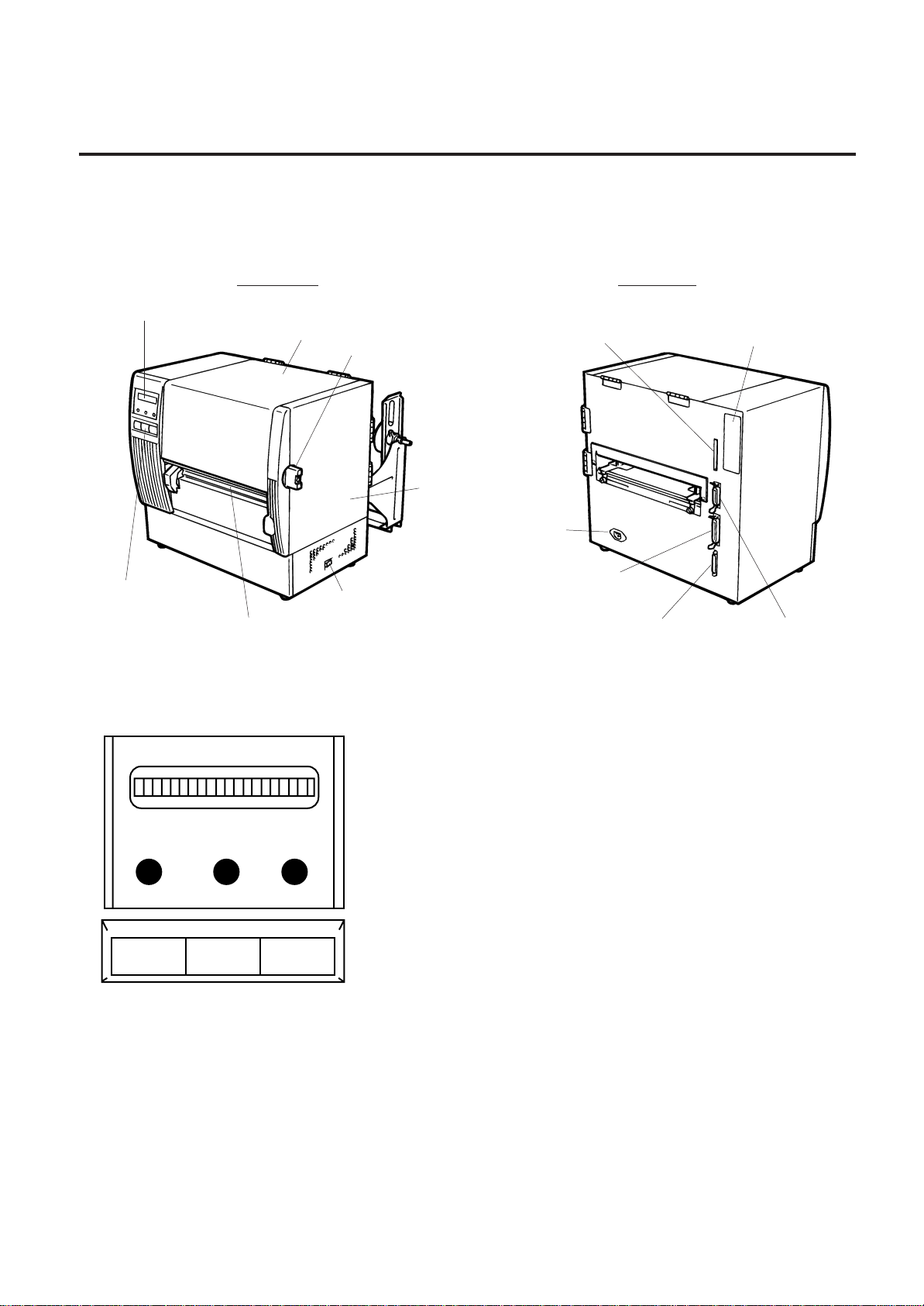
3.1 FRONT/REAR VIEW
3.1 FRONT/REAR VIEW
Front View Rear View
3.2 OPERATION PANEL
POWER ON LINE ERROR
FEED RESTART PAUSE
MESSAGE DISPLAY (LCD)
Displays messages in the language selected by DIP switch.
When power is turned on and it is ready to print, “ON LINE” is
displayed.
POWER LED (Green)
Lights when the power is turned on.
ON-LINE LED (Green)
1) Flashes when communicating with a host computer.
2) On while printing.
ERROR LED (Red)
Lights when a communication error occurs, when the media/ribbon
ends or the printer does not operate correctly.
FEED Key
Feeds paper.
RESTART Key
Resets the printer when paused or when an error occurs.
Used to set the threshold. (Refer to page 11-6)
PAUSE Key
Pauses printing.
Message display shows “PAUSE” and an unprinted count.
Used to set the threshold. (Refer to page 11-6)
Fig. 3-2
Message Display (LCD)
Top Cover
Head Lever
Right Side Cover
Power Switch
0: OFF
1: ONMedia Outlet
Operation Panel
Fig. 3-1
Outlet for the high speed PC
interface cable (Option)
Memory Card Slot
AC Power Inlet
Parallel I/F Connector
(Centronics)
Serial Interface
Connector
(RS-232C)
Expansion I/O
Interface Connector
4-1
4. DIP SWITCH FUNCTIONS
EM1-33039E
4. DIP SWITCH FUNCTIONS
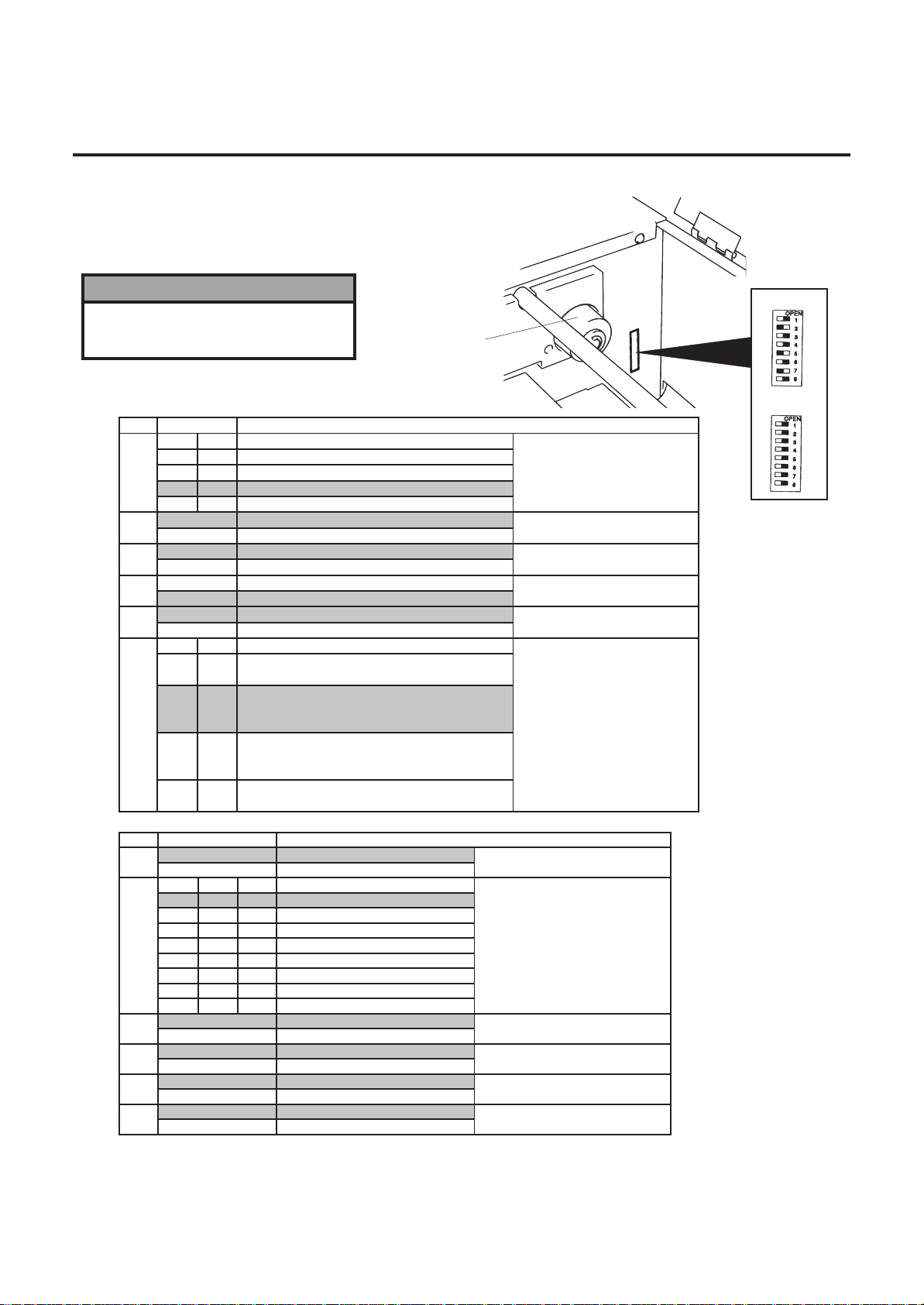
The DIP switches are located to the right of the Guide Wheel.
4. DIP SWITCH FUNCTIONS
NOTES: 1. The shaded settings are the factory default settings. “OFF” means “OPEN”.
2.The Dip switch #1-6 functions in accordance with equipment to be used.
(2) DIP SW 1
(1) DIP SW 2
No. ON/OFF
FUNCTION
1
2
1
Transmission speed
OFF
OFF
2400 BPS
ON
OFF
4800 BPS
OFF ON 9600 BPS
ON 19200 BPS
3
OFF 1 bit
Stop bit length
ON 2 bit
4
OFF 7 bit
Data length
ON
8 bit
5
OFF
Without
Parity chec k
ON Without
6
OFF EVEN
Parity check (effective when DIP
SW #5 is set to O N .)
ON
ODD
7
8
7
Data protocol
OFF OFF
XON/XOFF (No XON is output at the power on time.)
(No XOFF is output at the power off time.)
ON OFF
READY/BUSY (DTR)
(No XON is output at the power on time.)
(No XOFF is output at the power off time.)
OFF
ON
XON/XOFF+READY/BUSY
(XON is output at the power on time.)
(XOFF is output at the power off time.)
ON
ON
XON/XOFF (XON is output at the power on time.)
(XOFF is output at the power off time.)
Guide Wheel
Fig. 4-1
No.
ON/OFF FUNCTION
1
OFF Without
Auto ribbon save function
ON
With
2
3
4
24
Language to display LCD error
message
OFF OFF
OFF
English
ON
OFF
OFF German
OFF
OFF
French
ON
Dutch
OFF
Spanish
Japanese
Italian
Not used
5
OFF Without
Auto media feed after a cut issue
(See page 8-4)
ON
With
6
OFF Without
Head up function in cut mode Refer to
Note 2.
ON With
7
OFF Fixed type
Media sensor selection
ON
Movable type
8
OFF Must be set to OFF
ON
W ARNING!
Turn the POW E R O FF before
switching the functions
DIPSW 2
DIPSW 1
2
ON
8
3
ON
ON OFF
OFF
ON
ON
OFF
OFF
ON
ON
ON
ON
ON
ON
 Loading...