


FILE NO. SVM-03021
SERVICE MANUAL
AIR-CONDITIONER
UNDER CEILING / CONSOLE TYPE
RAV-SM560XT-E / RAV-SM560AT-E RAV-SM800XT-E / RAV-SM800AT-E
R410A
Sep., 2003
|
CONTENTS |
|
1. |
SPECIFICATIONS............................................................................................................. |
1 |
2. |
CONSTRUCTION VIEWS ................................................................................................. |
4 |
3. |
SYSTEMATIC REFRIGERATING CYCLE DIAGRAM ...................................................... |
7 |
4. |
WIRING DIAGRAM ........................................................................................................... |
9 |
5. |
SPECIFICATION OF ELECTRICAL PARTS .................................................................. |
12 |
6. |
REFRIGERANT R410A .................................................................................................. |
13 |
7. |
CONTROL BLOCK DIAGRAM ....................................................................................... |
21 |
8. |
OPERATION DESCRIPTION .......................................................................................... |
22 |
9. |
INSTALLATION PROCEDURE ....................................................................................... |
27 |
10. |
TROUBLESHOOTING CHART ...................................................................................... |
46 |
11. |
DETACHMENTS ............................................................................................................. |
60 |
12. |
EXPLODED VIEWS AND PARTS LIST .......................................................................... |
80 |
1. SPECIFICATIONS
1-1. Indoor Unit
Model name |
|
|
|
|
RAV-SM560XT-E |
|
|
RAV-SM800XT-E |
|
|||||
|
|
|
|
|
|
|
|
|
|
|
|
|
|
|
|
|
|
|
|
Cooling |
|
Heating |
|
Average |
|
Cooling |
Heating |
|
Average |
|
|
|
|
|
|
|
|
|
|
|
|
|
|
|
Standard capacity (Note 1) |
|
kW |
5.0 |
|
5.6 |
|
|
|
6.7 |
8.0 |
|
|
||
|
|
|
|
|
(1.5 Ð 5.6) |
|
(1.5 Ð 6.3) |
|
|
|
(2.2 Ð 8.0) |
(2.2 Ð 9.0) |
|
|
|
|
|
|
|
|
|
|
|
|
|
|
|
|
|
Heating low temp. capacity (Note 1) (kW) |
|
|
|
4.9 |
|
|
|
|
5.8 |
|
|
|||
|
|
|
|
|
|
|
|
|
|
|
|
|
|
|
Energy consumption effect ratio (Cooling) |
|
|
2.67 [D] |
|
3.29 [C] |
|
2.98 |
|
2.46 [E] |
3.00 [D] |
|
2.73 |
||
|
|
|
|
|
|
|
|
|
|
|
|
|
||
|
Power supply |
|
|
|
|
1 phase 220 Ð 240V 50Hz |
|
|
|
|||||
|
|
|
|
|
|
|
|
|
|
|
|
|
|
|
Electrical |
Running current |
|
(A) |
8.95 Ð 8.20 |
|
8.13 Ð 7.46 |
|
|
13.15 Ð 12.06 |
12.91 Ð 11.84 |
|
|
||
|
|
|
|
|
|
|
|
|
|
|
|
|
|
|
Power consumption |
|
(kW) |
1.87 |
|
1.7 |
|
|
|
2.72 |
2.67 |
|
|
||
characteristics |
|
|
|
|
|
|
|
|||||||
|
|
|
|
|
|
|
|
|
|
|
|
|
|
|
|
(Low temp.) |
|
(kW) |
2.18 |
|
|
|
2.29 |
|
|
||||
|
|
|
|
|
|
|
|
|
|
|
|
|
|
|
|
Power factor |
|
(%) |
95 |
|
95 |
|
|
|
94 |
94 |
|
|
|
|
|
|
|
|
|
|
|
|
|
|
|
|
|
|
|
Main unit |
|
|
|
|
|
|
Pure white |
|
|
|
|||
|
|
|
|
|
|
|
|
|
|
|
|
|
|
|
Appearance |
Ceiling panel |
|
Model |
|
|
|
|
|
ÐÐÐ |
|
|
|
|
|
|
(Sold separately) |
|
|
|
|
|
|
|
|
|
|
|
|
|
|
|
Panel color |
|
|
|
|
|
ÐÐÐ |
|
|
|
|
||
|
|
|
|
|
|
|
|
|
|
|
|
|
|
|
|
|
|
Height |
(mm) |
|
|
|
|
633 |
|
|
|
|
|
|
|
|
|
|
|
|
|
|
|
|
|
|
|
|
|
Main unit |
|
Width |
(mm) |
|
|
|
|
1093 |
|
|
|
|
|
|
|
|
|
|
|
|
|
|
|
|
|
|
|
|
Outer |
|
|
Depth |
(mm) |
|
|
|
|
208 |
|
|
|
|
|
dimension |
|
|
|
|
|
|
|
|
|
|
|
|
|
|
Ceiling panel |
|
Height |
(mm) |
|
|
|
|
ÐÐÐ |
|
|
|
|
||
|
|
|
|
|
|
|
|
|
|
|
|
|
|
|
|
|
Width |
(mm) |
|
|
|
|
ÐÐÐ |
|
|
|
|
||
|
(Sold separately) |
|
|
|
|
|
|
|
|
|
||||
|
|
|
|
|
|
|
|
|
|
|
|
|
|
|
|
|
|
Depth |
(mm) |
|
|
|
|
ÐÐÐ |
|
|
|
|
|
|
|
|
|
|
|
|
|
|
|
|
|
|
|
|
Total weight |
Main unit |
|
(kg) |
|
|
|
|
23 |
|
|
|
|
||
|
|
|
|
|
|
|
|
|
|
|
|
|
|
|
Ceiling panel |
|
|
|
|
|
|
ÐÐÐ |
|
|
|
|
|||
|
|
|
|
|
|
|
|
|
|
|
||||
|
|
|
|
|
|
|
|
|
|
|
|
|
|
|
Heat exchanger |
|
|
|
|
|
|
|
|
Finned tube |
|
|
|
||
|
|
|
|
|
|
|
|
|
|
|
|
|
|
|
|
Fan |
|
|
|
|
|
|
Multi blade fan |
|
|
|
|||
|
|
|
|
|
|
|
|
|
|
|
|
|
|
|
Fan unit |
Standard air flow High (Mid./Low) |
(m3/h) |
|
800 (680/580) |
|
|
|
900(750/550) |
|
|
||||
|
|
|
|
|
|
|
|
|
|
|
|
|
|
|
|
Motor |
|
(W) |
|
|
|
|
50 |
|
|
|
|
||
|
|
|
|
|
|
|
|
|
|
|
|
|
|
|
Air filter |
|
|
|
|
|
|
|
|
Washable filter |
|
|
|
||
|
|
|
|
|
|
|
|
|
|
|
|
|
||
Controller (Sold separately) |
|
|
|
|
|
Wireless remote control |
|
|
|
|||||
|
|
|
|
|
|
|
|
|
|
|
|
|
|
|
|
Gas side |
|
(mm) |
|
|
12.7 (1/2Ó) |
|
|
|
15.9 (5/8Ó) |
|
|||
|
|
|
|
|
|
|
|
|
|
|
|
|
|
|
Dimensions pipe |
Liquid side |
|
(mm) |
|
|
6.4 (1/4Ó) |
|
|
|
9.5 (3/8Ó) |
|
|||
|
|
|
|
|
|
|
|
|
|
|
|
|||
|
Drain port |
(Nominal dia.) |
|
|
25 (Polyvinyl chloride tube) |
|
|
|
||||||
|
|
|
|
|
|
|
|
|
|
|
|
|
|
|
Sound level |
High (Mid./Low) (Note 2) |
(dB¥A) |
43 |
|
39 |
|
36 |
|
46 |
42 |
|
37 |
||
|
|
|
|
|
|
|
|
|
|
|
|
|
|
|
Note 1 |
: The cooling capacities and electrical characteristics are measured under the conditions specified by JIS B 8616 |
||
|
based on the reference piping length 7.5 m with 0 meter height. |
||
Note 2 |
: The sound level is measured in an anechoic chamber in accordance with JIS B8616. Normally, the values |
||
|
measured in the actual operating environment become larger than the indicated values due to the effects of |
||
|
external sound. |
|
|
Note |
: Rated conditions |
Cooling |
: Indoor air temperature 27°C DB/19°C WB, Outdoor air temperature 35°C DB |
|
|
Heating |
: Indoor air temperature 20°C DB, Outdoor air temperature 7°C DB/6°C WB |
Ð 1 Ð

• Operation characteristic curve
<Cooling> |
|
|
|
|
|
|
<Heating> |
|
|
|
|
|
|
||
|
14 |
|
|
|
|
|
|
|
|
|
|
|
|
|
|
|
12 |
|
|
|
|
|
|
|
14 |
|
|
|
|
|
|
|
RAV-SM800XT-E |
|
|
|
|
|
|
RAV-SM800XT-E |
|
|
|
||||
|
|
|
|
|
|
|
|
|
|
|
|||||
|
10 |
|
|
|
|
|
|
|
12 |
|
|
|
|
|
|
|
|
|
|
|
|
|
|
|
|
|
|
|
|
|
|
(A) |
|
|
|
|
|
|
|
(A) |
10 |
|
|
|
|
|
|
8 |
|
|
|
|
|
|
|
|
|
|
|
|
|
||
|
|
|
|
|
|
|
|
|
|
|
|
|
|
||
Current |
|
|
|
|
|
|
|
Current |
8 |
|
|
|
|
|
|
6 |
|
|
|
|
|
|
|
|
|
|
|
|
|
||
|
|
|
|
|
|
|
6 |
|
|
|
|
|
|
||
|
|
|
|
|
|
|
|
|
|
|
|
|
|
|
|
|
4 |
|
|
RAV-SM560XT-E |
|
|
|
|
|
RAV-SM560XT-E |
|
||||
|
|
|
|
|
|
|
|
4 |
|
|
|
||||
|
|
|
|
|
|
|
|
|
|
|
|
||||
|
|
|
|
¥ Conditions |
|
|
|
|
|
¥ Conditions |
|
|
|
||
|
|
|
|
|
|
|
|
|
|
|
|
|
|||
|
2 |
|
|
Indoor : DB27ûC/WB19ûC |
|
|
|
|
|
Indoor : DB20ûC |
|
|
|||
|
|
|
Outdoor : DB35ûC |
|
|
2 |
|
|
Outdoor : DB7ûC/WB6ûC |
|
|||||
|
|
|
|
|
|
|
|
|
|||||||
|
|
|
|
Air flow : High |
|
|
|
|
|
|
Air flow : High |
|
|
|
|
|
|
|
|
Pipe length : 7.5m |
|
|
|
|
|
Pipe length : 7.5m |
|
|
|||
|
0 |
|
|
230V |
|
|
|
|
0 |
|
|
230V |
|
|
|
|
15 20 |
40 |
60 |
70 |
80 |
100 |
|
1520 |
40 |
60 |
80 |
90 |
100 |
||
|
0 |
|
0 |
||||||||||||
Compressor speed (rps) |
Compressor speed (rps) |
• Capacity variation ratio according to temperature |
|
|
|
|
|
|
|
|
|
|
|
|
|
|
||||||
<Cooling> |
|
|
|
|
<Heating> |
|
|
|
|
|
|
|
|
|
|
|
||||
|
105 |
|
|
|
|
|
|
120 |
|
|
|
|
|
|
|
|
|
|
|
|
|
100 |
|
|
|
|
|
|
110 |
|
|
|
|
|
|
|
|
|
|
|
|
|
95 |
|
|
|
|
|
|
100 |
|
|
|
|
|
|
|
|
|
|
|
|
|
|
|
|
|
|
|
|
|
|
|
|
|
|
|
|
|
|
|
|
|
|
90 |
|
|
|
|
|
|
90 |
|
|
|
|
|
|
|
|
|
|
|
|
|
|
|
|
|
|
|
|
|
|
|
|
|
|
|
|
|
|
|
|
|
(%) |
85 |
|
|
|
|
|
(%) |
80 |
|
|
|
|
|
|
|
|
|
|
|
|
|
|
|
|
|
|
|
|
|
|
|
|
|
|
|
|
|
|
|||
|
|
|
|
|
|
|
|
|
|
|
|
|
|
|
|
|
|
|
|
|
ratio |
|
|
|
|
|
|
ratio |
70 |
|
|
|
|
|
|
|
|
|
|
|
|
80 |
|
|
|
|
|
60 |
|
|
|
|
|
|
|
|
|
|
|
|
||
|
|
|
|
|
|
|
|
|
|
|
|
|
|
|
|
|
|
|
||
Capacity |
|
|
|
|
|
|
Capacity |
|
|
|
|
|
|
|
|
|
|
|
|
|
75 |
|
|
|
|
|
40 |
|
|
|
|
|
|
|
|
|
|
|
|
||
|
|
|
|
|
|
|
|
50 |
|
|
|
|
|
|
|
|
|
|
|
|
|
70 |
|
|
|
|
|
|
|
|
|
|
|
|
|
|
|
|
|
|
|
|
65 |
|
|
|
|
|
|
30 |
|
|
|
|
|
|
|
|
|
|
|
|
|
|
|
|
|
|
|
|
|
|
|
|
|
|
|
|
|
|
|
|
|
|
60 |
|
|
¥ Conditions |
|
|
|
20 |
|
|
|
|
|
|
¥ Conditions |
|
|
|
||
|
|
|
|
|
|
|
|
|
|
|
|
|
|
|
|
|
||||
|
55 |
|
|
Indoor : DB27ûC/WB19ûC |
|
|
10 |
|
|
|
|
|
|
Indoor : DB20ûC |
|
|
||||
|
|
|
Indoor air flow : High |
|
|
|
|
|
|
|
|
|
Indoor air flow : High |
|
||||||
|
|
|
|
Pipe length : 7.5m |
|
|
|
|
|
|
|
|
|
|
Pipe length : 7.5m |
|
|
|||
|
50 |
|
|
|
|
|
|
0 |
|
|
|
|
|
|
|
|
|
|
|
|
|
32 |
33 |
34 35 36 |
37 38 39 40 41 |
42 |
43 |
|
-14 |
-12 |
-10 |
-8 |
-6 |
-4 |
-2 |
0 |
2 |
4 |
6 |
8 |
10 |
Outsoor temp. (ûC) |
Outsoor temp. (ûC) |
Ð 2 Ð
1-2. Outdoor Unit
Model name |
|
|
|
RAV-SM560AT-E |
|
RAV-SM800AT-E |
|
|
|
|
|
|
|
|
|
Appearance |
|
|
|
Silky shade (Muncel 1Y8.5/0.5) |
|||
|
|
|
|
|
|
|
|
Power supply |
|
|
|
1 phase 230V (220 Ð 240V) 50Hz |
|||
|
|
|
(Power exclusive to outdoor is required.) |
||||
|
|
|
|
|
|||
|
|
|
|
|
|
|
|
|
|
Type |
|
Hermetic compressor |
|||
|
|
|
|
|
|
|
|
Compressor |
|
Motor |
(kW) |
1.1 |
|
1.6 |
|
|
|
|
|
|
|
|
|
|
|
Pole |
|
|
4 poles |
||
|
|
|
|
|
|
|
|
Refrigerant charged |
(kg) |
R410A 0.9 |
|
R410A 1.5 |
|||
|
|
|
|
|
|
||
Refrigerant control |
|
Pulse motor valve |
|||||
|
|
|
|
|
|
|
|
|
|
Standard length |
|
20 (without additional charge) |
|||
|
|
|
|
|
|
|
|
|
|
Max. total length |
(m) |
30 |
|
50 |
|
|
|
|
|
|
|
|
|
Pipe |
|
Over 20m |
|
Add 20g/m (Max. 200g) |
|
Add 40g/m (Max. 1200g) |
|
|
|
|
|
|
|
|
|
|
|
Height difference |
Outdoor lower |
(m) |
|
15 |
|
|
|
|
|
|
|
|
|
|
|
Outdoor higher |
(m) |
|
30 |
||
|
|
|
|
||||
|
|
|
|
|
|
|
|
|
|
Height |
(mm) |
595 |
|
795 |
|
Outer |
|
|
|
|
|
|
|
|
Width |
(mm) |
780 |
|
780 |
||
dimension |
|
|
|||||
|
|
|
|
|
|
|
|
|
|
Depth |
(mm) |
270 |
|
270 |
|
|
|
|
|
|
|
|
|
Total weight |
|
|
(kg) |
35 |
|
55 |
|
|
|
|
|
|
|
|
|
Heat exchanger |
|
|
|
|
Finned tube |
||
|
|
|
|
|
|
|
|
|
|
Fan |
|
|
Propeller fan |
||
|
|
|
|
|
|
|
|
Fan unit |
|
Standard air flow High |
(m³/h) |
2400 |
|
3400 |
|
|
|
|
|
|
|
|
|
|
|
Motor |
(W) |
43 |
|
63 |
|
|
|
|
|
|
|
|
|
Connecting |
|
Gas side |
(mm) |
¯12.7 (1/2Ó) |
|
¯15.9 (5/8Ó) |
|
|
|
|
|
|
|
|
|
pipe |
|
Liquid side |
(mm) |
¯6.4 (1/4Ó) |
|
¯9.5 (3/8Ó) |
|
|
|
|
|||||
|
|
|
|
|
|
|
|
Protection device |
|
Discharge temp. sensor |
|||||
|
Over-current sensor |
||||||
|
|
|
|
|
Compressor thermo. |
||
|
|
|
|
|
|
|
|
Sound level |
|
High (Mid./Low) |
(dB¥A) |
46/48 |
|
48/50 |
|
(Note 2) |
|
(Cooling/Heating) |
|
||||
|
|
|
|
|
|||
|
|
|
|
|
|
|
|
Note 1 : The sound level is measured in an anechoic chamber in accordance with JIS B8616. Normally, the values measured in the actual operating environment become larger than the indicated values due to the effects of external sound.
Note 2 : Rated conditions Cooling : Indoor air temperature 27¡C DB/19¡C WB, Outdoor air temperature 35¡C DB Heating : Indoor air temperature 20¡C DB, Outdoor air temperature 7¡C DB/6¡C WB
Ð 3 Ð

2. CONSTRUCTION VIEWS
2-1. Indoor Unit
Front panel
1093 |
208 |
|
633
Knock out system
Grille air inlet
Back body
For stud bolt |
200 Min |
(¯8 Ð ¯10)
For stud bolt (¯6)
330
165
|
1093 |
|
|
|
|
1015 |
|
|
|
|
742 |
|
|
|
|
450 |
|
|
|
20 |
20 |
|||
|
|
|
|
|
¯74
UNDER CEILING & CONSOLE INSTALLATION
Installation plate
Mount plate
M10 Suspention bolt
633 |
|
|
460 |
|
|
|
|
160 |
Min |
57 |
18 |
70 |
Wireless remote control |
|
|
||
Knock out system
Ð 4 Ð
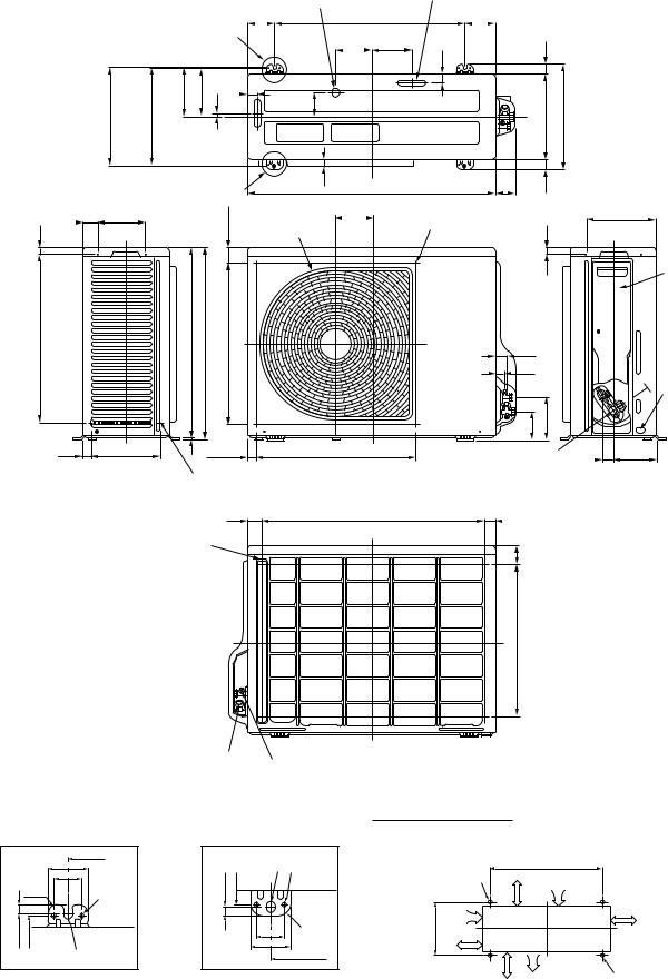
2-2. Outdoor Unit (RAV-SM560AT-E)
Drain hole (¯25) |
Drain hole (2-¯20 x 88 long hole) |
|
|
|
|
83 |
600 |
97 |
A legs |
115.3 125 |
|
|
29 |
|
|
30 |
|
308 |
hole(Longpitch |
anchorFor bolt) |
302 |
hole¯6pitch |
153 |
150 |
11 |
76 |
|
270 |
330 |
|
|
|
|
|
|
|
30 |
|
|
|
|
|
|
|
|
|
|
|
B legs |
21 |
780 |
31 |
|
|
|
|
|
|
|
|
|
|
|
||
|
|
|
|
|
|
|
|
|
|
|
49.5 |
147 |
|
(49.3) |
115.3 |
Discharge guide mounting hole |
216 |
||
21 |
|
|
Discharge guard |
(4-¯4 embossing) |
|
|
|
|
|
|
|
|
|
|
|
||
|
|
|
|
|
|
|
|
|
|
|
|
center dividing) |
|
|
|
21 |
|
521 |
|
593 598 |
|
|
31 |
|
|
|
|
|
|
(Fan500 |
|
|
23 |
|
|
|
|
|
|
|
|
|
|
|
|
|
|
|
|
|
90.6 |
132 |
|
25 |
220 |
|
|
500 (Fan center dividing) |
Charge port 31 |
134 |
||
Protective net mounting hole (2-¯4 embossing)
43 |
707 |
30 |
Protective net mounting hole |
|
|
(4-¯4 embossing) |
|
60 |
|
|
Valve cover
Earth terminal
475
Refrigerant pipe connecting port
(¯12.7 flare at gas side) Refrigerant pipe connecting port (¯6.4 flare at liquid side)
Space required for service
|
|
600 |
|
|
|
52 |
|
|
|
36 |
|
11 |
R15 |
2-¯6 hole |
|
308 |
302 |
Product |
|
external line |
|||
|
|
||
|
¯11 x 14 U-shape hole |
||
Details of A legs
|
¯11 x 14 U- |
|
2-¯11 x 14 U-shape holes |
||
|
shape holes |
2-¯6 hole |
|||
|
(For ¯8Я10 anchor bolt) |
||||
308 |
302 |
external |
|||
|
150 moreor |
||||
|
|
Product |
|
|
|
|
|
line |
|
|
|
11 |
|
R15 |
365 |
150 |
|
36 |
or more |
||||
|
|
||||
|
|
|
|||
|
52 |
|
|
|
|
|
|
600 |
|
|
|
Details of B legs |
|
|
500 |
||
|
|
or more |
|||
600
Suction port
|
300 |
|
or more |
Discharge |
(Minimum |
port |
distance up to wall) |
Discharge |
2-¯11 x 14 long hole |
|
port |
||
(For ¯8Я10 anchor bolt) |
||
|
Ð 5 Ð
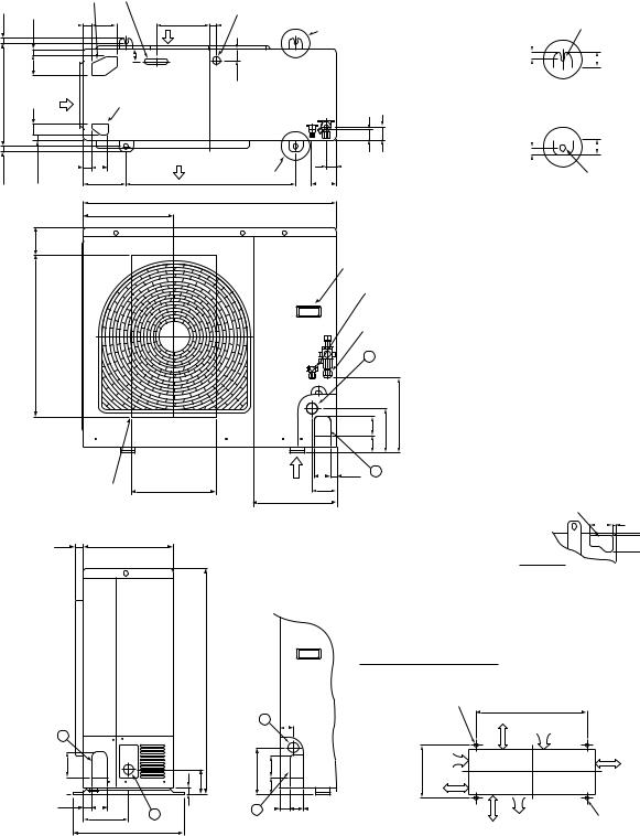
2-3. Outdoor Unit (RAV-SM800AT-E)
Knockout
(For draining) Drain hole (¯20 x 88 burring hole)
17.5 |
|
|
|
29 |
90 |
191 |
Drain hole (¯25 burring hole) |
|||
|
21 |
20 |
Part B |
|
|
|||||
|
|
|
Suction |
|
|
|
||||
|
|
|
|
|
|
port |
|
|
|
|
|
pitch |
bolt) |
70 |
Suction |
43 |
|
40 |
|
|
|
365 |
hole(Long |
anchorfor |
40 |
Knockout |
|
|
|
|
|
|
port |
|
|
|
|
|
|||||
|
|
|
|
(For draining) |
|
|
|
|
||
|
|
|
|
|
|
|
|
|
||
17.5 |
|
|
|
26 |
60 |
Discharge |
|
43 |
39 |
47 |
|
|
21 |
port |
Part A |
|
|
||||
|
|
|
150 |
300 |
95 |
|
|
|||
|
|
|
|
|
|
900 |
|
|
|
|
|
|
|
|
|
314 |
|
|
|
|
|
|
|
Installation bolt hole |
|||||||
17.5 |
|
(¯12 x 17 U-shape holes) |
|||||||
|
|
|
|
|
|
|
|
|
|
|
|
|
40 |
|
|
|
|||
|
Details of B part |
||||||||
|
Details of A part |
||||||||
|
|
|
|
|
|
|
|
|
|
17.5 |
|
|
|
|
40 |
|
|
|
|
|
Installation bolt hole |
||||||||
|
|||||||||
|
|
(¯12 x 17 U-shape holes) |
|||||||
|
|
||||||||
101 |
|
Handles |
|
|
|
|
|
||
|
|
(Both sides) |
||
|
|
Refrigerant pipe connecting port |
||
565 |
|
(¯9.5 flare at liquid side) |
||
|
Refrigerant pipe connecting port |
|||
|
|
(¯15.9 flare at gas side) |
||
|
|
2 |
|
|
|
|
60 67 |
154 |
264 |
Discharge guide |
Z |
60 27 |
1 |
|
300 |
96 |
|
|
|
mounting hole |
|
|
||
(4-¯4 embossing) |
307 |
|
|
Knockout for lower piping |
|
|
|
||
86 7
28 320
Z views
58 7
1
90 60 27
27
|
|
|
|
|
Space required for service |
|
|
|
795 |
|
|
2-¯12 x 17 U-shape holes |
|
|
|
|
|
|
||
|
|
|
|
|
(For ¯8Я10 anchor bolt) |
|
|
|
|
|
2 |
46 |
150 moreor |
|
|
|
|
|
||
|
25 |
85 |
165 |
8060 |
365 |
150 |
|
|
|
|
|
|
or more |
58 |
2 |
|
|
1 30 |
45 |
500 |
161 |
|
|
|
|
||
|
400 |
|
|
|
|
or more |
600
Suction port
|
150 |
|
or more |
Discharge |
(Minimum |
port |
distance up to wall) |
Discharge |
2-¯12 x 17 long hole |
|
port |
||
(For ¯8Я10 anchor bolt) |
||
|
Ð 6 Ð

3. SYSTEMATIC REFRIGERATING CYCLE DIAGRAM
3-1. RAV-SM560XT-E / RAV-SM560AT-E
Indoor unit
TCJ sensor
Air heat exchanger
TC sensor
Outer diameter of refrigerant pipe
Gas side A |
Liquid side B |
|
|
6.4 mm |
12.7 mm |
|
|
TS sensor
TD sensor
4-way valve (VT7101D)
Muffler19 x L160
Rotary compressor (DA130A1F-23F)
Refrigerant pipe |
Refrigerant pipe |
at liquid side |
at gas side |
Outer dia. B |
Outer dia. A |
Max 30m
Packed valve |
|
Packed valve |
Outer dia. B |
Outdoor unit |
Outer dia. A |
|
|
|
|
|
PMV |
|
|
(SKV-18D26) |
TO sensor |
|
|
|
|
Strainer |
|
TE |
|
|
sensor |
|
Heat exchanger8 multiple thread
ripple 1 row 22 stages FP1.3 flat fin
Distributor
R410A 0.9 kg
Cooling
Heating
|
|
Pressure |
Pipe surface temperature (°C) |
Compressor |
|
Indoor/Outdoor |
|||||
|
|
|
|
|
|
|
|
|
|||
|
|
(MPa) |
Discharge |
Suction |
Indoor heat |
Outdoor heat |
revolutions |
Indoor |
temp. conditions |
||
|
|
exchanger |
exchanger |
per second |
fan |
(DB/WB) (°C) |
|||||
|
|
|
|
|
|
||||||
|
|
|
|
|
|
|
|
(rps) |
|
|
|
|
|
Pd |
Ps |
(TD) |
(TS) |
(TC) |
(TE) |
|
Indoor |
Outdoor |
|
|
|
* |
|
||||||||
|
|
|
|
|
|
|
|
|
|
|
|
|
|
|
|
|
|
|
|
|
|
|
|
|
Standard |
3.1 |
0.9 |
85 |
13 |
10 |
47 |
74 |
HIGH |
27/19 |
35/Ð |
|
|
|
|
|
|
|
|
|
|
|
|
Cooling |
Overload |
3.8 |
1.0 |
96 |
13 |
12 |
60 |
71 |
HIGH |
32/24 |
43/Ð |
|
|
|
|
|
|
|
|
|
|
|
|
|
Low load |
0.9 |
0.5 |
25 |
7 |
10 |
5 |
28 |
LOW |
18/15.5 |
Ð5/Ð |
|
|
|
|
|
|
|
|
|
|
|
|
|
Standard |
2.8 |
0.6 |
87 |
3 |
46 |
1 |
87 |
HIGH |
20/Ð |
7/6 |
|
|
|
|
|
|
|
|
|
|
|
|
Heating |
Overload |
3.3 |
1.1 |
78 |
22 |
55 |
16 |
55 |
LOW |
30.Ð |
24/18 |
|
|
|
|
|
|
|
|
|
|
|
|
|
Low load |
1.7 |
0.2 |
110 |
Ð20 |
26 |
Ð22 |
110 |
HIGH |
0 |
Ð20/(70%) |
|
|
|
|
|
|
|
|
|
|
|
|
*4 poles are provided to this compressor.
The compressor frequency (Hz) measured with a clamp meter is 2 times of revolutions (rps) of the compressor.
Ð7 Ð
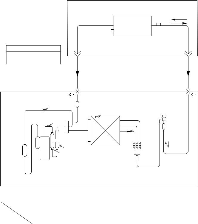
3-2. RAV-SM800XT-E / RAV-SM800AT-E
Indoor unit
Outer diameter of refrigerant pipe
Gas side A |
Liquid side B |
|
|
9.5 mm |
15.9 mm |
|
|
TS sensor
TD sensor
TCJ sensor
Air heat exchanger
TC sensor
|
Refrigerant pipe |
|
Refrigerant pipe |
|
|
at liquid side |
|
at gas side |
|
|
Outer dia. B |
|
Outer dia. A |
|
|
|
|
|
Max |
|
|
|
|
50m |
Pd |
Packed valve |
|
Packed valve |
Ps |
|
Outer dia. B |
Outdoor unit |
Outer dia. A |
|
|
|
|
|
|
|
Strainer |
|
Modulating (PMV) |
|
|
|
(SKV-18D26) |
|
|
|
|
|
|
|
|
TO sensor |
|
|
|
|
|
|
Strainer |
|
4-way valve
Accumulator |
Muffler (STF-0213Z) |
(1500cc) |
25 x L210 |
|
|
|
25 x L160 |
|
Rotary compressor |
|
(DA220A2F-20L) |
TE sensor
Heat exchanger 8 1 row 30 stages FP1.3 flat fin
Capillary3 x 2
x L530
R410A 1.5 kg
 Cooling
 Heating
|
|
Pressure |
Pipe surface temperature (°C) |
Compressor |
|
Indoor/Outdoor |
|||||
|
|
|
|
|
|
|
|
|
|||
|
|
(MPa) |
Discharge |
Suction |
Indoor heat |
Outdoor heat |
revolutions |
Indoor |
temp. conditions |
||
|
|
exchanger |
exchanger |
per second |
fan |
(DB/WB) (°C) |
|||||
|
|
|
|
|
|
||||||
|
|
|
|
|
|
|
|
(rps) |
|
|
|
|
|
Pd |
Ps |
(TD) |
(TS) |
(TC) |
(TE) |
|
Indoor |
Outdoor |
|
|
|
* |
|
||||||||
|
|
|
|
|
|
|
|
|
|
|
|
|
Standard |
3.3 |
0.9 |
89 |
8 |
8 |
40 |
64 |
HIGH |
27/19 |
35/Ð |
|
|
|
|
|
|
|
|
|
|
|
|
Cooling |
Overload |
3.7 |
1.1 |
87 |
17 |
14 |
46 |
45 |
HIGH |
32/24 |
43/Ð |
|
|
|
|
|
|
|
|
|
|
|
|
|
Low load |
1.0 |
0.8 |
22 |
2 |
1 |
1 |
24 |
LOW |
18/15.5 |
Ð5/Ð |
|
|
|
|
|
|
|
|
|
|
|
|
|
Standard |
3.3 |
0.6 |
93 |
0 |
54 |
0 |
70 |
HIGH |
20/Ð |
7/6 |
|
|
|
|
|
|
|
|
|
|
|
|
Heating |
Overload |
3.1 |
1.1 |
75 |
20 |
52 |
15 |
24 |
LOW |
30.Ð |
24/18 |
|
|
|
|
|
|
|
|
|
|
|
|
|
Low load |
2.0 |
0.2 |
90 |
Ð26 |
25 |
Ð25 |
90 |
HIGH |
0 |
Ð20/(70%) |
|
|
|
|
|
|
|
|
|
|
|
|
*4 poles are provided to this compressor.
The compressor frequency (Hz) measured with a clamp meter is 2 times of revolutions (rps) of the compressor.
Ð8 Ð
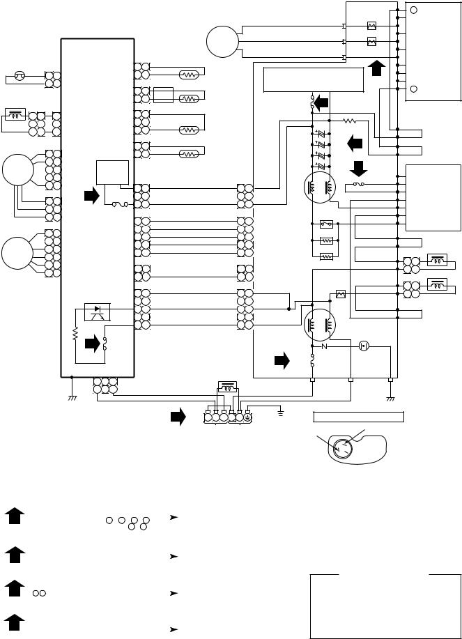
4. WIRING DIAGRAM
4-1. Indoor Unit
SWITCH PCB MCC-1428B
CN101 1 2 3
GRY
GRY
WHI
HEAT
EXCHANGER
SENSOR (TCJ)
FOR FLOAT SWITCH |
1 |
2 |
(OPTION) |
||
When you use float |
1 |
2 |
switch you should cut J401
1 |
RAYSINFRAREDRECEIVE |
INDICATIONAND PARTS |
|
|
|
|
|
|
LOUVER MOTOR
1 |
2 |
3 |
CN402 |
CN100 1 |
2 |
3 |
10 10 |
WHI |
10 10 |
|
|
|||
9 |
9 |
BLU |
9 |
9 |
|
POWER |
|
BLU |
4 |
||||||
SUPPLY |
|||||||
8 |
8 |
BLU |
8 |
8 |
CIRCUIT |
||
7 |
7 |
7 |
7 |
|
|||
6 |
6 |
BLUBLU |
6 |
6 |
|
C02 |
|
5 |
5 |
BLU |
5 |
5 |
|
|
|
4 |
4 |
4 |
4 |
|
DB01 |
||
3 |
3 |
BLU |
3 |
3 |
|
||
|
|
||||||
2 |
2 |
BLU |
2 |
2 |
|
|
|
1 |
1 |
BLU |
1 |
1 |
|
R01 |
|
CN25 |
|
CN13 |
|
C01 |
|||
BRW |
1 |
1 |
5 |
|
|
RED |
2 |
2 |
|
|
|
ORN |
3 |
3 |
|
|
|
YEL |
4 |
4 |
|
|
|
PNK |
5 |
5 |
|
|
|
BLU |
6 |
6 |
IC04 |
C15 |
|
|
CN07 |
||||
|
|
|
|
||
|
|
|
R507 |
|
|
|
|
|
R09 |
|
R21 |
|
|
|
|
|
|
|
|
|
R22 |
FUSE |
|
|
|
|
250VAC |
|
|
|
|
|
|
|
|
|
|
|
SG01 |
F01 |
3 |
|
|
|
|
|
|
|
|
|
|
T6.3A |
|
|
|
|
BLK |
P04 |
CN30 |
|
|
|
|
|
|
|
|
|
|
|
BLK |
2 1
1 2 |
CN05 |
1 2 |
CN03 |
BLK |
|
|
THERMO |
|
J401 |
|
|
2 |
2 |
|
|
SENSOR |
|
DC12V |
|
|
1 |
1 |
BLK |
|
|
(TA) |
IC03 |
|
2 |
2 |
BLK |
|
|
HEAT |
|
DC5V |
|
|
|
|||||
|
BLK |
|
|
|||||
|
|
|
|
|||||
|
|
|
1 |
1 |
|
|
EXCHANGER |
|
|
|
|
CN01 |
|
|
|
SENSOR |
|
|
|
R506 |
|
|
|
(TC) |
||
|
|
|
|
|
|
|
||
|
|
|
|
|
|
|
|
|
CR502 |
CR501 |
|
1 |
1 |
|
|
|
|
|
|
WHI 1 |
1 |
WHI |
||||
|
|
|
2 |
2 |
||||
|
|
|
3 |
3 |
|
2 |
2 |
|
RY501 |
|
|
4 |
4 |
RED |
3 |
3 |
RED |
|
|
|
5 |
5 |
|
4 |
4 |
|
|
C501 |
CN10 |
BLK |
5 |
5 |
BLK |
||
MCC-1428A |
|
|
|
|
|
6 |
6 |
|
|
|
|
|
|
|
|
|
|
R405 |
CR401 |
RY401 |
|
3 |
3 |
BRW |
3 |
3 |
BLU |
2 |
2 |
2 |
2 |
||
1 |
1 |
GRY |
1 |
1 |
PUR |
CN11 |
YEL |
|
|
GRY |
|
|
|
|
FAN-MOTOR |
||
|
|
|
|
|
100ÓC |
32 FOR DRAIN PUMP
(OPTION)
1
CN401
|
CN31 |
CN23 |
|
WHI |
RED |
INDOOR |
GRN&YEL |
|
|
INDOOR |
|
2 3 |
TERMINAL |
||
BLOCK |
UNIT |
||
OUTDOOR
UNIT
SIMPLE CHECK POINTS FOR DIAGNOSING FAULTS
Check items |
Diagnosis result |
|||
|
|
|
||
1 |
OPERATION |
Check to see if OPERATION indicator goes on and off when the main switch |
||
indicator |
or breaker is turned on. |
|
|
|
|
|
|
|
|
2 |
Terminal |
Check the power supply voltage between |
1 |
- 2 (Refer to the name plate.) |
block |
Chack the fluctuate voltage between 2 - |
3 |
(DC15 to 60V) |
|
|
|
|
||
3 |
Fuse |
Check to see if the fuse blows out. (Check the varistor. : R22, R21) |
||
6.3A |
|
|
|
|
|
|
|
||
4 |
DC 5V |
Check the voltage at the No.8 pin on CN13 connector of the infrared receiver. |
||
(Check the transformer and the power supply circuit of the rated voltage.) |
||||
|
|
|
||
5 |
DC 12V |
Check the voltage at the brown lead of the louver motor. |
||
(Check the transformer and the power supply circuit of the rated voltage.) |
||||
|
|
|
|
|
Color
Identification
BRW : BROWN RED : RED WHI : WHITE YEL : YELLOW BLU : BLUE BLK : BLACK GRY : GRAY PNK : PINK ORN : ORANGE
GRN&YEL : GREEN& YELLOW
GRN : GREEN
PUR : PURPLE
Ð 9 Ð
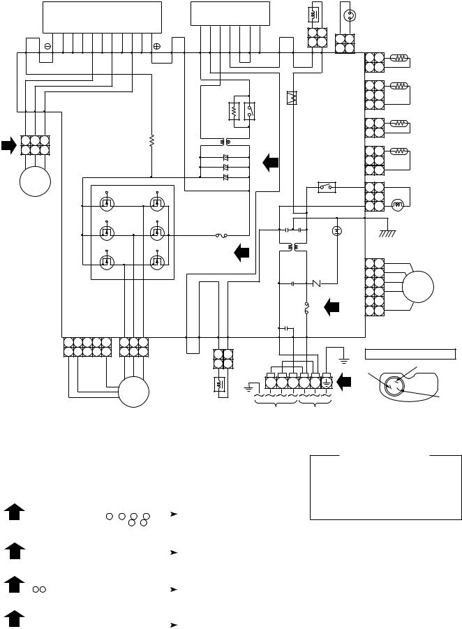
4-2. Outdoor Unit (RAV-SM560AT-E) |
|
|
|
|
|
|
|
|
|
|
|
|
|
|
|||||||||||||
|
|
|
Q200 |
|
|
|
|
|
|
|
|
|
DB01 |
|
|
|
REACTOR |
|
|
THERMOSTAT |
|
||||||
|
|
|
|
|
|
|
|
|
|
|
|
CONVERTER |
|
|
|
|
|
|
|
||||||||
|
|
|
|
|
|
|
|
|
|
|
|
|
|
|
|
|
|
|
|
|
|||||||
|
|
|
|
|
IGBT MODULE |
|
|
|
|
|
|
|
|
|
|
FOR |
|
|
|
||||||||
|
|
|
|
|
|
|
|
|
MODULE |
|
|
|
|
|
|
|
|
|
|||||||||
|
|
|
|
|
|
|
|
|
|
|
|
|
|
|
COMPRESSOR |
|
|||||||||||
|
|
|
|
|
|
|
|
|
|
|
|
|
|
|
|
|
|
|
|
|
|
|
|
||||
|
BLU |
|
|
|
EW |
BW |
|
|
|
BRW |
|
|
|
|
ORN |
|
2 |
1 |
2 |
1 CN500 |
|
|
|||||
|
|
|
BZ |
BY |
BX |
EV BV |
EU |
BU |
|
+ ~ |
|
|
|
|
|
|
2 |
1 |
|
|
|||||||
|
|
|
|
Ð |
~ A E G |
P10 |
|
P09 |
2 |
1 |
|
|
TE |
||||||||||||||
|
|
|
|
|
|
|
|
|
|||||||||||||||||||
|
|
|
|
|
|
|
|
|
|
|
|
|
|
|
|
|
|
||||||||||
|
P17 P18 |
|
|
|
|
|
|
|
|
P20 |
P19 |
|
|
|
|
|
P08 |
P07 |
CN600 |
1 |
1 |
|
|
||||
|
|
|
|
|
|
|
|
|
|
|
|
|
|
|
|
|
|
|
|
|
|
||||||
|
|
|
|
|
|
|
|
|
|
|
|
|
|
|
|
|
|
|
|
|
|
|
|
2 |
2 |
|
|
|
|
|
|
|
|
|
|
|
|
|
|
|
|
|
|
|
|
|
|
|
|
|
|
1 |
1 |
TD |
|
|
|
|
|
|
|
|
|
|
|
|
|
|
ELECTRONIC |
|
|
|
|
|
|
|
|
|
|||||
|
|
|
|
|
|
|
|
|
|
|
|
|
|
|
CT |
|
|
|
CN601 2 |
2 |
|
|
|||||
P23 |
P22 |
P21 |
|
|
|
|
|
|
|
|
|
STARTER |
|
|
|
|
|
|
|
|
|||||||
|
|
|
|
|
|
|
|
|
|
|
|
POWER |
|
|
|
|
|
|
3 |
3 |
|
|
|||||
|
|
|
|
|
|
|
|
|
|
|
|
|
|
|
|
|
|
|
|
|
|
|
|
|
|
||
BLK |
WHI |
RED |
|
|
|
|
|
|
|
|
|
|
|
|
RELAY |
|
|
|
|
|
|
1 |
1 |
TO |
|||
|
|
P.C. BOARD |
|
|
|
|
|
|
|
|
|
|
|
|
CN602 |
|
|
||||||||||
|
|
|
|
|
|
|
|
|
|
|
|
|
|
2 |
2 |
|
|
||||||||||
4 |
3 |
2 |
1 |
|
|
(MCC-813) |
|
|
|
|
|
|
|
|
|
|
|
|
|
|
|
|
TS |
||||
3 |
2 |
1 |
|
|
|
|
|
|
|
|
|
|
Ð |
+ |
C12 |
|
|
|
|
|
|
|
1 |
1 |
|||
|
|
|
|
|
|
|
|
|
|
|
|
|
|
|
|
|
|
|
|
||||||||
|
|
|
|
|
|
|
|
|
|
|
|
|
|
|
3 |
|
|
|
|
|
CN603 2 |
2 |
|
|
|||
|
|
|
|
|
|
|
|
|
|
|
|
|
|
Ð |
+ |
C13 |
|
|
|
|
|
|
|
||||
|
|
|
|
|
|
|
|
|
|
|
|
|
|
|
|
|
|
|
|
3 |
3 |
|
|
||||
|
CM |
|
|
|
|
|
|
|
|
|
|
Ð |
+ |
C14 |
|
|
|
|
RELAY |
|
|
|
|||||
|
|
|
|
|
|
|
|
|
Q300 |
|
|
|
|
|
|
|
|
|
|
||||||||
|
|
|
|
|
|
|
|
|
|
|
|
|
|
|
|
|
1 |
1 |
|
|
|||||||
|
|
|
|
|
|
|
|
|
|
|
|
|
|
|
|
|
|
|
|
|
|
|
|||||
COMPRESSOR |
|
|
|
|
|
|
|
|
|
|
|
|
|
|
|
|
|
|
CN701 2 |
2 |
|
|
|||||
|
|
|
|
|
|
|
|
|
|
|
|
|
|
|
|
|
|
|
|
3 |
3 |
|
|
||||
|
|
|
|
|
|
|
|
|
|
|
|
|
|
|
|
|
|
|
|
|
|
|
|
|
COIL FOR |
||
|
|
|
|
|
|
|
|
|
|
|
|
|
|
|
|
|
|
|
|
|
|
|
|
|
|
|
|
|
|
|
|
|
|
|
|
|
|
|
|
|
|
|
|
|
|
|
|
|
|
|
P06 |
|
BLK |
4-WAY VALVE |
|
|
|
|
|
|
|
|
|
|
|
|
|
|
F04 |
|
|
|
|
|
|
|
SURGE |
|
|
|
|
||
|
|
|
|
|
|
|
|
|
|
|
|
|
FUSE |
2 |
|
|
|
|
|
ABSORBER |
|
|
|
|
|||
|
|
|
|
|
|
|
|
|
|
|
|
|
T3. 15A |
|
|
|
|
|
|
|
1 |
1 |
BLK |
|
|||
|
|
|
|
|
|
|
|
|
|
|
|
|
250V~ |
|
|
|
|
|
|
|
|
|
|||||
|
|
|
|
|
|
|
|
|
|
|
|
|
|
|
|
|
|
|
|
VARISTOR |
|
2 |
2 |
YEL |
|
||
|
|
|
|
|
|
|
|
|
|
|
|
|
|
|
|
|
|
|
|
|
|
|
|
3 |
3 |
RED |
|
|
|
|
|
|
|
|
|
|
|
|
|
|
|
|
|
|
|
|
|
|
|
|
|
4 |
4 |
ORN PMV |
|
|
|
|
|
|
|
|
|
|
|
|
|
|
|
|
|
|
|
FUSE |
|
|
2 |
|
5 |
5 |
RED |
|
|
|
|
|
|
|
|
|
|
|
|
|
|
|
|
|
|
|
|
T25A |
F01 |
|
6 |
6 |
GRY |
PULSE |
|||
|
|
|
|
|
|
|
|
|
|
|
|
|
|
|
|
|
|
250V~ |
|
|
|
|
CN703 |
MODULATING |
|||
|
|
|
|
|
|
|
|
|
|
|
|
|
|
|
|
|
|
|
|
|
|
|
|
VALVE |
|||
|
|
|
|
|
|
|
|
|
|
|
|
|
|
|
|
|
|
|
|
|
|
|
|
|
|
|
|
|
|
|
|
|
|
|
|
|
|
|
|
P14 |
P13 |
|
|
P02 |
|
P03 P01 |
|
|
|
|
|
|
|||
|
|
|
CN301 5 |
|
4 |
3 |
2 |
1 |
3 |
2 |
1 |
CN300 |
P12 |
P11 |
WHI |
ORN |
BLK |
|
|
|
|
|
|
|
|
||
|
|
|
5 |
|
4 |
3 |
2 |
1 |
3 |
2 |
1 |
|
PUR |
2 |
1 |
|
|
|
|
|
TERMINAL OF COMPRESSOR |
||||||
|
|
|
|
|
|
|
|
|
|
|
|
|
|||||||||||||||
|
|
|
GRY |
PNK |
|
YEL |
BLK WHI |
RED |
|
2 |
1 |
|
|
|
|
|
|
|
|
|
|
|
|
||||
|
|
|
|
|
|
|
|
|
|
|
|
|
WHITE (S) |
|
BLACK (C) |
||||||||||||
|
|
|
|
|
|
|
|
|
|
|
|
|
|
|
|
|
|||||||||||
|
|
|
|
|
|
|
|
|
|
|
|
|
|
|
1 |
|
|
|
|
||||||||
|
|
|
|
|
|
|
|
|
FM |
|
|
|
|
|
1 |
2 3 L N |
|
|
|
|
|
||||||
|
|
|
|
|
|
|
|
|
|
REACTOR |
|
|
|
|
|
|
|
|
|
|
|
|
RED (R) |
||||
FAN MOTOR |
TO |
POWER |
The sign in ( ) is displayed |
|
INDOOR |
SUPPLY |
|
|
in the terminalcover |
||
|
UNIT |
220 to 240 |
|
|
|
||
|
|
50Hz |
|
SIMPLE CHECK POINTS FOR DIAGNOSING FAULTS
Check |
Diagnosis result |
|||
items |
||||
|
|
|
||
1 |
TERMINAL BLOCK |
|
|
|
There is no supply voltage |
|
Power supply and connecting |
||
(AC220 to 240V) between L - N , 1 - 2 |
|
cable check |
||
|
There is no voltage (DC15 to 25V) 2 - 3 |
|
|
|
|
|
|
|
|
|
FUSE |
|
|
|
2 |
T25A 250V to fuse (F01) blown |
|
Converter module (DB01) and |
|
T3.15A 250V to fuse (F04) blown |
|
electrolytic capacitor (C12 to C14) check |
||
|
IGBT module (Q200) check |
|||
|
|
|
Fan motor check |
|
|
|
|
||
3 |
ELECTROLYTIC CAPACITOR VOLTAGE (C12, C13, C14) |
|||
DC320V not available between |
|
T25A fuse (F01) check |
||
+ Ð terminal of electrolytic capacitor |
|
P.C. board and converter |
||
|
||||
|
|
|
module (DB01) check |
|
|
|
|
||
|
INVERTER OUTPUT (Inverter and compressor connector out of position) |
|||
4 |
(Please confirm within six minutes after instructing in the drive.) |
|||
Voltage between each line of inverter side |
|
IGBT module and |
||
|
conector pins are not equal. |
|
P.C. board check |
|
|
|
|
|
|
Color Identification
BLK : BLACK |
WHI : WHITE |
BLU : BLUE |
BRW : BROWN |
RED : RED |
ORN : ORANGE |
GRY : GRAY |
YEL : YELLOW |
PNK : PINK |
PUR : PURPLE |
GRN : GREEN |
|
|
|
NOTE |
|
CM |
|
|
|
: Compressor |
|||
PMV |
: Pulse modulating valve |
||
FM |
: Fan motor |
||
TE |
: Heat exchanger Temp. Sensor |
||
TD |
: Discharge Temp. Sensor |
||
TO |
: Outdoor Temp. Sensor |
||
TS |
: Suction Temp. Sensor |
||
IGBT |
: Insulated Gate Bipolar Transistor |
||
DB01 |
: Converter module |
||
CT |
: Curreut Transformer |
||
Q300 |
: Fan motor driver module |
||
|
|
|
|
Ð 10 Ð
4-3. Outdoor Unit (RAV-SM800AT-E)
THERMOSTAT |
|
|
|
|
Compressor |
CM |
|
|
|
|
|
|
|
||
FOR |
|
|
|
|
|
|
|
COMPRESSOR |
|
CN604 2 2 |
|
TE |
|||
ORN |
|
|
|
||||
2 2 |
CN500 |
|
1 |
1 |
|
||
|
|
|
|
||||
|
|
|
|
|
|
||
ORN 1 1 |
|
CN605 2 2 |
GRN |
TS |
|||
4-WAY VALVE COIL |
|
|
1 |
1 |
|||
|
|
|
|
||||
|
|
|
|
|
|
||
3 3 |
3 |
|
|
3 |
3 |
|
TD |
|
|
CN700 |
CN600 2 |
|
|
||
1 1 |
1 |
|
|
1 |
1 |
|
|
FAN MOTOR |
5 5 |
|
CN601 2 2 |
|
TO |
||
|
|
1 |
1 |
|
|||
|
|
|
|
|
|||
FM |
4 4 |
|
Fan |
|
|
|
|
3 3 CN300 |
|
|
|
|
|||
|
2 2 |
|
circuit |
|
|
BLU |
|
|
1 1 |
2 |
|
3 3 |
|
||
|
|
CN302 |
|
|
|||
|
3 3 |
1 1 |
YEL |
|
|||
|
|
|
|
||||
|
2 2 CN301 |
F300 |
|
|
|||
|
|
|
|
|
|||
|
1 1 |
|
FUSE |
5 5 |
BLK |
|
|
|
|
|
T5A |
WHI |
|
||
|
|
|
|
4 |
4 |
|
|
|
6 6 |
|
CN800 |
BLU |
|
||
|
|
3 3 |
|
||||
|
5 5 |
|
RED |
|
|||
|
|
|
2 |
2 |
|
||
PMV |
4 4 |
|
|
PNK |
|
||
CN702 |
|
1 |
1 |
|
|||
3 3 |
|
|
|
||||
|
|
|
|
|
|
||
|
2 2 |
|
CN04 |
2 2 |
|
|
|
|
1 1 |
|
ORN |
|
|||
|
|
|
|
1 1 |
|
|
|
|
|
|
|
5 |
5 |
BLK |
|
|
|
PHOTO COUPLER |
|
|
|||
|
|
4 |
4 |
WHI |
|
||
|
|
|
|
|
|||
|
|
|
|
3 |
3 |
|
|
|
|
|
|
|
|
||
|
|
|
CN01 2 2 |
RED |
|
||
|
|
|
|
1 |
1 |
|
|
|
|
|
|
|
|
||
|
|
|
|
|
T03 |
+ |
|
|
RED |
CN09 |
|
BU |
|
||
|
|
CT |
|
||||
|
|
EU |
|
||||
|
|
|
|
|
|
|
|
|
WHI |
CN10 |
|
|
BV |
|
|
|
|
|
EV |
IGBT |
|||
|
|
|
|
|
T04 |
||
|
BLK |
CN11 |
|
CT |
BW |
module |
|
|
|
|
|
|
|
EW |
|
|
|
|
|
|
4 |
BX |
|
|
|
POWER SUPPLY CIRCUIT |
BY |
|
|||
|
|
|
|
||||
|
|
(FOR P.C. BOARD) |
|
|
BZ |
|
|
|
|
|
|
|
|
||
|
|
F04 |
2 |
|
|
|
Q200 |
|
|
|
|
|
|
||
|
|
FUSE |
|
|
|
|
|
|
|
3.15A |
|
|
|
|
|
|
|
|
|
|
|
P20 |
|
|
|
|
C13 |
3 |
|
P19 |
YEL |
|
|
|
C12 |
|
P18 |
BLU |
|
|
|
|
C11 |
|
|
P17 |
|
|
|
|
|
|
|
|
|
|
|
|
C10 |
2 |
F02 |
|
|
|
|
|
|
FUSE |
G |
|
|
|
|
|
|
|
15A |
|
|
3 |
3 |
|
|
|
|
E |
|
CN04 |
|
|
|
A |
Converter |
||
|
|
|
|
|
|||
1 |
1 |
|
|
|
~ |
||
|
POWER |
|
|
|
module |
||
|
|
|
|
|
~ |
|
|
5 |
5 |
|
RELAY |
|
|
|
|
|
|
|
|
+ |
DB01 |
||
4 |
4 |
CN06 |
RY01 |
|
P10 |
|
|
3 |
3 |
|
|
|
|||
|
|
|
|
||||
|
|
|
|
ORN |
|||
2 |
2 |
P.C. BOARD |
R05 |
|
P11 |
|
|
1 |
1 |
|
REACTOR |
||||
|
|
||||||
|
|
(MCC-1359) |
R06 |
|
P13 |
2 2 |
|
2 2 |
|
|
|
||||
CN05 |
|
|
P12 |
1 1 |
|
||
1 1 |
T02 |
|
REACTOR |
||||
|
|
|
CT |
|
P09 |
2 2 |
|
5 |
5 |
|
|
|
|
||
|
|
|
P08 |
1 1 |
|
||
4 |
4 |
|
|
|
|
|
|
|
|
|
P15 |
|
|
||
3 |
3 |
|
|
|
|
BRN |
|
|
|
|
|
|
|||
2 |
2 |
|
|
|
P14 |
|
|
|
|
|
|
|
|||
1 |
1 |
CN13 |
|
|
|
|
|
|
|
|
|
|
|||
SUB |
2 |
F01 |
|
|
|
|
|
|
|
|
P.C. BOARD |
|
FUSE |
|
|
|
|
F01 |
VARISTOR |
SURGE |
|
(MCC-1398) |
|
T3.15A |
|
|
|
2 |
FUSE |
|
||
|
|
|
|
|
25A |
|
ABSORBER |
|
||
|
CN02 |
1 2 3 |
|
REACTOR |
|
CN01 |
CN02 |
CN03 |
|
|
|
|
|
|
|
|
|
|
|||
|
|
|
|
|
|
RED |
WHI |
BLK |
|
|
|
|
1 2 3 GRY |
|
|
|
|
|
|||
|
|
|
|
|
|
|
|
|
|
|
|
|
WHI |
RED |
|
|
|
|
|
|
|
|
|
1 |
1 2 3 L N |
|
|
TERMINAL OF COMPRESSOR |
|
|||
|
|
|
|
TO |
POWER |
|
WHITE(S) |
BLACK(C) |
The sign in ( ) |
|
|
|
|
|
INDOOR SUPPLY |
|
|
||||
|
|
|
|
UNIT |
220-240V |
|
|
|
|
is displayed |
|
|
|
|
|
~50Hz |
|
|
|
|
in the terminal |
 RED(R) cover
SIMPLE CHECK POINTS FOR DIAGNOSING FAULTS
Check |
Diagnosis result |
|||
items |
||||
|
|
|
||
1 |
TERMINAL BLOCK |
|
||
There is no supply voltage |
Connecting cable check |
|||
(AC220 to 240V) between L - N , 1 - 2 |
|
|||
|
There is no voltage (DC15 to 25V) 2 - 3 |
|
||
|
|
|
|
|
|
FUSE |
|
||
2 |
25A fuse (F01) blown, 15A fuse (F02) blown |
Converter module (DB01) and electrolytic |
||
3.15A fuse (F04) blown, |
capacitor (C10 to C13) check IGBT |
|||
T5A fuse (F300) blown (SUB P.C. board) |
|
module (Q200) check, Fan motor check |
||
|
T3.15A fuse (F01) blown (SUB P.C. board) |
SUB P.C. board check |
||
|
|
|
||
3 |
ELECTROLYTIC CAPACITOR VOLTAGE (C10, C11, C12, C13) |
|||
DC320V not available between |
25A fuse (F01) check |
|||
+ terminal of electrolytic capacitor |
|
P.C. board and coverter |
||
|
||||
|
|
|
module (DB01) check |
|
|
|
|
|
|
|
INVERTER OUTPUT (CN09, CN10, CN11) |
|
||
4 |
(Please confirm within six minutes after instructing in the drive.) |
|||
Voltage between each line of inverterside |
IGBT module and |
|||
|
conector pins are not equal. |
|
P.C. board check |
|
|
|
|
|
|
Color Identification
BLK |
: BLACK |
WHI : WHITE |
BLU |
: BLUE |
BRN : BROWN |
RED |
: RED |
ORN : ORANGE |
GRY |
: GRAY |
YEL : YELLOW |
PNK |
: PINK |
PUR : PURPLE |
GRN |
: GREEN |
|
Ð 11 Ð
5. SPECIFICATION OF ELECTRICAL PARTS
5-1. Indoor Unit
No. |
Parts name |
Type |
Specifications |
|
|
|
|
1 |
Fan motor (for indoor) |
AFP-220-50-4A |
Output (Rated) 50 W, 220 Ð 240 V |
|
|
|
|
2 |
Grille motor |
MP35EA12 |
DC 12 V |
|
|
|
|
3 |
Thermo. sensor (TA-sensor) |
550 mm |
10 kΩ at 25°C |
|
|
|
|
4 |
Heat exchanger sensor (TC-sensor) |
6 mm, 500 mm |
10 kΩ at 25°C |
|
|
|
|
5 |
Heat exchanger sensor (TCJ-sensor) |
6 mm, 500 mm |
10 kΩ at 25°C |
|
|
|
|
5-2. Outdoor Unit (RAV-SM560AT-E)
No. |
Parts name |
Type |
Specifications |
|
|
|
|
1 |
Fan motor |
ICF-140-43-1 |
Output (Rated) 40 W |
|
|
|
|
2 |
Compressor |
DA130A1F-23F |
3 phase, 4P, 1100 W |
|
|
|
|
3 |
Reactor |
CH-57 |
1=10 mH, 16A |
|
|
|
|
4 |
Outdoor temp. sensor (To-sensor) |
Ñ |
10 kΩ at 25°C |
|
|
|
|
5 |
Heat exchanger sensor (Te-sensor) |
Ñ |
10 kΩ at 25°C |
|
|
|
|
6 |
Suction temp. sensor (Ts-sensor) |
Ñ |
10 kΩ at 25°C |
|
|
|
|
7 |
Discharge temp. sensor (Td-sensor) |
Ñ |
50 kΩ at 25°C |
|
|
|
|
8 |
Fuse (Switching power (Protect)) |
Ñ |
T3.15 A, AC 250 V |
|
|
|
|
9 |
Fuse (Inverter, input (Current protect) |
Ñ |
25 A, AC 250 V |
|
|
|
|
10 |
4-way valve solenoid coil |
STF-0108G |
|
|
|
|
|
11 |
Compressor thermo. (Protection) |
US-622 |
ON : 90 ± 5°C, OFF : 125 ± 4°C |
|
|
|
|
5-3. Outdoor Unit (RAV-SM800AT-E)
No. |
Parts name |
Type |
Specifications |
|
|
|
|
1 |
Fan motor |
ICF-140-63-1 |
Output (Rated) 63 W, 220 Ð 240 V |
|
|
|
|
2 |
Compressor |
DA220A2F-20L |
3 phase, 4P, 1600 W |
|
|
|
|
3 |
Reactor |
CH-47 |
|
|
|
|
|
4 |
Outdoor temp. sensor (To-sensor) |
Ñ |
10 kΩ at 25°C |
|
|
|
|
5 |
Heat exchanger sensor (Te-sensor) |
Ñ |
10 kΩ at 25°C |
|
|
|
|
6 |
Suction temp. sensor (Ts-sensor) |
Ñ |
10 kΩ at 25°C |
|
|
|
|
7 |
Discharge temp. sensor (Td-sensor) |
Ñ |
50 kΩ at 25°C |
|
|
|
|
8 |
Fuse (Switching power (Protect)) |
Ñ |
T3.15 A, AC 250 V |
|
|
|
|
9 |
Fuse (Inverter, input (Current protect) |
Ñ |
25 A, AC 250 V |
|
|
|
|
10 |
4-way valve solenoid coil |
DKV-M0ZS743B0 |
|
|
|
|
|
11 |
Compressor thermo. (Protection) |
US-622 |
ON : 90 ± 5°C, OFF : 125 ± 4°C |
|
|
|
|
Ð 12 Ð
6. REFRIGERANT R410A
This air conditioner adopts the new refrigerant HFC (R410A) which does not damage the ozone layer.
The working pressure of the new refrigerant R410A is 1.6 times higher than conventional refrigerant (R22). The refrigerating oil is also changed in accordance with change of refrigerant, so be careful that water, dust, and existing refrigerant or refrigerating oil are not entered in the refrigerant cycle of the air conditioner using the new refrigerant during installation work or servicing time.
The next section describes the precautions for air conditioner using the new refrigerant. Conforming to contents of the next section together with the general cautions included in this manual, perform the correct and safe work.
6-1. Safety During Installation/Servicing
As R410AÕs pressure is about 1.6 times higher than that of R22, improper installation/servicing may cause a serious trouble. By using tools and materials exclusive for R410A, it is necessary to carry out installation/ servicing safely while taking the following precautions into consideration.
(1)Never use refrigerant other than R410A in an air conditioner which is designed to operate with R410A.
If other refrigerant than R410A is mixed, pressure in the refrigeration cycle becomes abnormally high, and it may cause personal injury, etc. by a rupture.
(2)Confirm the used refrigerant name, and use tools and materials exclusive for the refrigerant R410A. The refrigerant name R410A is indicated on the visible place of the outdoor unit of the air conditioner using R410A as refrigerant. To prevent mischarging, the diameter of the service port differs from that of R22
(3)If a refrigeration gas leakage occurs during installation/servicing, be sure to ventilate fully.
If the refrigerant gas comes into contact with fire, a poisonous gas may occur.
(4)When installing or removing an air conditioner, do not allow air or moisture to remain in the refrigeration cycle. Otherwise, pressure in the refrigeration cycle may become abnormally high so that a rupture of personal injury may be caused.
(5)After completion of installation work, check to make sure that there is no refrigeration gas leakage.
If the refrigerant gas leaks into the room, coming into contact with fire in the fan-driven heater, space heater, etc., a poisonous gas may occur.
(6)When an air conditioning system charged with a large volume of refrigerant is installed in a small room, it is necessary to exercise care so that, even when refrigerant leaks, its concentration does not exceed the marginal level.
If the refrigerant gas leakage occurs and its concentration exceeds the marginal level, an oxygen starvation accident may result.
(7)Be sure to carry out installation or removal according to the installation manual. Improper installation may cause refrigeration
trouble, water leakage, electric shock, fire, etc.
(8)Unauthorized modifications to the air conditioner may be dangerous. If a breakdown occurs please call a qualified air conditioner technician or electrician.
Improper repairÕs may result in water leakage, electric shock and fire, etc.
6-2. Refrigerant Piping Installation
6-2-1. Piping materials and joints used
For the refrigerant piping installation, copper pipes and joints are mainly used. Copper pipes and joints suitable for the refrigerant must be chosen and installed. Furthermore, it is necessary to use clean copper pipes and joints whose interior surfaces are less affected by contaminants.
(1)Copper pipes
It is necessary to use seamless copper pipes which are made of either copper or copper alloy and it is desirable that the amount of residual oil is less than 40 mg/10 m. Do not use copper pipes having a collapsed, deformed or discolored portion (especially on the interior surface). Otherwise, the expansion valve or capillary tube may become blocked with contaminants.
As an air conditioner using R410A incurs pressure higher than when using R22, it is necessary to choose adequate materials.
Thicknesses of copper pipes used with R410A are as shown in Table 6-2-1. Never use copper pipes thinner than 0.8 mm even when it is available on the market.
Ð 13 Ð

Table 6-2-1 Thicknesses of annealed copper pipes
|
|
|
Thickness (mm) |
|
|
|
|
|
|
Nominal diameter |
Outer diameter (mm) |
R410A |
|
R22 |
|
|
|
|
|
1/4 |
6.35 |
0.80 |
|
0.80 |
|
|
|
|
|
3/8 |
9.52 |
0.80 |
|
0.80 |
|
|
|
|
|
1/2 |
12.70 |
0.80 |
|
0.80 |
|
|
|
|
|
5/8 |
15.88 |
1.00 |
|
1.00 |
|
|
|
|
|
(2)Joints
For copper pipes, flare joints or socket joints are used. Prior to use, be sure to remove all contaminants.
a)Flare joints
Flare joints used to connect the copper pipes cannot be used for pipings whose outer diameter exceeds 20 mm. In such a case, socket joints can be used.
Sizes of flare pipe ends, flare joint ends and flare nuts are as shown in Tables 6-2-3 to 6-2-6 below.
b)Socket joints
Socket joints are such that they are brazed for connections, and used mainly for thick pipings whose diameter is larger than 20 mm.
Thicknesses of socket joints are as shown in Table 6-2-2.
Table 6-2-2 Minimum thicknesses of socket joints
Nominal diameter |
Reference outer diameter of |
Minimum joint thickness |
|
copper pipe jointed (mm) |
(mm) |
||
|
|||
|
|
|
|
1/4 |
6.35 |
0.50 |
|
|
|
|
|
3/8 |
9.52 |
0.60 |
|
|
|
|
|
1/2 |
12.70 |
0.70 |
|
|
|
|
|
5/8 |
15.88 |
0.80 |
|
|
|
|
6-2-1. Processing of piping materials
When performing the refrigerant piping installation, care should be taken to ensure that water or dust does not enter the pipe interior, that no other oil other than lubricating oils used in the installed air conditioner is used, and that refrigerant does not leak. When using lubricating oils in the piping processing, use such lubricating oils whose water content has been removed. When stored, be sure to seal the container with an airtight cap or any other cover.
(1)Flare Processing procedures and precautions
a)Cutting the pipe
By means of a pipe cutter, slowly cut the pipe so that it is not deformed.
b)Removing burrs and chips
If the flared section has chips or burrs, refrigerant leakage may occur. Carefully remove all burrs and clean the cut surface before installation.
c)Insertion of flare nut
d)Flare processing
Make certain that a clamp bar and copper pipe have been cleaned.
By means of the clamp bar, perform the flare processing correctly.
Use either a flare tool for R410A or conventional flare tool.
Flare processing dimensions differ according to the type of flare tool. When using a conventional flare tool, be sure to secure Òdimension AÓ by using a gauge for size adjustment.
D
A
Fig. 6-2-1 Flare processing dimensions
Ð 14 Ð
Table 6-2-3 Dimensions related to flare processing for R410A
|
Outer |
|
|
|
|
|
|
A (mm) |
|
|
||
Nominal |
Thickness |
|
|
|
|
|
|
|
|
|
|
|
diameter |
Flare tool for R410A |
|
|
Conventional flare tool |
||||||||
diameter |
(mm) |
|
|
|||||||||
(mm) |
|
|
|
|
|
|
||||||
|
|
clutch type |
|
Clutch type |
|
Wing nut type |
||||||
|
|
|
|
|
||||||||
|
|
|
|
|
|
|
|
|
||||
|
|
|
|
|
|
|
|
|
|
|
|
|
1/4 |
6.35 |
0.8 |
|
0 to 0.5 |
|
|
1.0 to 1.5 |
|
1.5 to 2.0 |
|||
|
|
|
|
|
|
|
|
|
|
|
|
|
3/8 |
9.52 |
0.8 |
|
0 to 0.5 |
|
|
1.0 to 1.5 |
|
1.5 to 2.0 |
|||
|
|
|
|
|
|
|
|
|
|
|
|
|
1/2 |
12.70 |
0.8 |
|
0 to 0.5 |
|
|
1.0 to 1.5 |
|
2.0 to 2.5 |
|||
|
|
|
|
|
|
|
|
|
|
|
|
|
5/8 |
15.88 |
1.0 |
|
0 to 0.5 |
|
|
1.0 to 1.5 |
|
2.0 to 2.5 |
|||
|
|
|
|
|
|
|
|
|
|
|||
|
Table 6-2-4 Dimensions related to flare processing for R22 |
|
|
|||||||||
|
|
|
|
|
|
|
|
|
|
|
|
|
|
Outer |
|
|
|
|
|
|
A (mm) |
|
|
||
Nominal |
Thickness |
|
|
|
|
|
|
|
|
|
|
|
diameter |
Flare tool for R22 |
|
|
Conventional flare tool |
||||||||
diameter |
(mm) |
|
|
|||||||||
(mm) |
|
|
|
|
|
|
||||||
|
|
clutch type |
|
Clutch type |
|
Wing nut type |
||||||
|
|
|
|
|
||||||||
|
|
|
|
|
|
|
|
|
||||
|
|
|
|
|
|
|
|
|
|
|
|
|
1/4 |
6.35 |
0.8 |
|
0 to 0.5 |
|
|
0.5 to 1.0 |
|
1.0 to 1.5 |
|||
|
|
|
|
|
|
|
|
|
|
|
|
|
3/8 |
9.52 |
0.8 |
|
0 to 0.5 |
|
|
0.5 to 1.0 |
|
1.0 to 1.5 |
|||
|
|
|
|
|
|
|
|
|
|
|
|
|
1/2 |
12.70 |
0.8 |
|
0 to 0.5 |
|
|
0.5 to 1.0 |
|
1.5 to 2.0 |
|||
|
|
|
|
|
|
|
|
|
|
|
|
|
5/8 |
15.88 |
1.0 |
|
0 to 0.5 |
|
|
0.5 to 1.0 |
|
1.5 to 2.0 |
|||
|
|
|
|
|
|
|
|
|
|
|||
|
Table 6-2-5 Flare and flare nut dimensions for R410A |
|
|
|||||||||
|
|
|
|
|
|
|
|
|
|
|
||
Nominal |
Outer |
Thickness |
|
|
Dimension (mm) |
|
Flare nut |
|||||
diameter |
|
|
|
|
|
|
|
|
|
width |
||
diameter |
(mm) |
A |
|
B |
|
|
C |
|
D |
|
||
(mm) |
|
|
|
|
|
(mm) |
||||||
|
|
|
|
|
|
|
||||||
1/4 |
6.35 |
0.8 |
9.1 |
|
9.2 |
|
6.5 |
|
13 |
17 |
||
|
|
|
|
|
|
|
|
|
|
|
|
|
3/8 |
9.52 |
0.8 |
13.2 |
|
13.5 |
|
9.7 |
|
20 |
22 |
||
|
|
|
|
|
|
|
|
|
|
|
|
|
1/2 |
12.70 |
0.8 |
16.6 |
|
16.0 |
|
12.9 |
|
23 |
26 |
||
|
|
|
|
|
|
|
|
|
|
|
|
|
5/8 |
15.88 |
1.0 |
19.7 |
|
19.0 |
|
16.0 |
|
25 |
29 |
||
|
|
|
|
|
|
|
|
|
|
|||
|
Table 6-2-6 Flare and flare nut dimensions for R22 |
|
|
|||||||||
|
|
|
|
|
|
|
|
|||||
Nominal |
Outer |
Thickness |
|
|
Dimension (mm) |
|
Flare nut |
|||||
diameter |
|
|
|
|
|
|
|
|
|
width |
||
diameter |
(mm) |
A |
|
B |
|
|
C |
|
D |
|
||
(mm) |
|
|
|
|
|
(mm) |
||||||
|
|
|
|
|
|
|
||||||
|
|
|
|
|
|
|
|
|
|
|
||
1/4 |
6.35 |
0.8 |
9.0 |
|
9.2 |
|
6.5 |
|
13 |
17 |
||
|
|
|
|
|
|
|
|
|
|
|
||
3/8 |
9.52 |
0.8 |
13.0 |
|
13.5 |
|
9.7 |
|
20 |
22 |
||
|
|
|
|
|
|
|
|
|
|
|
||
1/2 |
12.70 |
0.8 |
16.2 |
|
16.0 |
|
12.9 |
|
20 |
24 |
||
|
|
|
|
|
|
|
|
|
|
|
||
5/8 |
15.88 |
1.0 |
19.4 |
|
19.0 |
|
16.0 |
|
23 |
27 |
||
|
|
|
|
|
|
|
|
|
|
|
||
3/4 |
19.05 |
1.0 |
23.3 |
|
24.0 |
|
19.2 |
|
34 |
36 |
||
|
|
|
|
|
|
|
|
|
|
|
|
|
Ð 15 Ð

° 46 °to 45 
43 |
|
° |
|
|
to 45 |
|
° |
Fig. 6-2-2 Relations between flare nut and flare seal surface
(2)Flare connecting procedures and precautions
a)Make sure that the flare and union portions do not have any scar or dust, etc.
b)Correctly align the processed flare surface with the union axis.
c)Tighten the flare with designated torque by means of a torque wrench. The tightening torque for R410A is the same as that for conventional R22. Incidentally, when the torque is weak, the gas leakage may occur.
When it is strong, the flare nut may crack and may be made non-removable. When choosing the tightening torque, comply with values designated by manufacturers. Table 6-2-7 shows reference values.
Note:
When applying oil to the flare surface, be sure to use oil designated by the manufacturer. If any other oil is used, the lubricating oils may deteriorate and cause the compressor to burn out.
Table 6-2-7 Tightening torque of flare for R410A [Reference values]
Nominal |
Outer diameter |
Tightening torque |
Tightening torque of torque |
|
wrenches available on the market |
||||
diameter |
(mm) |
N·m (kgf·cm) |
||
N·m (kgf·m) |
||||
|
|
|
||
|
|
|
|
|
1/4 |
6.35 |
14 to 18 (140 to 180) |
16 (160), 18 (180) |
|
|
|
|
|
|
3/8 |
9.52 |
33 to 42 (330 to 420) |
42 (420) |
|
|
|
|
|
|
1/2 |
12.70 |
50 to 62 (500 to 620) |
55 (550) |
|
|
|
|
|
|
5/8 |
15.88 |
63 to 77 (630 to 770) |
65 (650) |
|
|
|
|
|
Ð 16 Ð
6-3. Tools
6-3-1. Required tools
The service port diameter of packed valve of the outdoor unit in the air conditioner using R410A is changed to prevent mixing of other refrigerant. To reinforce the pressure-resisting strength, flare processing dimensions and opposite side dimension of flare nut (For 12.70 copper pipe) of the refrigerant piping are lengthened.
The used refrigerating oil is changed, and mixing of oil may cause a trouble such as generation of sludge, clogging of capillary, etc. Accordingly, the tools to be used are classified into the following three types.
(1)Tools exclusive for R410A (Those which cannot be used for conventional refrigerant (R22))
(2)Tools exclusive for R410A, but can be also used for conventional refrigerant (R22)
(3)Tools commonly used for R410A and for conventional refrigerant (R22)
The table below shows the tools exclusive for R410A and their interchangeability.
Tools exclusive for R410A (The following tools for R410A are required.)
Tools whose specifications are changed for R410A and their interchangeability
|
|
|
R410A air conditioner |
Conventional air |
|
|
|
|
installation |
conditioner installation |
|
No. |
Used tool |
Usage |
|
|
|
Existence of |
Whether |
Whether new equipment |
|||
|
|
|
new equipment |
conventional |
can be used with |
|
|
|
for R410A |
equipment can |
conventional refrigerant |
|
|
|
|
be used |
|
|
|
|
|
|
|
1 |
Flare tool |
Pipe flaring |
Yes |
*(Note 1) |
|
|
|
|
|
|
|
2 |
Copper pipe gauge |
Flaring by |
|
|
|
|
for adjusting projection |
conventional flare |
Yes |
*(Note 1) |
*(Note 1) |
|
margin |
tool |
|
|
|
|
|
|
|
|
|
3 |
Torque wrench |
Connection of |
Yes |
|
|
flare nut |
|
|
|||
|
|
|
|
|
|
|
|
|
|
|
|
4 |
Gauge manifold |
Evacuating, |
|
|
|
|
|
refrigerant charge, |
Yes |
|
|
5 |
Charge hose |
|
|
||
run check, etc. |
|
|
|
||
|
|
|
|
|
|
6 |
Vacuum pump adapter |
Vacuum evacuating |
Yes |
|
|
|
|
|
|
|
|
7 |
Electronic balance for |
Refrigerant charge |
Yes |
|
|
refrigerant charging |
|
|
|||
|
|
|
|
|
|
|
|
|
|
|
|
8 |
Refrigerant cylinder |
Refrigerant charge |
Yes |
|
|
|
|
|
|
|
|
9 |
Leakage detector |
Gas leakage check |
Yes |
|
|
|
|
|
|
|
|
! |
Charging cylinder |
Refrigerant charge |
(Note 2) |
|
|
|
|
|
|
|
|
(Note 1) When flaring is carried out for R410A using the conventional flare tools, adjustment of projection margin is necessary. For this adjustment, a copper pipe gauge, etc. are necessary.
(Note 2) Charging cylinder for R410A is being currently developed.
General tools (Conventional tools can be used.)
In addition to the above exclusive tools, the following equipments which serve also for R22 are necessary as
the general tools. |
|
|
|
Hole core drill ( 65) |
|
(1) |
Vacuum pump |
(4) |
Reamer |
(9) |
|
|
Use vacuum pump by |
(5) |
Pipe bender |
(10) |
Hexagon wrench |
|
attaching vacuum pump adapter. |
(6) |
Level vial |
|
(Opposite side 4 mm) |
(2) |
Torque wrench |
(7) |
Screwdriver (+, Ð) |
(11) |
Tape measure |
(3) |
Pipe cutter |
(8) |
Spanner of Monkey wrench |
(12) |
Metal saw |
Also prepare the following equipments for other installation method and run check. |
|||||
(1) |
Clamp meter |
(3) |
Insulation resistance tester |
|
|
(2) |
Thermometer |
(4) |
Electroscope |
|
|
|
|
|
|
|
|
|
|
|
Ð 17 Ð |
|
|

6-4. Recharging of Refrigerant
When it is necessary to recharge refrigerant, charge the specified amount of new refrigerant according to the following steps.
Recover the refrigerant, and check no refrigerant remains in the equipment.
Connect the charge hose to packed valve service port at the outdoor unitÕs gas side.
Connect the charge hose of the vacuum pump adapter.
Open fully both packed valves at liquid and gas sides.
When the compound gaugeÕs pointer has indicated -0.1 Mpa (-76 cmHg), place the handle Low in the fully closed position, and turn off the vacuum pumpÕs power switch.
Keep the status as it is for 1 to 2 minutes, and ensure that the compound gaugeÕs pointer does not return.
Set the refrigerant cylinder to the electronic balance, connect the connecting hose to the cylinder and the connecting port of the electronic balance, and charge liquid refrigerant.
Place the handle of the gauge manifold Low in |
(For refrigerant charging, see the figure below.) |
the fully opened position, and turn on the vacuum |
|
pumpÕs power switch. Then, evacuating the |
|
refrigerant in the cycle. |
|
|
|
1 Never charge refrigerant exceeding the specified amount.
2 If the specified amount of refrigerant cannot be charged, charge refrigerant bit by bit in COOL mode.
3Do not carry out additional charging.
When additional charging is carried out if refrigerant leaks, the refrigerant composition changes in the refrigeration cycle, that is characteristics of the air conditioner changes, refrigerant exceeding the specified amount is charged, and working pressure in the refrigeration cycle becomes abnormally high pressure, and may cause a rupture or personal injury.
(INDOOR unit) |
(Liquid side) |
(OUTDOOR unit) |
Opened
(Gas side)
Refrigerant cylinder (With siphon pipe)
Check valve
Closed
Open/Close valve for charging
Service port
Electronic balance for refrigerant charging
Fig. 6-4-1 Configuration of refrigerant charging
Ð 18 Ð
1 Be sure to make setting so that liquid can be charged.
2 When using a cylinder equipped with a siphon, liquid can be charged without turning it upside down.
It is necessary for charging refrigerant under condition of liquid because R410A is mixed type of refrigerant. Accordingly, when charging refrigerant from the refrigerant cylinder to the equipment, charge it turning the cylinder upside down if cylinder is not equipped with siphon.
[Cylinder with siphon] |
[Cylinder without siphon] |
Gauge manifold |
Gauge manifold |
OUTDOOR unit |
OUTDOOR unit |
Refrigerant
cylinder
Electronic
balance
cylinder Refrigerant
Electronic
balance
Siphon
R410A refrigerant is HFC mixed refrigerant. Therefore, if it is charged with gas, the composition of the charged refrigerant changes and the characteristics of the equipment varies.
Fig. 6-4-2
6-5. Brazing of Pipes
6-5-1. Materials for brazing
(1)Silver brazing filler
Silver brazing filler is an alloy mainly composed of silver and copper. It is used to join iron, copper or copper alloy, and is relatively expensive though it excels in solderability.
(2)Phosphor bronze brazing filler
Phosphor bronze brazing filler is generally used to join copper or copper alloy.
(3)Low temperature brazing filler
Low temperature brazing filler is generally called solder, and is an alloy of tin and lead. Since it is weak in adhesive strength, do not use it for refrigerant pipes.
1Phosphor bronze brazing filler tends to react with sulfur and produce a fragile compound water solution, which may cause a gas leakage. Therefore, use any other type of brazing filler at a hot spring resort, etc., and coat the surface with a paint.
2When performing brazing again at time of servicing, use the same type of brazing filler.
6-5-2. Flux
(1)Reason why flux is necessary
•By removing the oxide film and any foreign matter on the metal surface, it assists the flow of brazing filler.
•In the brazing process, it prevents the metal surface from being oxidized.
•By reducing the brazing fillerÕs surface tension, the brazing filler adheres better to the treated metal.
Ð 19 Ð

(2)Characteristics required for flux
•Activated temperature of flux coincides with the brazing temperature.
•Due to a wide effective temperature range, flux is hard to carbonize.
•It is easy to remove slag after brazing.
•The corrosive action to the treated metal and brazing filler is minimum.
•It excels in coating performance and is harmless to the human body.
As the flux works in a complicated manner as described above, it is necessary to select an adequate type of flux according to the type and shape of treated metal, type of brazing filler and brazing method, etc.
(3)Types of flux
•Noncorrosive flux
Generally, it is a compound of borax and boric acid.
It is effective in case where the brazing temperature is higher than 800°C.
•Activated flux
Most of fluxes generally used for silver brazing are this type.
It features an increased oxide film removing capability due to the addition of compounds such as potassium fluoride, potassium chloride and sodium fluoride to the borax-boric acid compound.
(4)Piping materials for brazing and used brazing filler/flux
Piping |
Used brazing |
Used |
material |
filler |
flux |
|
|
|
Copper - Copper |
Phosphor copper |
Do not use |
|
|
|
Copper - Iron |
Silver |
Paste flux |
|
|
|
Iron - Iron |
Silver |
Vapor flux |
|
|
|
1 Do not enter flux into the refrigeration cycle.
2 When chlorine contained in the flux remains within the pipe, the lubricating oil deteriorates. Therefore, use a flux which does not contain chloring.
3When adding water to the flux, use water which does not contain chlorine (e.g. distilled water or ion-exchange water).
4 Remove the flux after brazing.
6-5-3. Brazing
As brazing work requires sophisticated techniques, experiences based upon a theoretical knowledge, it must be performed by a person qualified.
In order to prevent the oxide film from occurring in the pipe interior during brazing, it is effective to proceed with brazing while letting dry Nitrogen gas (N2) flow.
Never use gas other than Nitrogen gas.
(1)Brazing method to prevent oxidation
1 Attach a reducing valve and a flow-meter to the Nitrogen gas cylinder.
2Use a copper pipe to direct the piping material, and attach a flow-meter to the cylinder.
3Apply a seal into the clearance between the piping material and inserted copper pipe for
Nitrogen in order to prevent backflow of the Nitrogen gas.
4When the Nitrogen gas is flowing, be sure to keep the piping end open.
5 Adjust the flow rate of Nitrogen gas so that it is lower than 0.05 m3/Hr or 0.02 Mpa (0.2 kgf/ cm2) by means of the reducing valve.
6After performing the steps above, keep the Nitrogen gas flowing until the pipe cools down to a certain extent (temperature at which pipes
are touchable with hands).
7 Remove the flux completely after brazing.
M Flow meter
Stop valve
Nitrogen gas cylinder
From Nitrogen cylinder
Pipe  Nitrogen gas
Rubber plug
Fig. 6-5-1 Prevention of oxidation during brazing
Ð 20 Ð
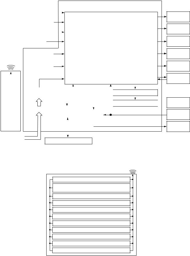
7. CONTROL BLOCK DIAGRAM
|
|
|
|
|
|
|
|
Indoor Unit Control Panel |
|
|
|||||||||||
|
|
|
|
|
|
|
|
|
|
|
|
|
|
|
|
|
M.C.U. |
8 MHz |
|||
|
Heat Exchanger Sensor (TCJ) |
|
|
|
Functions |
|
|
||||||||||||||
|
|
|
|
|
|
|
|
|
|
|
|||||||||||
|
|
|
|
|
|
|
|
|
|
|
|||||||||||
|
|
|
|
|
|
|
|
|
|
|
|
|
|
|
|
|
|
||||
|
|
|
|
|
|
|
|
|
|
|
|
|
|
|
|
|
|
||||
|
|
|
|
|
|
|
|
|
|
|
• |
Louver Control |
|
|
|||||||
|
Heat Exchanger Sensor (TC) |
|
|
|
|
|
|||||||||||||||
|
|
|
|
|
|
|
|
|
|
|
|
|
|
|
|||||||
|
|
|
|
|
|
|
|
|
|
|
• 3-minute Delay at Restart for Compressor |
||||||||||
|
|
|
|
|
|
|
|
|
|
|
|||||||||||
|
|
Temperature Sensor |
|
|
|
||||||||||||||||
|
|
|
|
|
• |
Motor Revolution Control |
|
|
|||||||||||||
|
|
|
|
|
|
|
|
|
|
|
|
|
|||||||||
|
|
|
|
|
|
|
|
|
|
|
|
|
|||||||||
Infrared Rays Signal Receiver |
|
|
|
|
|
|
|
|
|||||||||||||
|
|
|
|
|
|
|
|
|
|
|
|
|
|
|
|||||||
|
|
|
|
|
|
|
|
|
|
|
• |
Processing |
|
|
|||||||
|
|
|
|
|
|
|
|
|
|
|
|
|
|||||||||
|
|
|
|
|
|
|
|
|
|
|
|
(Temperature Processing) |
|
|
|||||||
|
|
|
|
Initiallizing Circuit |
|
|
|
|
|
|
|||||||||||
|
|
|
|
|
|
|
|
|
|
|
|
|
|
|
|
|
|
||||
|
Infrared |
|
|
|
|
|
|
|
|
• |
Timer |
|
|
|
|
|
|
|
|||
|
|
|
|
|
|
|
|
|
|
|
|
|
|
|
|
||||||
|
Rays |
|
|
|
|
|
|
|
|
|
|
|
|
|
|
|
|||||
|
|
Clock Frequence |
|
|
|
|
|
|
|
||||||||||||
|
|
|
|
|
|
|
|
|
|
|
|
|
|
|
|
||||||
|
|
|
|
|
|
|
|
|
|
|
|
|
|
|
|
|
|
||||
|
|
36.7 kHz |
|
Oscillator Circuit |
|
|
|
• |
Drain Pump ON/OFF |
|
|
||||||||||
|
|
|
|
|
|
|
|
|
|
|
|
|
|||||||||
|
|
|
|
|
|
|
|
|
|
|
• |
Serial Signal Communication |
|
|
|||||||
|
|
|
|
|
|
|
|
|
|
|
|
|
|||||||||
|
|
|
|
|
|
|
|
|
|
|
|
|
|||||||||
|
|
|
|
|
|
|
|
|
|
|
|
|
|
|
|
|
|
|
|
|
|
|
|
|
|
|
|
|
|
|
|
|
|
|
|
|
|
|
|
|
|
|
|
|
|
|
|
Power Supply |
|
|
|
|
|
|
|
|
|
|
|
|
Louver ON/OFF Signal |
||||
|
|
|
|
|
|
|
|
|
|
|
|
|
|
|
|||||||
|
Remote |
Circuit |
|
|
|
|
|
|
|
|
|
|
|
|
|
||||||
|
|
|
|
|
|
|
|
|
|
|
|
|
|
|
|
||||||
|
|
|
|
|
|
|
|
|
|
|
|
|
|
|
|
|
|
|
|||
|
Control |
|
|
|
|
|
|
|
|
|
|
|
|
|
|
|
|
Louver Driver |
|||
|
|
|
|
|
|
|
|
|
|
|
|
|
|
|
|
||||||
|
|
|
|
|
|
|
|
|
|
|
|
|
|
|
|
|
|
|
|
||
|
|
|
|
|
|
|
|
|
|
|
|
|
|
|
|
|
|
|
|
|
|
|
|
|
|
Noise Filter |
|
|
Serial Signal |
|
|
|
|
|
|
|
|
|
|||||
|
|
|
|
|
|
|
|
|
|
|
|
|
|
||||||||
|
|
|
|
|
|
|
|
Transmitter/ |
|
|
Relay |
|
|
|
|
||||||
|
|
|
|
|
|
|
|
|
|
|
|
|
|
|
|||||||
|
|
|
|
|
|
|
|
Receiver |
|
|
RY401 |
|
|
|
|
|
|||||
|
|
|
|
|
|
|
|
|
|
|
|
|
|
|
|||||||
|
|
|
|
|
|
|
|
|
|
|
|
|
|
|
|
|
|
|
|||
|
|
|
|
|
|
|
|
|
|
|
|
|
|
|
|
|
|
|
|
|
|
|
|
|
|
|
|
|
|
|
|
|
|
|
|
|
|
|
|
|
|
|
|
From Outdoor Unit
Serial Signal Communication
Hi POWER
Display
FILTER Sign
Display
PRE DEF.
Sign Display
TIMER
Display
OPERATION
Display
Indoor Fan
Motor

 Louver Motor
Float
Switch
Drain
Pump
REMOTE CONTROL
Infrared Rays
Remote Control
Operation (START/STOP)
Operation Mode Selection
AUTO, COOL, DRY, HEAT, FAN ONLY
Temperature Setting
Fan Speed Selection
ON TIMER Setting
OFF TIMER Setting
Louver Auto Swing
Louver Direction Setting
ECO
Hi power
Filter Reset
Ð 21 Ð
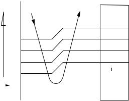
8. OPERATION DESCRIPTION
8-1. When power supply is reset
(1)Distinction of outdoor units
When the power supply is reset, the outdoors are distinguished, and control is exchanged according to the distinguished result.
(2)Setting of the indoor fan speed
Based on EEPROM data, rspeed of the indoor fan is selected.
Remarks: Air speed
8-2. Operation mode selection
(1)Based on the operation mode selecting command from the remote control, the operation mode is selected.
|
Table 8-2-1 |
|
|
|
|
Remote control |
Outline of control |
|
command |
||
|
||
|
|
|
STOP |
Air conditioner stops. |
|
|
|
|
FAN |
Fan operation |
|
|
|
|
COOL |
Cooling operation |
|
|
|
|
DRY |
Dry operation |
|
|
|
|
HEAT |
Heating operation |
|
|
|
|
AUTO |
Automatic operation |
|
|
|
(2)Automatic Operation
•The air conditioner selects and operates in one of the operating modes of cooling, heating or fan only, depending on the room temperature.
•If the AUTO mode is uncomfortable, you can select the desired conditions manually.
8-3. Air volume control
(1)Operation with [HIGH (H)], [MED (M)], [LOW (L)], or [AUTO] mode is performed by the command from the remote control.
(2)When [FAN] button is set to AUTO, the indoor fan motor operates as shown in Fig. 8-3-1, Fig. 8-3-2 and Table 8-3-1.
<COOL>
temp.) |
|
°C |
||
+3 |
|
|||
|
|
|||
(Preset |
|
M+ |
||
+2.5 |
|
|||
|
|
|||
|
*1 |
|||
− |
+2 |
|
||
*1 |
||||
temp.) |
||||
*1 |
||||
|
+1.5 |
|
||
(Room |
+1 |
|
||
+0.5 |
|
|||
|
||||
|
|
|||
Preset |
|
0 |
|
|
|
|
|||
temp. |
−0.5 |
|||
|
||||
NOTE :
*1: The values marked with *1 are calculated and controlled by the difference in motor speed between M+ and LÐ.
Fig. 8-3-1
|
|
Table 8-2-2 |
|
|
|
|
|
Room temperature in operation |
|
|
Operating condition |
|
|
|
|
The set temperature +1¡C or higher |
Cooling |
|
Performs the cooling operation at a temperature 1¡C |
(in case that the room is hot) |
operation |
|
higher than the setting. |
|
|
|
|
The set temperature Ð1¡C to +1¡C |
Fan only |
|
Performs the fan only operation (low speed) while |
|
operation |
|
monitoring the room temperature. When the room |
|
|
|
temperature changes, the air conditioner will select the |
|
|
|
cooling or heating mode. |
|
|
|
|
The set temperature Ð1¡C or lower |
Heating |
|
Performs the heating operation at a temperature 1¡C |
(in case that the room is cold) |
operation |
|
lower than the setting. |
|
|
|
|
Ð 22 Ð

<HEAT>
Preset |
°C |
|
||
|
0 |
L |
||
temp. |
−0.5 |
|
||
temp.) |
−1 |
*1 |
||
−2 |
||||
|
−1.5 |
*2 |
||
|
|
|
||
(Preset |
|
|
M+ |
|
− |
|
|
|
|
temp.) |
−5.0 |
|
||
(Room |
−5.5 |
H |
||
[FAN AUTO] |
||||
|
||||
|
|
|||
NOTE :
*1, *2 : The values marked with *1 and *2 are calculated and controlled by the difference in motor speed between M+ and L.
8-4. Cool air discharge preventive control
In heating operation, the indoor heat exchanger restricts revolving speed of the fan motor to prevent a cold draft. The upper limit of the revolving speed is shown in Fig. 8-4-1 and Table 8-4-1.
|
|
|
|
Manual |
|
|
|
AUTO |
(One of |
|
46 |
34 |
5 steps) |
|
|
45 |
33 |
|
|
|
|
|
*4 |
L−H |
|
33 |
21 |
|
|
|
|
(Up to |
||
|
32 |
20 |
|
|
|
|
setting |
||
|
|
|
|
|
|
|
|
SUL*3 |
speed) |
*2 |
A+4 |
A+4 |
SUL*1 |
|
|
A−8 |
A−8 |
|
|
|
Stop |
|
||
|
|
|
|
|
|
*6 |
*5 |
|
|
|
|
|
|
|
Fig. 8-3-2
Table 8-3-1
|
|
RAV-SM560XT-E |
RAV-SM800XT-E |
|||
MODEL |
|
|
|
|
||
Motor speed |
Air flow level |
Motor speed |
Air flow level |
|||
|
|
(rpm) |
|
(m3/h) |
(rpm) |
(m3/h) |
Cooling |
HIGH |
1060 |
|
800 |
1190 |
900 |
|
|
|
|
|
|
|
and |
MED |
950 |
|
690 |
1010 |
750 |
|
|
|
|
|
|
|
Fan only |
LOW |
800 |
|
580 |
850 |
650 |
|
HIGH |
1120 |
|
830 |
1300 |
980 |
Heating |
MED |
970 |
|
730 |
1070 |
800 |
|
LOW |
820 |
|
600 |
860 |
650 |
|
|
|
|
|
|
|
|
|
LOW+ |
= |
LOW+MED |
|
|
|
|
|
|
2 |
|
|
|
|
MED+ |
= MED+HIGH |
|
||
|
|
|
|
2 |
|
|
NOTES :
*1: The fan stops for 2 minutes after thermostat-OFF.
*2: A is 24°C when the preset temperature is 24°C or more and A is the preset temperature when it is under 24°C.
*3: SUL means Super Ultra Low.
*4: Calculated from difference in motor speed between SUL and HIGH.
Fig. 8-4-1 Cold draft preventing control
*5 and *6:
Table 8-4-1
Fan |
*5 |
|
*6 |
|
speed |
|
Starting period |
|
Stabilized period |
|
|
|
|
|
AUTO |
• |
Up until 12 minutes |
• |
From 12 to 25 minutes |
|
|
passed after starting |
|
passed after starting |
|
• |
the unit |
|
the unit and room |
|
From 12 to 25 minutes |
|
temperature is |
|
|
|
passed after starting |
|
between preset |
|
|
the unit and room |
|
temperature and 3°C |
|
|
temperature is 3°C |
|
lower than preset |
|
|
lower than preset |
|
temperature |
|
|
temperature |
• |
25 minutes or more |
|
|
|
|
passed after starting |
|
|
|
|
the unit |
Manual |
• |
Room temperature |
• |
Room temperature |
(L Ð H) |
|
< Preset temperature |
|
Preset temperature |
|
|
Ð4°C |
|
Ð3.5°C |
Ð 23 Ð
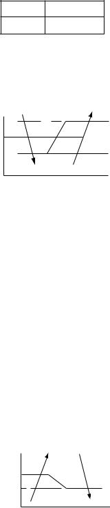
8-5. Freeze preventive control (Low temperature release)
The cooling operation (including Dry operation) is performed as follows based on the detected temperature of Tc sensor or Tcj sensor.
When [J] zone is detected for T1 minutes (Following figure), the commanded frequency is decreased from the real operation frequency. After then the commanded frequency changes every 2 minutes while operation is performed in [J] zone.
T1
Normal |
1 minute |
In [K] zone, time counting is interrupted and the operation is held.
When [I] zone is detected, the timer is cleared and the operation returns to the normal operation.
(°C) |
|
|
|
7 |
|
I |
A |
|
|||
6 |
|
|
K |
|
|
|
|
5 |
|
|
J |
|
|
||
|
|
|
Fig. 8-5-1
In heating operation, the freeze-preventive control works if 4-way valve is not exchanged and the condition is satisfied.
Remarks:
Tcj : Indoor heat exchanger sensor temperature
8-6. High-temp release control
The heating operation is performed as follows based on the detected temperature of Tc sensor.
•When [M] zone is detected, the commanded frequency is decreased from the real operation frequency. After then the commanded frequency changes every 30 seconds while operation is performed in [M] zone.
•In [N] zone, the commanded frequency is held.
•When [L] zone is detected, the commanded frequency is returned to the original value by approx. 6Hz every 60 seconds.
8-7. Louver control
(1)Vertical air flow louver
Position of veritcal air flow louver is automatically controlled according to the operation mode. Besides, position of vertical air flow louver can be arbitrarily set by pressing [FIX] button.
The louver position which is set by [FIX] button is stored in the microcomputer, and the louver is automatically set at the stored position for the next operation.
(2)Swing
If [SWING] button is pressed when the indoor unit is in operation, the vertical air flow louver starts swinging. When [SWING] button is pressed, it stops swinging.
8-8. Filter sign display
(1)The operation time of the indoor fan is calculated, the filter lamp (Orange) on the display part of the main unit goes on when the specified time (240H) has passed. When a wired remote controller is connected, the filter reset signal is sent to the remote controller, and also it is displayed on LCD of the wired remote control.
(2)When the filter reset signal has been received from the wired remote control after [FILTER] lamp has gone on or when the filter check button (Temporary button) is pushed, time of the calculation timer is cleared. In this case, the measurement time is reset if the specified time has passed, and display on LCD and the display on the main unit disappear.
Remarks:
[FILTER] goes on
Tc (°C) |
M |
||
55 A |
|
|
|
|
|
|
|
|
N |
||
52 |
|
|
|
48 B
L
Fig. 8-6-1
Ð 24 Ð

8-9. Auto Restart Function
The indoor unit is equipped with an automatic restarting function which allows the unit to restart operating with the set operating conditions in the event of power supply being accidentally shut down. The operation will resume without warning three minutes after power is restored.
This function is not set to work when shipped from the factory. Therefore it is necessary to set it to work.
When the unit is on standby (Not operating)
8-9-1. How to set auto restart function
To set the auto restart function, proceed as follows: The power supply to the unit must be on; the function will not set if the power is off.
Push the [TEMPORARY] button located in the center of the front panel continuously for three seconds. The unit receives the signal and beeps three times. The unit then restarts operating automatically in the event of power supply being accidentally shut down.
Operation
Push [TEMPORARY] button for more than three seconds.
|
0 |
Hi POWER FILTER PRE.D |
3S |
TEMPORARY button
When the unit is in operation
Operation
Push [TEMPORARY] button for more than three seconds.
|
0 |
Hi POWER FILTER PRE.D |
3S |
TEMPORARY button
|
|
Motions |
The unit is on standby. |
|
|
→ |
|
|
The unit starts to operate. |
The green lamp is on. |
|
→ |
After approx. three seconds, |
|
The unit beeps three times |
The lamp changes from |
|
and continues to operate. |
green to orange. |
|
If the unit is not required to operate at this time, push [TEMPORARY] button once more or use the remote control to turn it off.
|
|
Motions |
The unit is in operation. |
The green lamp is on. |
|
→ |
|
|
The unit stops operating. |
The green lamp is turned off. |
|
→ |
After approx. three seconds, |
|
The unit beeps three times.
If the unit is required to operate at this time, push [TEMPORARY] button once more or use the remote control to turn it on.
• |
While this function is being set, if the unit is in |
• While the filter check lamp is on, the |
• |
operation, the orange lamp is on. |
TEMPORARY button has the function of filter |
This function can not be set if the timer operation |
reset button. |
|
|
has been selected. |
|
•When the unit is turned on by this function, the louver will not swing even though it was swinging automatically before shutting down.
Ð 25 Ð
 Loading...