


FILE NO. SVM-12004
SERVICE MANUAL
AIR-CONDITIONER
SPLIT TYPE
INDOOR UNIT
High Wall Type
RAV-SM566KRT-E, RAV-SM806KRT-E RAV-SM566KRT-TR, RAV-SM806KRT-TR
R410A

FILE NO. SVM-12004
Adoption of New Refrigerant
This Air Conditioner is a new type which adopts a new refrigerant HFC (R410A) instead of the conventional refrigerant R22 in order to prevent destruction of the ozone layer.
CONTENTS
SAFETY CAUTION ............................................................................................ |
3 |
||
1. |
SPECIFICATIONS .................................................................................... |
12 |
|
|
1-1. High Wall Type ................................................................................................................. |
12 |
|
2. |
CONSTRUCTION VIEWS (EXTERNAL VIEWS)....................................... |
13 |
|
3. |
SYSTEMATIC REFRIGERATING CYCLE DIAGRAM .............................. |
15 |
|
4. |
WIRING DIAGRAM ................................................................................... |
16 |
|
5. |
SPECIFICATIONS OF ELECTRICAL PARTS .......................................... |
17 |
|
6. |
REFRIGERANT R410A ............................................................................ |
18 |
|
|
6-1. |
Safety During Installation/Servicing ............................................................................. |
18 |
|
6-2. |
Refrigerant Piping Installation .................................................................................... |
18 |
|
6-3. |
Tools ................................................................................................................................ |
22 |
|
6-4. |
Recharging of Refrigerant ............................................................................................. |
23 |
|
6-5. |
Brazing of Pipes ............................................................................................................. |
24 |
7. |
INDOOR CONTROL CIRCUIT .................................................................. |
26 |
|
|
7-1. |
Indoor Controller Block Diagram ................................................................................. |
26 |
|
7-2. Control Specifications .................................................................................................. |
28 |
|
|
7-3. Indoor Print Circuit Board (High Wall Type) ................................................................. |
40 |
|
8. |
TROUBLESHOOTING .............................................................................. |
42 |
|
|
8-1. |
Summary of Troubleshooting ....................................................................................... |
42 |
|
8-2. |
Troubleshooting ............................................................................................................ |
44 |
9. |
REPLACEMENT OF SERVICE P.C. BOARD............................................ |
60 |
|
10. |
SETUP AT LOCAL SITE AND OTHERS .................................................. |
66 |
|
11. |
ADDRESS SETUP.................................................................................... |
83 |
|
|
11-1. |
Address Setup Procedure ............................................................................................. |
83 |
|
11-2. |
Address Setup & Group/Twin/Triple Control ............................................................... |
84 |
|
11-3. |
Address Setting ............................................................................................................. |
86 |
12. |
DETACHMENTS ....................................................................................... |
88 |
|
13. |
EXPLODED VIEWS AND PARTS LIST .................................................... |
95 |
|
14. APPENDIX (Lite-vision plus remote controller Installation manual) ..... |
97 |
||
– 2 –
Original instruction
FILE NO. SVM-12004
Generic Denomination: Air Conditioner
Definition of Qualified Installer or Qualified Service Person
Agent |
Qualifications and knowledge which the agent must have |
|
|
|
|
|
|
– 3 –
FILE NO. SVM-12004
Definition of Protective Gear
Work undertaken |
Protective gear worn |
|
|
|
|
|
|
|
|
|
|
|
|
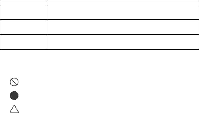
[Explanation of indications]
Indication |
Explanation |
 DANGER
 WARNING
 CAUTION
[Explanation of illustrated marks]
Mark |
Explanation |
|
|
|
|
|
|
|
|
– 4 –
FILE NO. SVM-12004
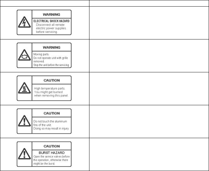
Warning Indications on the Air Conditioner Unit [Confirmation of warning label on the main unit]
Warning indication |
Description |
WARNING
ELECTRICAL SHOCK HAZARD
WARNING
CAUTION
CAUTION
CAUTION
BURST HAZARD
– 5 –

FILE NO. SVM-12004
Precautions for safety
 DANGER
– 6 –

FILE NO. SVM-12004
 WARNING
– 7 –

FILE NO. SVM-12004
– 8 –

FILE NO. SVM-12004
Ω
– 9 –

FILE NO. SVM-12004
Explanations given to user
Relocation
– 10 –
FILE NO. SVM-12004
Declaration of Conformity
NOTE
Specifications
Model |
Sound power level (dBA) |
Weight (kg) |
||
|
|
|
||
Cooling |
Heating |
Main unit (Ceiling panel) |
||
|
||||
|
|
|
|
|
|
|
|
|
|
|
|
|
|
|
|
|
|
|
|
|
|
|
|
|
|
|
|
|
|
|
|
|
|
|
|
|
|
|
|
|
|
|
|
|
– 11 –
FILE NO. SVM-12004
1. SPECIFICATIONS
1-1. High-wall type
Model |
Indoor unit |
RAV-SM |
566KRT-E(TR) |
806KRT-E(TR) |
566KRT-E(TR) |
806KRT-E(TR) |
|||
|
|
|
|
|
|
|
|
||
Outdoor unit |
RAV- |
SP564AT(Z)(ZG)-E |
SP804AT(Z)(ZG)-E |
SM563AT-E |
SM803AT-E |
||||
|
|||||||||
|
|
|
|
|
|
|
|
|
|
Cooling Capacity |
(kW) |
|
|
5.0 |
7.1 |
5.0 |
6.7 |
||
|
|
|
|
|
|
|
|
|
|
Heating Capacity |
(kW) |
|
|
5.6 |
8.0 |
5.6 |
8.0 |
||
|
|
|
|
|
|
|
|
|
|
Power Supply |
|
|
|
|
|
1 phase 230V (220-240V) 50Hz |
|
||
|
|
|
|
|
|
|
|
||
|
|
Running current |
(A) |
6.74-6.18 |
10.71-9.82 |
7.77-7.12 |
11.18-10.25 |
||
|
|
|
|
|
|
|
|||
|
|
Power consumption (kW) |
1.44 |
2.21 |
1.66 |
2.37 |
|||
|
|
|
|
|
|
|
|
|
|
|
Cooling |
Power factor |
|
(%) |
99 |
96 |
98 |
99 |
|
|
|
|
|
|
|
|
|
||
|
EER |
|
|
3.47 |
3.21 |
3.01 |
2.83 |
||
|
|
|
|
||||||
|
|
|
|
|
|
|
|||
|
|
Energy efficiency class |
A |
A |
B |
C |
|||
|
|
|
|
|
|
|
|
||
Electrical |
|
Energy rating |
|
- |
- |
- |
- |
||
|
|
|
|
|
|
|
|
||
|
Running current |
(A) |
6.98-6.40 |
11.02-10.10 |
7.60-6.96 |
11.88-10.89 |
|||
Characteristics |
|
||||||||
|
|
|
|
|
|
|
|
||
|
Power consumption (kW) |
1.50 |
2.34 |
1.64 |
2.49 |
||||
|
|
||||||||
|
|
|
|
|
|
|
|
|
|
|
Heating |
Power factor |
|
(%) |
99 |
96 |
98 |
99 |
|
|
|
|
|
|
|
|
|
||
|
COP |
|
|
3.73 |
3.42 |
3.41 |
3.21 |
||
|
|
|
|
||||||
|
|
|
|
|
|
|
|||
|
|
Energy efficiency class |
A |
B |
B |
C |
|||
|
|
|
|
|
|
|
|
||
|
|
Energy rating |
|
- |
- |
- |
- |
||
|
|
|
|
|
|
|
|
|
|
|
Maximum current |
|
|
(A) |
13.4 |
20.4 |
12.3 |
14.4 |
|
|
|
|
|
|
|
|
|
|
|
Appearance |
Main unit |
|
|
|
|
Moon white |
|
||
|
|
|
|
|
|
|
|
|
|
|
|
Height |
|
(mm) |
320 |
320 |
320 |
320 |
|
|
|
|
|
|
|
|
|
|
|
Outer dimension |
Main unit |
Width |
|
(mm) |
1050 |
1050 |
1050 |
1050 |
|
|
|
|
|
|
|
|
|
|
|
|
|
Depth |
|
(mm) |
228 |
228 |
228 |
228 |
|
|
|
|
|
|
|
|
|
|
|
Total weight |
Main unit |
|
|
(kg) |
12 |
12 |
12 |
12 |
|
|
|
|
|
|
|
|
|
|
|
Heat exchanger |
|
|
|
|
|
Finned tube |
|
||
|
|
|
|
|
|
|
|
||
|
Fan |
|
|
|
|
Cross flow fan |
|
||
|
|
|
|
|
|
|
|
||
Fan unit |
Standard air flow |
H/M/L |
(m3/min.) |
14.0/12.5/11.0 |
17.0/12.5/11.0 |
14.0/12.5/11.0 |
17.0/12.5/11.0 |
||
|
|
|
|
|
|
|
|
|
|
|
Motor |
|
|
(W) |
30 |
30 |
30 |
30 |
|
|
|
|
|
|
|
|
|
|
|
Air filter |
|
|
|
|
|
Standard filter attached |
|
||
|
|
|
|
|
|
|
|||
Controller (packed with inndoor unit) |
|
|
|
|
WH-L11SE |
|
|||
|
|
|
|
|
|
|
|||
Controller (sold separately) |
|
|
|
|
RBC-AMT32E,AS21E2,AMS41E,AMS51E |
|
|||
|
|
|
|
|
|
|
|
||
Sound pressure level |
H/M/L |
|
(dB A) |
42/39/36 |
47/41/36 |
42/39/36 |
47/41/36 |
||
|
|
|
|
|
|
|
|
|
|
Sound power level |
|
H/M/L |
|
(dB A) |
57/54/51 |
62/56/51 |
57/54/51 |
62/56/51 |
|
|
|
|
|
|
|
|
|
|
|
|
|
Gas side |
|
(mm) |
12.7 |
15.9 |
12.7 |
15.9 |
|
|
|
|
|
|
|
|
|
|
|
Connecting pipe |
|
Liquid side |
|
(mm) |
6.4 |
9.5 |
6.4 |
9.5 |
|
|
|
|
|
|
|
|
|
|
|
|
|
Drain port |
|
(mm) |
|
VP16 |
|
||
|
|
|
|
|
|
|
|
||
|
|
|
|
|
|
|
IEC Standard AS Standard |
||
– 12 –
FILE NO. SVM-12004
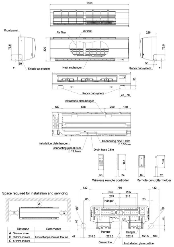
2. CONSTRUCTION VIEWS (EXTERNAL VIEWS)
2-1. 4-Way Air Discharge Cassette Type
RAV-SM566KRT-E(TR)
– 13 –

FILE NO. SVM-12004
RAV-SM806KRT-E(TR)
– 14 –
FILE NO. SVM-12004
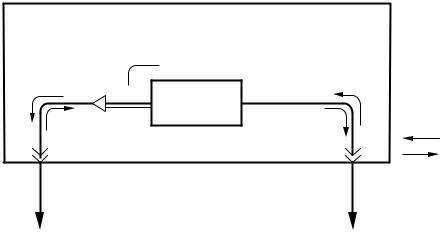
3. SYSTEMATIC REFRIGERATING CYCLE DIAGRAM
High Wall Type
• Single type (Combination of 1 indoor unit and 1 outdoor unit)
TCJ sensor
 Air heat exchanger
TC sensor 
Dimension table
Indoor unit |
Outer diameter of refrigerant pipe (In (mm)) |
||
|
|
||
Gas side ØA |
Liquid side ØB |
||
|
|||
|
|
|
|
SM56 type |
12.7 |
6.4 |
|
|
|
|
|
SM80 type |
15.9 |
9.5 |
|
|
|
|
|
– 15 –
– 16 –
|
|
|
|
|
|
|
|
|
|
|
|
|
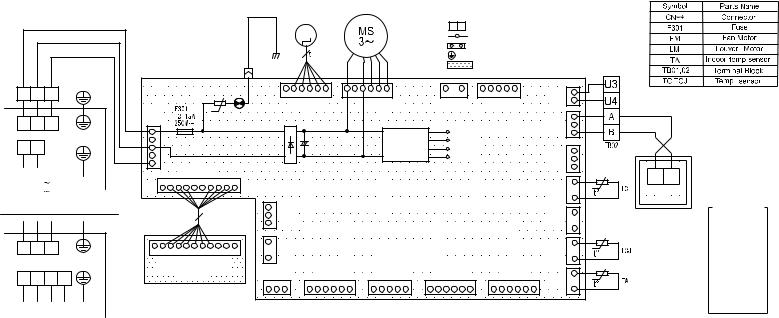
BLK |
|
|
|
LM |
|
|
|
|
|
|
|
|
|
|
|
|
|
|
|
|
|
|
|
|
|
|
|
|
|
|
|
|
|
|
|
|
|
|
|
|
|
|
|
|
|
|
|
|
|
|
|
|
|
|
|
|
|
|
|
|
|
|
|
|
|
|
|
|
|
|
|
|
|
|
|
|
|
|
||
|
|
|
|
|
|
|
|
|
|
|
|
|
|
|
|
|
M |
|
|
|
|
|
|
|
|
|
|
|
|
|
|
|
|
|
|
|
|
|
|
|
|
|
|
|
|
|
|
|
|
|
|
|
|
|
|
|
|
|
|
|
|
|
|
|
|
|
|
|
|
|
|
|
|
FM |
|
|
|
|
|
|
|
|
|
|
|
|
|
|
|
|
|
|
|
|
|
Earth |
|
|
|
|
|
|
|
|
|
CN22 |
|
|
|
|
|
|
|
|
|
|
|
|
|
|
|
|
|
|
|
|
|
|
|
|
|
|
|
|
|
|
|
|
|
|
|
|
|
|
|
|
|
|
|
|
|
|
|
|
|
|
|
|
|
|
|
|
|
|
|
|
|
|
|
|
|
|
|
|
|
|
|
|
|
|
|
|
|
|
BLU |
|
|
|
|
SCREW |
|
|
|
|
|
|
|
|
|
|
|
|
|
|
|
|
|
|
|
|
|
|
|
|
|
|
|
|
|
|
|
|
|
|
|
|
|
|
|
|
|
|
|
|
|
|
|
|
|
|
|
|
|
|
|
|
|
|
|
|
|
|
|
|
|
|
|
|
|
|
|
|
|
|
|
|
|
|
|
|
|
|
|
|
|
|
|
|
|
|
|
TB01 |
|
|
|
|
|
|
|
|
|
|
|
|
|
|
1 |
2 |
3 |
4 |
5 |
6 |
|
|
1 |
3 |
4 |
5 |
6 |
|
|
|
|
1 |
|
2 |
|
1 |
2 |
3 |
4 |
5 |
|
|
CN40 |
1 |
BLU |
|
|
|
|
|
|
|
|
|
|
|
|
|
|
|
|
|
CN33(WHI) |
|
|
|
CN210(WHI) |
|
|
|
CN44(BRW) |
|
CN50(WHI) |
|
|
(BLU) 2 |
|
||||||||||||||||
|
|
|
|
|
|
|
|
|
|
|
|
|
|
|
|
|
|
|
|
|
|
|
|
|
|
|
||||||||||||||||||||
|
|
|
CN67 |
|
|
|
|
|
U |
|
|
|
|
|
|
|
|
|
|
|
|
|
|
|
|
|
|
|
|
|
|
|
|
|
|
|
|
|
|
|
|
1 |
BLK |
|
||
|
|
|
(BLK) |
|
|
|
|
|
|
|
|
|
|
|
+ |
|
|
|
|
|
|
|
|
|
|
|
|
|
|
|
|
|
|
|
|
|
|
|
|
CN41 |
|
|
||||
|
|
|
RED |
1 |
|
|
|
|
|
|
|
|
|
|
|
|
|
|
|
|
|
|
|
|
|
|
|
|
|
|
|
|
|
|
|
|
|
|
|
|
|
(BLU) |
2 |
BLK |
|
|
|
|
Earth |
|
|
|
|
|
|
|
|
|
|
|
|
|
|
|
|
|
|
|
|
|
|
|
|
|
|
|
|
|
|
|
|
|
|
|
|
|
|
|
|||||
|
|
|
|
|
|
|
|
|
|
|
|
|
|
|
|
|
|
|
|
|
|
|
|
|
POWER |
|
|
|
|
|
|
|
|
|
|
|
|
|
3 |
|
||||||
|
|
SCREW |
WHI |
|
|
|
|
|
|
|
|
|
|
|
|
|
|
+ |
|
|
|
|
|
|
|
|
|
|
|
|
|
|
|
|
|
|
|
|
|
|
|
|
|
|
||
|
|
3 |
|
|
|
|
|
|
|
|
|
|
|
|
|
- |
|
|
|
|
|
|
|
|
|
SUPPLY |
|
|
|
|
|
|
|
|
|
|
|
|
|
|
|
|
|
|||
|
|
|
|
|
|
|
|
|
|
|
|
|
|
|
|
|
|
|
|
|
|
|
|
|
|
|
CIRCUIT |
|
|
|
|
|
|
|
|
|
|
|
|
|
CN100 |
1 |
|
|
||
|
|
|
BLK |
5 |
|
|
|
|
|
|
|
|
|
|
|
|
|
- |
|
|
|
|
|
|
|
|
|
|
|
|
|
|
|
|
|
|
|
|
|
|
|
|
2 |
|
|
|
|
|
|
|
|
|
|
|
|
|
|
|
|
|
|
|
|
|
|
|
|
|
|
|
|
|
|
|
|
|
|
|
|
|
|
|
|
|
|
|
|
|
|
(BRW) |
3 |
|
|
POWER SUPPLY |
|
|
|
|
|
CN213(WHI) |
|
|
|
|
|
|
|
|
|
|
|
|
|
|
|
|
|
|
|
|
|
|
|
|
|
|
|
|
|
|
|
|
|
1 |
A |
B |
||||
220-240V 1 |
50Hz |
|
1 |
2 |
3 |
4 |
5 |
6 |
7 |
8 |
9 |
10 |
|
|
|
|
|
|
|
|
|
|
|
|
|
|
|
|
|
|
|
|
|
|
|
|
|
|
|
|
|
CN101 |
|
|
||
220V |
1 |
60Hz |
|
|
|
|
|
|
|
|
|
|
|
|
|
|
|
|
|
|
|
|
|
|
|
|
|
|
|
|
|
|
|
|
|
|
|
|
|
|
|
|
|
|
|
|
|
|
|
|
|
|
|
|
|
|
|
|
|
|
|
|
|
|
|
|
|
|
|
|
|
|
|
|
|
|
|
|
|
|
|
|
|
|
|
|
(BLU) 2 |
|
|
||||
OUTDOOR UNIT(SINGLE PHASE) |
|
|
|
|
|
|
|
|
|
|
|
|
|
|
|
|
|
|
|
|
|
|
|
|
|
|
|
|
|
|
|
|
|
|
|
|
|
|
|
|
|
|
||||
|
|
|
|
|
|
|
|
|
|
|
1 |
|
|
|
|
|
|
|
|
|
|
|
|
|
|
|
|
|
|
|
|
|
|
|
|
|
|
|
|
|
|
|
|
|||
|
|
|
|
|
|
|
|
|
|
|
|
|
|
2 |
CN309 |
|
|
|
|
|
|
|
|
|
|
|
|
|
|
|
|
|
|
|
|
|
|
|
|
|
|
CN103 |
1 |
WIRED REMOTE |
||
|
|
|
|
|
|
|
|
|
|
|
|
|
|
|
|
|
|
|
|
|
|
|
|
|
|
|
|
|
|
|
|
|
|
|
|
|
|
|
|
|
||||||
|
|
|
|
|
|
|
|
|
|
|
|
|
|
|
(YEL) |
|
|
|
|
|
|
|
|
|
|
|
|
|
|
|
|
|
|
|
|
|
|
|
|
|
|
|
CONTROLLER |
|||
|
|
|
|
|
|
|
|
|
|
|
|
|
|
3 |
Control P.C. board for indoor unit |
|
|
(GRN) |
2 |
|||||||||||||||||||||||||||
|
|
|
|
|
|
|
|
|
|
|
|
|
|
|
|
|
|
|
|
|
||||||||||||||||||||||||||
|
|
|
|
|
|
|
|
|
|
|
|
|
|
|
|
|
|
|
|
|
|
|
||||||||||||||||||||||||
|
|
Earth |
|
|
|
|
|
|
|
|
|
|
|
1 |
CN32 |
|
|
|
|
|
|
|
|
(MCC-1510) |
|
|
|
|
|
|
|
|
|
|
(YEL) |
1 |
|
|
||||||||
|
|
|
|
|
|
|
|
|
|
|
|
|
2 |
(WHI) |
|
|
|
|
|
|
|
|
|
|
|
|
|
|
|
|
|
|
2 |
|
|
|||||||||||
|
|
|
1 |
2 |
3 |
4 |
5 |
6 |
7 |
8 |
9 |
10 11 |
|
|
|
|
|
|
|
|
|
|
|
|
|
|
|
|
|
|
|
|
|
|
|
|
|
|
|
|
|
CN102 |
|
|
|
|
|
|
|
|
|
|
|
|
|
|
|
|
|
|
|
|
|
|
|
|
|
|
|
|
|
|
|
|
|
|
|
|
|
|
|
|
|||||||||||
|
|
SCREW |
|
INFRARED RAYS RECEIVE |
|
|
|
|
|
|
|
|
|
|
|
|
|
|
|
|
|
|
|
|
|
|
|
|
|
|
|
|
|
|
|
|
|
|
||||||||
|
|
|
AND INDICATION PARTS |
|
|
|
|
|
|
|
|
|
|
|
|
|
|
|
|
|
|
|
|
|
|
|
|
|
|
|
|
|
|
|
1 |
|
|
|||||||||
|
|
|
|
|
|
(MCC-5044) |
|
|
CN80(GRN) |
|
|
|
CN82(BLU) |
|
|
|
CN81(BLK) |
|
CN61(YEL) |
|
|
|
CN60(WHI) |
|
CN104 |
|
|
|||||||||||||||||||
|
|
|
|
|
|
|
|
|
|
|
|
|
|
|
|
|
|
|
|
|
|
|||||||||||||||||||||||||
|
|
|
|
|
|
|
|
|
|
|
|
|
1 |
2 |
3 |
|
|
1 |
2 |
3 |
4 |
5 |
6 |
|
1 |
2 |
3 |
4 |
5 |
1 |
2 |
3 |
4 |
5 |
6 |
|
1 |
2 |
3 |
4 |
5 |
6 |
(WHI) 2 |
|
|
|
|
|
|
|
|
|
|
|
|
|
|
|
|
|
|
|
|
|
|
|
|
|
|
|
|
|
|
|
|
|
|
|
|
|
|
|
|
|
|
|
|
|
|
|
|
||
POWER SUPPLY |
|
|
|
|
|
|
|
|
|
|
|
PNL/EMG |
|
|
|
|
|
|
|
|
|
|
|
|
|
|
|
|
|
|
|
|
|
|
|
OPTION |
|
|
|
|
|
|||||
|
|
|
|
|
|
|
|
|
|
|
|
|
|
|
|
|
|
|
|
|
|
|
|
|
|
|
|
|
|
|
|
|
|
|
|
|
|
|
|
|
|
|
|
|
||
380-415V 3N 50Hz
50Hz
380V 3N 60Hz
60Hz
OUTDOOR UNIT (3-PHASE)
Type Wall High .1-4
DIAGRAM WIRING .4
12004-SVM .NO FILE
FILE NO. SVM-12004
5. SPECIFICATIONS OF ELECTRICAL PARTS
5-3. High Wall Type
No. |
Parts Name |
Type |
Specications |
|
|
|
|
1 |
Fan motor (for indoor) |
ICF-340-U30-1 |
Output (Rated) 30W, 340V DC |
ICF-340-30X |
|||
|
|
MF-340-30X |
|
2 |
Grille motor |
MP24Z3T |
Output (Rated) 1W, 16 poles DC |
|
|
|
|
3 |
Thermo. Sensor (TA sensor) |
318mm |
10kΩ at 25°C |
|
|
|
|
4 |
Heat exchanger sensor (TC sensor) |
Ø6,800mm |
10kΩ at 25°C |
|
|
|
|
5 |
Heat exchanger sensor (TCJ sensor) |
Ø6,800mm |
10kΩ at 25°C |
|
|
|
|
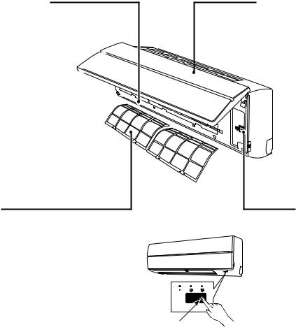
n Name of Each Part
Air outlet / Louver
Change the direction of the air to be discharged according to cool/heat mode.
Air inlet grille
Air in the room is sucked from here.
Air filter |
Earth screw |
Removes dirt or dust. |
Earth screws are provided |
(Provided in the air inlet grille) |
in the electric parts box. |
– 17 –
FILE NO. SVM-12004
6. REFRIGERANT R410A
This air conditioner adopts the new refrigerant HFC (R410A) which does not damage the ozone layer.
The working pressure of the new refrigerant R410A is 1.6 times higher than conventional refrigerant (R22). The refrigerating oil is also changed in accordance with change of refrigerant, so be careful that water, dust, and existing refrigerant or refrigerating oil are not entered in the refrigerant cycle of the air conditioner using the new refrigerant during installation work or servicing time.
The next section describes the precautions for air conditioner using the new refrigerant.
Conforming to contents of the next section together with the general cautions included in this manual, perform the correct and safe work.
6-1. SafetyDuringInstallation/Servicing
As R410A’s pressure is about 1.6 times higher than that of R22, improper installation/servicing may cause a serious trouble. By using tools and materials exclusive for R410A, it is necessary to carry out installation/servicing safely while taking the following precautions into consideration.
1.Never use refrigerant other than R410A in an air conditioner which is designed to operate with R410A. If other refrigerant than R410A is mixed, pressure in the refrigeration cycle becomes abnormally high, and it may cause personal injury, etc. by a rupture.
2.Confirm the used refrigerant name, and use tools and materials exclusive for the refrigerant R410A. The refrigerant name R410A is indicated on the visible place of the outdoor unit of the air conditioner using R410A as refrigerant.
To prevent mischarging, the diameter of the service port differs from that of R22.
3.If a refrigeration gas leakage occurs during installation/servicing, be sure to ventilate fully.
If the refrigerant gas comes into contact with fire, a poisonous gas may occur.
4.When installing or removing an air conditioner, do not allow air or moisture to remain in the refrigeration cycle.
Otherwise, pressure in the refrigeration cycle may become abnormally high so that a rupture or personal injury may be caused.
5.After completion of installation work, check to make sure that there is no refrigeration gas leakage. If the refrigerant gas leaks into the room, coming into contact with fire in the fandriven heater, space heater, etc., a poisonous gas may occur.
6.When an air conditioning system charged with a large volume of refrigerant is installed in a small room, it is necessary to exercise care so that, even when refrigerant leaks, its concentration does not exceed the marginal level.
If the refrigerant gas leakage occurs and its concentration exceeds the marginal level, an oxygen starvation accident may result.
7.Be sure to carry out installation or removal according to the installation manual.
Improper installation may cause refrigeration trouble, water leakage, electric shock, fire, etc.
8.Unauthorized modifications to the air conditioner may be dangerous.
If a breakdown occurs please call a qualified air conditioner technician or electrician.
Improper repair may result in water leakage, electric shock and fire, etc.
6-2. Refrigerant Piping Installation
6-2-1. Piping Materials and Joints Used
For the refrigerant piping installation, copper pipes and joints are mainly used. Copper pipes and joints suitable for the refrigerant must be chosen and installed. Furthermore, it is necessary to use clean copper pipes and joints whose interior surfaces are less affected by contaminants.
1.Copper Pipes
It is necessary to use seamless copper pipes which are made of either copper or copper alloy and it is desirable that the amount of residual oil is less than 40 mg/10 m.
Do not use copper pipes having a collapsed, deformed or discolored portion (especially on the interior surface).
Otherwise, the expansion valve or capillary tube may become blocked with contaminants.
As an air conditioner using R410A incurs pressure higher than when using R22, it is necessary to choose adequate materials.
Thicknesses of copper pipes used with R410A are as shown in Table 6-2-1.
Never use copper pipes thinner than 0.8 mm even when it is available on the market.
– 18 –
|
|
|
|
FILE NO. SVM-12004 |
|
Table 6-2-1 Thicknesses of annealed copper pipes |
|||
|
|
|
|
|
|
|
|
|
Thickness (mm) |
|
|
|
|
|
Nominal diameter |
|
Outer diameter (mm) |
R410A |
R22 |
|
|
|
|
|
1/4 |
6.35 |
0.80 |
0.80 |
|
|
|
|
|
|
3/8 |
9.52 |
0.80 |
0.80 |
|
|
|
|
|
|
1/2 |
12.70 |
0.80 |
0.80 |
|
|
|
|
|
|
5/8 |
15.88 |
1.00 |
1.00 |
|
|
|
|
|
|
2.Joints
For copper pipes, flare joints or socket joints are used. Prior to use, be sure to remove all contaminants.
a)Flare Joints
Flare joints used to connect the copper pipes cannot be used for pipings whose outer diameter exceeds 20 mm. In such a case, socket joints can be used.
Sizes of flare pipe ends, flare joint ends and flare nuts are as shown in Tables 6-2-3 to 6-2-6 below.
b)Socket Joints
Socket joints are such that they are brazed for connections, and used mainly for thick pipings whose diameter is larger than 20 mm.
Thicknesses of socket joints are as shown in Table 6-2-2.
Table 6-2-2 Minimum thicknesses of socket joints
Nominal diameter |
Reference outer diameter of |
Minimum joint thickness |
|
copper pipe jointed (mm) |
(mm) |
||
|
|||
|
|
|
|
1/4 |
6.35 |
0.50 |
|
|
|
|
|
3/8 |
9.52 |
0.60 |
|
|
|
|
|
1/2 |
12.70 |
0.70 |
|
|
|
|
|
5/8 |
15.88 |
0.80 |
|
|
|
|
6-2-2. Processing of Piping Materials
When performing the refrigerant piping installation, care should be taken to ensure that water or dust does not enter the pipe interior, that no other oil than lubricating oils used in the installed air-water heat pump is used, and that refrigerant does not leak.
When using lubricating oils in the piping processing, use such lubricating oils whose water content has been removed. When stored, be sure to seal the container with an airtight cap or any other cover.
1.Flare processing procedures and precautions
a)Cutting the Pipe
By means of a pipe cutter, slowly cut the pipe so that it is not deformed.
b)Removing Burrs and Chips
If the flared section has chips or burrs, refrigerant leakage may occur. Carefully remove all burrs and clean the cut surface before installation.
c)Insertion of Flare Nut
–19 –
FILE NO. SVM-12004
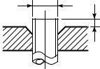
d) Flare Processing
Make certain that a clamp bar and copper pipe have been cleaned.
By means of the clamp bar, perform the flare processing correctly.
Use either a flare tool for R410A or conventional flare tool.
Flare processing dimensions differ according to the type of flare tool.
When using a conventional flare tool, be sure to secure “dimension A” by using a gauge for size adjustment.
ØD |
A |
Fig. 6-2-1 Flare processing dimensions
Table 6-2-3 Dimensions related to flare processing for R410A
|
Outer |
|
|
|
A (mm) |
|
|
|
|
|
|
|
|
||
Nominal |
Thickness |
|
|
|
|||
diameter |
Flare tool for R410A |
Conventional flare tool |
|||||
diameter |
(mm) |
||||||
(mm) |
|
|
|||||
|
|
|
clutch type |
Clutch type |
Wing nut type |
||
|
|
|
|
||||
|
|
|
|
|
|||
|
|
|
|
|
|
|
|
1/4 |
6.35 |
0.8 |
|
0 to 0.5 |
1.0 to 1.5 |
1.5 to 2.0 |
|
|
|
|
|
|
|
|
|
3/8 |
9.52 |
0.8 |
|
0 to 0.5 |
1.0 to 1.5 |
1.5 to 2.0 |
|
|
|
|
|
|
|
|
|
1/2 |
12.70 |
0.8 |
|
0 to 0.5 |
1.0 to 1.5 |
2.0 to 2.5 |
|
|
|
|
|
|
|
|
|
5/8 |
15.88 |
1.0 |
|
0 to 0.5 |
1.0 to 1.5 |
2.0 to 2.5 |
|
|
|
|
|
|
|
|
|
|
Table 6-2-4 Dimensions related to flare processing for R22 |
|
|||||
|
|
|
|
|
|
|
|
|
Outer |
|
|
|
A (mm) |
|
|
|
|
|
|
|
|
||
Nominal |
Thickness |
|
|
|
|||
diameter |
Flare tool for R22 |
Conventional flare tool |
|||||
diameter |
(mm) |
||||||
(mm) |
|
|
|||||
|
|
|
clutch type |
Clutch type |
Wing nut type |
||
|
|
|
|
||||
|
|
|
|
|
|||
|
|
|
|
|
|
|
|
1/4 |
6.35 |
0.8 |
|
0 to 0.5 |
0.5 to 1.0 |
1.0 to 1.5 |
|
|
|
|
|
|
|
|
|
3/8 |
9.52 |
0.8 |
|
0 to 0.5 |
0.5 to 1.0 |
1.0 to 1.5 |
|
|
|
|
|
|
|
|
|
1/2 |
12.70 |
0.8 |
|
0 to 0.5 |
0.5 to 1.0 |
1.5 to 2.0 |
|
|
|
|
|
|
|
|
|
5/8 |
15.88 |
1.0 |
|
0 to 0.5 |
0.5 to 1.0 |
1.5 to 2.0 |
|
|
|
|
|
|
|
|
|
Table 6-2-5 Flare and flare nut dimensions for R410A
Nominal |
Outer diameter |
Thickness |
|
Dimension (mm) |
|
Flare nut width |
|||
|
|
|
|
|
|
||||
diameter |
(mm) |
(mm) |
A |
|
B |
C |
|
D |
(mm) |
|
|
|
|
|
|
||||
|
|
|
|
|
|
|
|
|
|
1/4 |
6.35 |
0.8 |
9.1 |
|
9.2 |
6.5 |
|
13 |
17 |
|
|
|
|
|
|
|
|
|
|
3/8 |
9.52 |
0.8 |
13.2 |
|
13.5 |
9.7 |
|
20 |
22 |
|
|
|
|
|
|
|
|
|
|
1/2 |
12.70 |
0.8 |
16.6 |
|
16.0 |
12.9 |
|
23 |
26 |
|
|
|
|
|
|
|
|
|
|
5/8 |
15.88 |
1.0 |
19.7 |
|
19.0 |
16.0 |
|
25 |
29 |
|
|
|
|
|
|
|
|
|
|
– 20 –
|
|
|
|
|
|
|
|
|
|
|
|
|
|
|
|
|
|
|
|
|
|
|
|
|
FILE NO. SVM-12004 |
|||||
|
|
Table 6-2-6 Flare and flare nut dimensions for R22 |
|
|
|
|
|
|
||||||||||||||||||||||
|
|
|
|
|
|
|
|
|
|
|
|
|
|
|
|
|
|
|
|
|
|
|
|
|
|
|
|
|
|
|
Nominal |
Outer diameter |
|
|
|
Thickness |
|
|
Dimension (mm) |
Flare nut width |
|||||||||||||||||||||
|
|
|
|
|
|
|
|
|
|
|
|
|
|
|
|
|
||||||||||||||
diameter |
|
(mm) |
|
|
|
|
|
(mm) |
|
A |
|
B |
C |
|
D |
(mm) |
||||||||||||||
|
|
|
|
|
|
|
|
|
|
|
|
|
|
|
|
|
|
|
|
|||||||||||
|
|
|
|
|
|
|
|
|
|
|
|
|
|
|
|
|
|
|||||||||||||
1/4 |
6.35 |
|
|
|
|
|
|
0.8 |
|
9.0 |
|
9.2 |
6.5 |
|
|
13 |
17 |
|||||||||||||
|
|
|
|
|
|
|
|
|
|
|
|
|
|
|
|
|
|
|||||||||||||
3/8 |
9.52 |
|
|
|
|
|
|
0.8 |
|
13.0 |
|
13.5 |
9.7 |
|
|
20 |
22 |
|||||||||||||
|
|
|
|
|
|
|
|
|
|
|
|
|
|
|
|
|
|
|||||||||||||
1/2 |
12.70 |
|
|
|
|
|
|
0.8 |
|
16.2 |
|
16.0 |
12.9 |
|
|
20 |
24 |
|||||||||||||
|
|
|
|
|
|
|
|
|
|
|
|
|
|
|
|
|
|
|||||||||||||
5/8 |
15.88 |
|
|
|
|
|
|
1.0 |
|
19.7 |
|
19.0 |
16.0 |
|
|
23 |
27 |
|||||||||||||
|
|
|
|
|
|
|
|
|
|
|
|
|
|
|
|
|
|
|||||||||||||
3/4 |
19.05 |
|
|
|
|
|
|
1.0 |
|
23.3 |
|
24.0 |
19.2 |
|
|
34 |
36 |
|||||||||||||
|
|
|
|
|
|
|
|
|
|
|
|
|
|
|
|
|
|
|
|
|
|
|
|
|
|
|
|
|
|
|
|
|
|
46˚ |
|
|
|
|
|
|
|
|
|
|
|
|
|
|
|
|
|
|
|
|
|
|
|||||
|
|
to |
|
|
|
|
|
|
|
|
|
|
|
|
|
|
|
|
|
|
|
|
|
|
||||||
|
|
45˚ |
|
|
|
|
|
|
|
|
|
|
|
|
|
|
|
|
|
|
|
|
|
|
||||||
|
|
|
|
|
|
|
|
|
|
|
|
|
|
|
|
|
|
|
|
|
|
|
|
|
|
|
|
|
|
|
|
|
|
|
|
|
|
|
|
|
|
|
|
|
|
|
|
|
|
|
|
|
|
|
|
|
|
|
|
|
|
|
|
|
|
|
|
|
B |
|
A |
|
|
|
|
|
|
|
|
|
|
|
C |
|
|
D |
|
|
||||
|
|
|
|
|
|
|
|
|
|
|
|
|
||||||||||||||||||
|
|
|
|
|
|
|
|
|
|
|
|
|
|
|
|
|
|
|
|
|
|
|
|
|
|
|
|
|
|
|
|
|
|
|
|
|
|
|
|
|
|
|
|
43˚ |
to |
|
|
|
|
|
|
|
45˚ |
||
Fig. 6-2-2 Relations between flare nut and flare seal surface
2.Flare Connecting Procedures and Precautions
a)Make sure that the flare and union portions do not have any scar or dust, etc.
b)Correctly align the processed flare surface with the union axis.
c)Tighten the flare with designated torque by means of a torque wrench. The tightening torque for R410A is the same as that for conventional R22. Incidentally, when the torque is weak, the gas leakage may occur.
When it is strong, the flare nut may crack and may be made non-removable. When choosing the tightening torque, comply with values designated by manufacturers. Table 6-2-7 shows reference values.
NOTE :
When applying oil to the flare surface, be sure to use oil designated by the manufacturer.
If any other oil is used, the lubricating oils may deteriorate and cause the compressor to burn out.
Table 6-2-7 Tightening torque of flare for R410A [Reference values]
Nominal |
Outer diameter |
Tighteningtorque |
Tightening torque of torque |
|
wrenches available on the market |
||||
diameter |
(mm) |
N•m (kgf•cm) |
||
N•m (kgf•cm) |
||||
|
|
|
||
|
|
|
|
|
1/4 |
6.35 |
14 to 18 (140 to 180) |
16 (160), 18 (180) |
|
|
|
|
|
|
3/8 |
9.52 |
33 to 42 (330 to 420) |
42 (420) |
|
|
|
|
|
|
1/2 |
12.70 |
50 to 62 (500 to 620) |
55 (550) |
|
|
|
|
|
|
5/8 |
15.88 |
63 to 77 (630 to 770) |
65 (650) |
|
|
|
|
|
– 21 –

FILE NO. SVM-12004
6-3. Tools
6-3-1. RequiredTools
The service port diameter of packed valve of the outdoor unit in the air-water heat pump using R410A is changed to prevent mixing of other refrigerant.
To reinforce the pressure-resisting strength, flare processing dimensions and opposite side dimension of flare nut (For Ø12.7 copper pipe) of the refrigerant piping are lengthened.
The used refrigerating oil is changed, and mixing of oil may cause a trouble such as generation of sludge, clogging of capillary, etc. Accordingly, the tools to be used are classified into the following three types.
1.Tools exclusive for R410A (Those which cannot be used for conventional refrigerant (R22))
2.Tools exclusive for R410A, but can be also used for conventional refrigerant (R22)
3.Tools commonly used for R410A and for conventional refrigerant (R22)
The table below shows the tools exclusive for R410A and their interchangeability.
Tools exclusive for R410A (The following tools for R410A are required.)
Tools whose specifications are changed for R410A and their interchangeability
|
|
|
|
R410A |
Conventionalair-water |
|
|
|
|
air-water heat pump installation |
heatpumpinstallation |
||
No. |
Used tool |
Usage |
|
|
|
|
Existence of |
|
Whether conventional |
Whether new equipment |
|||
|
|
|
|
|||
|
|
|
new equipment |
|
equipment can be |
can be used with |
|
|
|
for R410A |
|
used |
conventional refrigerant |
|
|
|
|
|
|
|
1 |
Flare tool |
Pipe flaring |
Yes |
|
(Note 1) |
¡ |
|
|
|
|
|
|
|
2 |
Copper pipe gauge for |
Flaring by |
Yes |
|
(Note 1) |
(Note 1) |
adjusting projection margin |
conventional flare tool |
|
||||
|
|
|
|
|
||
|
|
|
|
|
|
|
3 |
Torque wrench |
Connection of flare nut |
Yes |
|
× |
× |
|
|
|
|
|
||
4 |
Gauge manifold |
Evacuating, refrigerant |
Yes |
|
× |
× |
|
|
|
||||
5 |
Charge hose |
charge, run check, etc. |
|
|||
|
|
|||||
|
|
|
|
|
||
|
|
|
|
|
|
|
6 |
Vacuum pump adapter |
Vacuum evacuating |
Yes |
|
× |
¡ |
|
|
|
|
|
|
|
7 |
Electronic balance for |
Refrigerant charge |
Yes |
|
× |
¡ |
refrigerant charging |
|
|||||
|
|
|
|
|
||
|
|
|
|
|
|
|
8 |
Refrigerant cylinder |
Refrigerant charge |
Yes |
|
× |
× |
|
|
|
|
|
||
9 |
Leakage detector |
Gas leakage check |
Yes |
|
× |
¡ |
|
|
|
|
|
|
|
10 |
Charging cylinder |
Refrigerant charge |
(Note 2) |
|
× |
× |
|
|
|
|
|
||
(Note 1) When flaring is carried out for R410A using the conventional flare tools, adjustment of projection margin is necessary. For this adjustment, a copper pipe gauge, etc. are necessary.
(Note 2) Charging cylinder for R410A is being currently developed.
General tools (Conventional tools can be used.)
In addition to the above exclusive tools, the following equipments which serve also for R22 are necessary as the general tools.
1) |
Vacuum pump |
7) |
Screwdriver (+, –) |
|
Use vacuum pump by attaching vacuum pump adapter. |
8) |
Spanner or Monkey wrench |
2) |
Torque wrench |
9) |
Hole core drill (Ø65) |
3) |
Pipe cutter |
10) |
Hexagon wrench (Opposite side 4mm) |
4) |
Reamer |
11) |
Tape measure |
5) |
Pipe bender |
12) |
Metal saw |
6) |
Level vial |
|
|
Also prepare the following equipments for other installation method and run check.
1) |
Clamp meter |
3) |
Insulation resistance tester |
2) |
Thermometer |
4) |
Electroscope |
– 22 –
FILE NO. SVM-12004
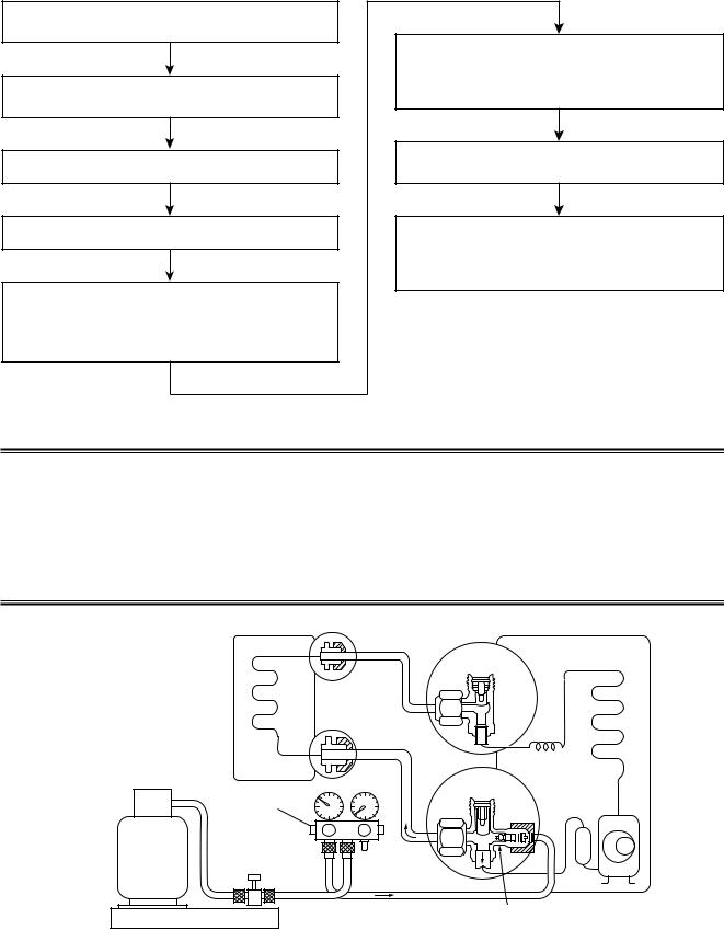
6-4. RechargingofRefrigerant
When it is necessary to recharge refrigerant, charge the specified amount of new refrigerant according to the following steps.
Recover the refrigerant, and check no refrigerant remains in the equipment.
Connect the charge hose to packed valve service port at the outdoor unit’s gas side.
Connect the charge hose to the vacuum pump adapter.
Open fully both packed valves at liquid and gas sides.
Place the handle of the gauge manifold Low in the fully opened position, and turn on the vacuum pump’s power switch.
Then, evacuating the refrigerant in the cycle.
When the compound gauge’s pointer has indicated –0.1 Mpa (–76 cmHg), place the handle Low in the fully closed position, and turn off the vacuum pump’s power switch.
Keep the status as it is for 1 to 2 minutes, and ensure that the compound gauge’s pointer does not return.
Set the refrigerant cylinder to the electronic balance, connect the connecting hose to the cylinder and the connecting port of the electronic balance, and charge liquid refrigerant.
(For refrigerant charging, see the figure below.)
 CAUTION
1.Never charge refrigerant exceeding the specified amount.
2.If the specified amount of refrigerant cannot be charged, charge refrigerant bit by bit in COOL mode.
3.Do not carry out additional charging.
When additional charging is carried out if refrigerant leaks, the refrigerant composition changes in the refrigeration cycle, that is characteristics of the air conditioner changes, refrigerant exceeding the specified amount is charged, and working pressure in the refrigeration cycle becomes abnormally high pressure, and may cause a rupture or personal injury.
(INDOOR unit) |
(Liquid side) |
(OUTDOOR unit) |
Opened
(Gas side)
Refrigerant cylinder (With siphon pipe)
Check valve
Closed
Open/Close valve for charging
Service port
Electronic balance for refrigerant charging
Fig. 6-4-1 Configuration of refrigerant charging
– 23 –
FILE NO. SVM-12004
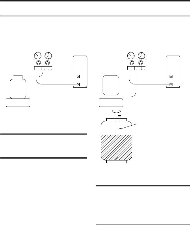
1.Be sure to make setting so that liquid can be charged.
2.When using a cylinder equipped with a siphon, liquid can be charged without turning it upside down.
It is necessary for charging refrigerant under condition of liquid because R410A is mixed type of refrigerant.
Accordingly, when charging refrigerant from the refrigerant cylinder to the equipment, charge it turning the cylinder upside down if cylinder is not equipped with siphon.
[ Cylinder with siphon ] |
[ Cylinder without siphon ] |
Gauge manifold |
Gauge manifold |
OUTDOOR unit |
OUTDOOR unit |
Refrigerant
cylinder
Electronic
balance
cylinder Refrigerant
Electronic
balance
Siphon
R410A refrigerant is HFC mixed refrigerant.
Therefore, if it is charged with gas, the composition of the charged refrigerant changes and the characteristics of the equipment varies.
Fig. 6-4-2
6-5. Brazing of Pipes
6-5-1. Materials for Brazing
1.Silver brazing filler
Silver brazing filler is an alloy mainly composed of silver and copper.
It is used to join iron, copper or copper alloy, and is relatively expensive though it excels in solderability.
2.Phosphor bronze brazing filler
Phosphor bronze brazing filler is generally used to join copper or copper alloy.
3.Low temperature brazing filler
Low temperature brazing filler is generally called solder, and is an alloy of tin and lead.
Since it is weak in adhesive strength, do not use it for refrigerant pipes.
1.Phosphor bronze brazing filler tends to react with sulfur and produce a fragile compound water solution, which may cause a gas leakage.
Therefore, use any other type of brazing filler at a hot spring resort, etc., and coat the surface with a paint.
2.When performing brazing again at time of servicing, use the same type of brazing filler.
6-5-2. Flux
1.Reason why flux is necessary
•By removing the oxide film and any foreign matter on the metal surface, it assists the flow of brazing filler.
•In the brazing process, it prevents the metal surface from being oxidized.
•By reducing the brazing filler’s surface tension, the brazing filler adheres better to the treated metal.
–24 –
2.Characteristicsrequiredforflux
•Activated temperature of flux coincides with the brazing temperature.
•Due to a wide effective temperature range, flux is hard to carbonize.
•It is easy to remove slag after brazing.
•The corrosive action to the treated metal and brazing filler is minimum.
•It excels in coating performance and is harmless to the human body.
As the flux works in a complicated manner as described above, it is necessary to select an adequate type of flux according to the type and shape of treated metal, type of brazing filler and brazing method, etc.
3.Types of flux
•Noncorrosiveflux
Generally, it is a compound of borax and boric acid. It is effective in case where the brazing temperature is higher than 800°C.
•Activated flux
Most of fluxes generally used for silver brazing are this type.
It features an increased oxide film removing capability due to the addition of compounds such as potassium fluoride, potassium chloride and sodium fluoride to the borax-boric acid compound.
4.Piping materials for brazing and used brazing filler/flux
Piping material |
Used brazing filler |
Used flux |
|
|
|
Copper - Copper |
Phosphor copper |
Do not use |
|
|
|
Copper - Iron |
Silver |
Paste flux |
|
|
|
Iron - Iron |
Silver |
Vapor flux |
|
|
|
1.Do not enter flux into the refrigeration cycle.
2.When chlorine contained in the flux remains within the pipe, the lubricating oil deteriorates.
Therefore, use a flux which does not contain chlorine.
3.When adding water to the flux, use water which does not contain chlorine
(e.g. distilled water or ion-exchange water).
4.Remove the flux after brazing.
FILE NO. SVM-12004
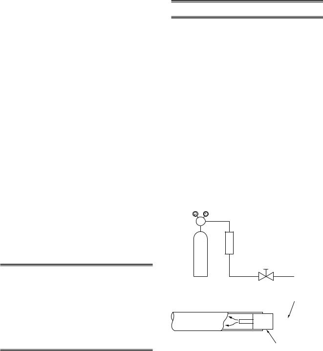
6-5-3. Brazing
As brazing work requires sophisticated techniques, experiences based upon a theoretical knowledge, it must be performed by a person qualified.
In order to prevent the oxide film from occurring in the pipe interior during brazing, it is effective to proceed with brazing while letting dry Nitrogen gas (N2) flow.
Never use gas other than Nitrogen gas.
1.Brazing method to prevent oxidation
1)Attach a reducing valve and a flow-meter to the Nitrogen gas cylinder.
2)Use a copper pipe to direct the piping material, and attach a flow-meter to the cylinder.
3)Apply a seal onto the clearance between the piping material and inserted copper pipe for Nitrogen in order to prevent backflow of the Nitrogen gas.
4)When the Nitrogen gas is flowing, be sure to keep the piping end open.
5)Adjust the flow rate of Nitrogen gas so that it is lower than 0.05 m3/Hr or 0.02 MPa (0.2kgf/cm2) by means of the reducing valve.
6)After performing the steps above, keep the Nitrogen gas flowing until the pipe cools down to a certain extent (temperature at which pipes are touchable with hands).
7)Remove the flux completely after brazing.
M Flow meter
Stop valve
Nitrogen gas cylinder
From Nitrogen cylinder
Pipe 

 Nitrogen gas
Rubber plug
Fig. 6-5-1 Prevention of oxidation during brazing
– 25 –
FILE NO. SVM-12004
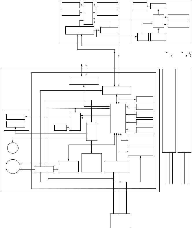
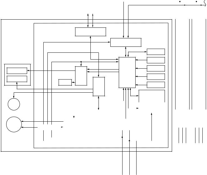
7. INDOOR UNIT CONTROL
7-1. IndoorControllerblockdiagram
7-1-1. Connection of wired remote controller
Wired (Simple) header remote controller (wired) |
Central remote controller |
Display LCD |
|
Function setup |
Display |
LCD driver |
|
|
|
|
LCD |
|
|
|
|
|
|
|
|
Display LED |
CPU |
Key switch |
|
|
|
|
CN2 |
|
|
|
|
|
|
|
|
Function setup |
|
|
|
CN1 |
|
CPU |
|
|
|
DC5V |
|
|
Key switch |
Remote controller |
Power circuit |
DC5V |
|
|
|
communication circuit |
|
|
|||
2 |
|
|
|
||
|
|
Power |
Secondary |
|
|
|
|
Sold separately |
circuit |
battery |
Sold separately |
|
|
|
|
||
|
Central control |
|
|
|
|
|
|
|
|
|
|
|
|
|
|
|
remote controller |
|
|
|
|
|
|
|
|
|
|
|
|
|
|
Indoor unit |
(Sold separately) |
|
|
|
Follower unit |
|
|
|
|
|
|
|
|
||
|
|
|
|
|
#2 A |
|
B #3 A |
|
|
|
|
||||
|
|
|
|
|
|
|
|
|
|
||||||
#1 Header unit |
U3 |
U4 |
A |
|
B |
|
|
B |
|||||||
|
|
|
|
|
|
|
|
|
|
|
|
|
|
|
|
|
Indoor control P.C. board |
|
|
|
|
|
|
|
|
|
|
|
|
(MCC-1510) |
Central control |
|
|
|
|
|
|
|
|
|
|
|
|
|
|
|
|
|
|
|
|
|
||
|
|
communication circuit |
|
|
|
|
|
|
|
|
|
|
|
DC20V |
|
|
Remote controller |
|
|
|
|
|
|
||
|
|
|
|
communication circuit |
|
|
|
|
|
|
||
|
DC12V |
|
|
|
|
|
EEPROM |
|
|
|
|
|
Receiver and |
|
|
|
|
|
|
|
|
|
|
|
|
|
|
|
|
|
|
|
|
|
|
|
|
|
Display P.C. board |
DC5V |
|
|
|
|
|
TA sensor |
|
|
|
|
|
(MCC-5044) |
|
|
|
|
|
|
|
Same as |
||||
|
|
|
|
|
|
|
Same as |
|||||
|
|
|
|
|
|
|
the left |
|
the left |
|
||
Display LED |
|
|
|
|
CPU |
|
TC sensor |
|
|
|
|
|
|
|
|
|
|
|
|
|
|
|
|
||
|
|
Driver |
|
H8/3039 |
|
TCJ sensor |
|
|
|
|
|
|
Receiver unit |
|
|
|
|
|
|
|
|
|
|
||
|
|
|
|
|
|
|
|
|
|
|
|
|
|
|
Buzzer |
|
|
|
|
HA |
|
|
|
|
|
|
|
|
Driver |
|
|
|
|
|
|
|
|
|
|
|
|
|
|
|
|
|
|
|
|
|
|
|
|
|
|
|
|
|
Wireless remote |
|
|
|
|
|
|
|
|
|
|
|
|
signal setting |
|
|
|
|
|
|
|
|
|
|
|
|
(A/B) |
|
|
|
|
|
Louver |
|
|
Outside |
|
|
|
|
|
|
|
|
|
motor |
|
|
|
|
|
Serial send/ |
|
|
|
|
|
|
|
|
|
output |
|
|
|
|
|
|
|
|
|
|
|
|
|
|
|
receive circuit |
|
|
|
|
|
|
|
|
|
|
|
|
|
2 |
3 |
|
2 |
3 |
|
|
|
|
Run/ |
|
|
|
1 |
1 |
||||
|
|
|
Alarm/ |
|
|
|
|
|
|
|
|
|
|
|
|
Ready/ |
|
AC |
|
|
|
|
|
|
|
Indoor |
|
Fan motor |
Thermo. ON/ |
|
|
|
|
|
|
|
|
|
|
synchronous |
|
|
|
|
|
|
|
||||
fan motor |
|
control circuit |
COOL/HEAT/ |
|
|
|
|
|
|
|
||
Power circuit |
FAN |
signal input circuit |
|
|
|
|
|
|
||||
DC280V |
|
|
|
|
|
|
|
|||||
|
|
|
|
|
|
|
|
|
|
|
|
|
|
DC15V |
|
|
|
|
|
|
|
|
|
|
|
|
|
|
|
1 |
2 |
3 |
Outdoor |
Outdoor |
||||
|
|
|
|
|
|
|
unit |
|
unit |
|
||
|
|
|
|
1 |
2 |
3 |
|
|
|
|
|
|
Max. 8 units are connectable. 1
1 When group and twin combination.
Main remote controller shal be connected follower indoor unit.
2 Weekly timer is not connectable to the sub remote controller.
Outdoor unit
– 26 –
FILE NO. SVM-12004
7-1-2. Connection of Wireless Remote Controller
|
Central control |
|
|
|
|
|
|
|
|
|
|
|
|
|
remote controller |
|
|
|
|
|
|
|
|
|
|
|
|
Indoor unit |
(Sold separately) |
|
|
Follower unit |
|
|
|
|
|
|
|
||
|
|
|
|
#2 A |
|
B #3 A |
|
|
|
||||
|
|
|
|
|
|
|
|
||||||
#1 Header unit |
U3 |
U4 |
A |
B |
|
|
B |
||||||
|
|
|
|
|
|
|
|
|
|
|
|
|
|
|
Indoor control P.C. board |
|
|
|
|
(MCC-1510) |
Central control |
|
|
|
|
communication circuit |
|
|
|
DC20V |
|
Remote controller |
|
|
|
|
communication circuit |
|
|
DC12V |
|
EEPROM |
|
Receiver and |
|
|
|
|
|
|
|
|
|
Display P.C. board |
DC5V |
|
TA sensor |
|
(MCC-5044) |
|
Same as |
||
|
|
|
Same as |
|
|
|
|
the left |
the left |
Display LED |
|
|
TC sensor |
|
|
|
CPU |
|
|
|
|
Driver |
H8/3039 |
|
Receiver unit |
|
TCJ sensor |
|
|
|
|
|
|
|
|
Buzzer |
|
HA |
|
|
|
Driver |
|
|
|
|
|
|
|
|
|
|
Wireless remote |
|
|
|
|
signal setting |
|
|
|
|
(A/B) |
|
Louver |
|
|
|
|
|
|
Outside |
|
|
|
|
|
|
|
|
|
|
|
|
|
|
|
|
|
motor |
|
|
|
|
|
|
|
|
|
|
|
Serial send/ |
|
|
|
|
|
|
|
|
|
|
||
|
|
|
|
|
|
|
output |
|
|
|
|
|
|
|
|
|
|
|
|
|
|
|
||
|
|
|
|
|
|
|
|
|
|
|
|
receive circuit |
|
|
|
|
|
|
|
|
|
|
||
|
|
|
|
|
|
|
|
Run/ |
|
|
|
|
|
|
|
1 |
2 |
3 |
|
|
1 |
2 |
3 |
|
|
|
|
|
|
|
|
|
|
|
|
|
|
|
|
||||||||||
|
|
|
|
|
|
|
|
|
|
|
|
|||||||||||||
|
|
|
|
|
|
|
|
Warning/ |
|
|
|
|
|
|
|
|
|
|
|
|
|
|
|
|
|
|
|
|
|
|
|
|
Defrost/ |
|
|
|
|
|
|
|
|
|
|
|
|
|
|
|
|
|
|
|
|
|
|
|
|
|
|
AC |
|
|
|
|
|
|
|
|
|
|
|
|||
Indoor |
|
|
|
|
Fan motor |
|
Thermo. ON/ |
|
|
|
|
|
|
|
|
|
|
|
|
|||||
|
|
|
|
|
|
synchronous |
|
|
|
|
|
|
|
|
|
|
|
|||||||
fan motor |
|
|
|
|
control circuit |
|
COOL/HEAT/ |
|
|
|
|
|
|
|
|
|
|
|
||||||
|
Power circuit |
|
|
|
FAN |
|
signal input circuit |
|
|
|
|
|
|
|
|
|
|
|
||||||
|
DC280V |
|
|
|
|
|
|
|
|
|
|
|
|
|
|
|
|
|
||||||
|
|
|
|
|
|
|
|
|
|
|
|
|
|
|
|
|
|
|
|
|
|
|
|
|
|
|
|
|
|
|
|
|
|
|
|
|
|
|
|
|
|
|
|
|
|
|
|
|
|
|
DC15V |
× |
|
|||
|
|
|
|
|||
|
|
|
|
|
|
|
|
|
|
|
|
|
|
|
L1 L2 S |
|
Outdoor |
Outdoor |
||
|
|
|
|
|
unit |
unit |
|
L1 L2 S |
Max. 8 units are connectable. 1 |
|
1 When group combination, wired remote controller shall be |
|
connected to the follower indoor unit. |
Outdoor unit |
– 27 –
|
|
|
|
|
|
|
|
|
|
|
|
|
|
|
|
|
|
|
|
|
FILE NO. SVM-12004 |
|
7-2. Control Specifications (High Wall Type) |
|
|
|
|
|
|
|
|
|
|||||||||||||
|
|
|
|
|
|
|
|
|
|
|
|
|
|
|
|
|
|
|
|
|
||
No. |
Item |
|
|
|
Outline of specifications |
|
|
|
|
|
|
|
|
Remarks |
||||||||
|
|
|
|
|
|
|
|
|
|
|
|
|
|
|
|
|
|
|||||
1 |
When power |
1) |
Distinction of outdoor unit |
|
|
|
|
|
|
|
|
|
|
|
|
|||||||
|
supply is reset |
|
When the power supply is reset, the outdoors are distin- |
|
|
|||||||||||||||||
|
|
|
|
|
||||||||||||||||||
|
|
|
guished and the control is selected according to the |
|
|
|||||||||||||||||
|
|
|
distinguished result. |
|
|
|
|
|
|
|
|
|
|
|
|
|
|
|
||||
|
|
2) |
Setting of indoor fan speed and existence of air direction |
|
|
|||||||||||||||||
|
|
|
adjustment |
|
|
|
|
|
|
|
|
|
|
|
|
|
|
|
||||
|
|
|
Based on EEPROM data, select setting of the indoor fan |
|
Fan speed (rpm)/ |
|||||||||||||||||
|
|
|
speed and the existence of air direction adjustment. |
|
Air direction adjustment |
|||||||||||||||||
|
|
|
|
|
|
|
|
|
|
|
|
|||||||||||
2 |
Operation |
1) |
Based on the operation mode selecting command from the |
|
|
|||||||||||||||||
|
mode selection |
|
remote controller, the operation mode is selected. |
|
|
|||||||||||||||||
|
|
|
|
|
|
|
|
|
|
|
|
|
|
|
|
|
|
|
|
|
|
|
|
|
|
Remote controller |
|
|
|
|
Control outline |
|
|
|
|||||||||||
|
|
|
|
command |
|
|
|
|
|
|
|
|||||||||||
|
|
|
|
|
|
|
|
|
|
|
|
|
|
|
|
|
|
|
||||
|
|
|
|
|
|
|
|
|
|
|
|
|
|
|
|
|
|
|
||||
|
|
|
|
STOP |
|
Air conditioner stops. |
|
|
|
|
|
|
|
|
|
|||||||
|
|
|
|
|
|
|
|
|
|
|
|
|
|
|
|
|
|
|
||||
|
|
|
|
FAN |
|
Fan operation |
|
|
|
|
|
|
|
|
|
|||||||
|
|
|
|
|
|
|
|
|
|
|
|
|
|
|
|
|
|
|
||||
|
|
|
|
COOL |
|
Cooling operation |
|
|
|
|
|
|
|
|
|
|||||||
|
|
|
|
|
|
|
|
|
|
|
|
|
|
|
|
|
|
|
||||
|
|
|
|
DRY |
|
Dry operation |
|
|
|
|
|
|
|
|
|
|||||||
|
|
|
|
|
|
|
|
|
|
|
|
|
|
|
|
|
|
|
||||
|
|
|
|
HEAT |
|
Heating operation |
|
|
|
|
|
|
|
|
|
|||||||
|
|
|
|
|
|
|
|
|
|
|
|
|
|
Ta: Room temp. |
||||||||
|
|
|
|
AUTO |
|
• COOL/HEAT operation mode is |
|
|
||||||||||||||
|
|
|
|
|
|
|
|
|
|
automatically selected by Ta, Ts |
|
|
Ts: Setup temp. |
|||||||||
|
|
|
|
|
|
|
|
|
|
and To for operation. |
|
|
||||||||||
|
|
|
|
|
|
|
|
|
|
|
|
To: Outside temp. |
||||||||||
|
|
|
|
|
|
|
|
|
• The operation is performed as |
|
|
|||||||||||
|
|
|
|
|
|
|
|
|
|
shown in the following figure |
|
|
|
|||||||||
|
|
|
|
|
|
|
|
|
|
according to Ta value at the first |
|
|
|
|||||||||
|
|
|
|
|
|
|
|
|
|
time only. (In the range of Ts + |
|
|
|
|||||||||
|
|
|
|
|
|
|
|
|
|
α –1 < Ta < Ts + α |
+ 1, Cooling |
|
|
|
||||||||
|
|
|
|
|
|
|
|
|
|
thermo. OFF (Fan)/Setup air |
|
|
|
|||||||||
|
|
|
|
|
|
|
|
|
|
volume operation continues.) |
|
|
|
|||||||||
|
|
|
|
|
|
|
|
|
|
|
|
Cooling |
|
|
|
|
|
|
|
|
|
|
|
|
|
1.0 |
|
|
|
|
|
|
operation |
|
|
|
|
|
|
|
|
|
|||
|
|
|
|
|
|
|
|
|
|
|
|
|
|
|
|
|
||||||
|
|
|
|
|
|
|
|
|
|
|
|
|
|
|
|
|
|
|
|
|||
|
|
|
|
|
|
|
Cooling thermo. OFF (Fan) |
|
|
|
||||||||||||
|
|
|
|
Ta |
|
|
|
|
|
|
|
|||||||||||
|
|
|
|
|
|
|
|
|
|
|
|
|
|
|
|
|
|
|
|
|||
|
|
|
|
˚C Ts + α |
|
|
|
|
• Setup air volume |
|
|
|
|
|
|
|
|
|
||||
|
|
|
|
–1.0 |
|
|
|
|
|
|
|
|
|
|
|
|
|
|
|
|
|
|
|
|
|
|
|
|
|
Heating |
|
|
|
|
|
|
|
|
|
||||||
|
|
|
|
|
|
|
|
|
|
|
|
|
|
|
|
|
|
|
|
|||
|
|
|
|
|
|
|
|
|
|
|
operation |
|
|
|
|
|
|
|
|
|
||
|
|
|
|
• α is corrected according to the outside temperature. |
|
|
|
|||||||||||||||
|
|
|
|
|
|
|
|
|
|
|
|
|
|
|||||||||
|
|
|
|
Outside temp. |
|
|
Correction value (α) |
|
|
|
K = deg |
|||||||||||
|
|
|
|
|
No To |
|
|
|
|
|
|
|
0K |
|
|
|
||||||
|
|
|
|
To ≥ 24°C |
|
|
|
–1K |
|
|
|
|
||||||||||
|
|
|
|
24°C > To ≥ 18°C |
|
|
|
|
0K |
|
|
|
|
|||||||||
|
|
|
|
|
To < 18°C |
|
|
|
+1K |
|
|
|
|
|||||||||
|
|
|
|
|
To error |
|
|
|
|
0K |
|
|
|
|
||||||||
|
|
|
|
|
|
|
|
|
|
|
|
|
|
|
|
|
|
|
|
|
|
|
|
|
|
|
|
|
|
|
|
|
|
|
|
|
|
|
|
|
|
||||
3 |
Room temp. |
1) |
Adjustment range: Remote controller setup temperature °C |
|
|
|||||||||||||||||
|
control |
|
|
|
|
|
|
|
|
|
|
|
|
|
|
|
|
|
|
|
|
|
|
|
|
|
COOL/DRY |
|
HEAT |
|
|
AUTO |
|
|
|
||||||||||
|
|
|
|
|
|
|
|
|
|
|
||||||||||||
|
|
|
Wired type |
|
|
|
|
|
|
|
18°C to 29°C |
|
|
|
|
|
|
|
|
|
||
|
|
|
Wireless type |
|
|
|
|
|
|
|
17°C to 30°C |
|
|
|
|
|
|
|
|
|
||
|
|
|
|
|
|
|
|
|||||||||||||||
|
|
|
When use of remote sensor is set (with DN32), even when sensor value is within |
|||||||||||||||||||
|
|
|
the above range in HEAT or AUTO mode, the thermo. sensor turns OFF when Ta |
|||||||||||||||||||
|
|
|
sensor value exceeds 35°C. |
|
|
|
|
|
|
|
|
|
||||||||||
|
|
|
|
|
|
|
|
|
|
|
|
|
|
|
|
|
|
|
|
|
|
|
– 28 –

|
|
|
|
|
|
|
|
|
|
|
FILE NO. SVM-12004 |
|
|
|
|
|
|
|
|
|
|
|
|
No. |
Item |
|
Outline of specifications |
Remarks |
|||||||
|
|
|
|
|
|
|
|
|
|
|
|
3 |
Room temp. |
2) Using the CODE No. 06, the setup temperature in heating |
Shift of suction |
||||||||
|
control |
|
operation can be corrected. |
temperature in heating |
|||||||
|
(Continued) |
|
|
|
|
|
|
|
|
|
operation |
|
|
|
|
|
|
|
|
|
|
||
|
|
|
|
|
|
|
|
|
|
|
|
|
|
|
|
|
|
|
|
|
|
|
|
Setting at shipment
SET DATA |
3 |
|
|
4 Automatic |
1) |
Based on the difference between Ta and Ts, the operation frequency is instructed to |
|
capacity control |
|
the outdoor unit. |
|
(GA control) |
2) |
Cooling operation |
|
|
|
||
|
|
Every 90 seconds, the room temperature difference between temperature detected by |
|
|
|
Ta and Ts and the varied room temperature value are calculated to obtain the |
|
|
|
correction value of the frequency command and then the present frequency command |
|
|
|
is corrected. |
|
|
|
Ta (n) – Ts (n) |
: Room temp. difference |
|
|
n |
: Counts of detection |
|
|
Ta (n-1) – Ts (n) : Varied room temp. value |
|
|
|
n – 1 |
: Counts of detection of 90 seconds before |
3)Heating operation
Every 1 minute (60 sec.), the room temperature difference between temperature detected by Ta and Ts and the varied room temperature value are calculated to obtain the correction value of the frequency command and then the present frequency command is corrected.
|
|
Ts (n) – Ta (n) |
: Room temp. difference |
|
|||||
|
|
n |
: Counts of detection |
|
|||||
|
|
Ta (n) – Ta (n – 1) : Varied room temp. value |
|
||||||
|
|
n – 1 |
: Counts of detection of 1 minute before |
|
|||||
|
4) |
Dry operation |
|
|
|
|
|
|
|
|
|
The frequency correction control is same as those of the cooling operation. |
|||||||
|
|
However the maximum frequency is limited to approximately “S6”. |
|||||||
|
Note) When LOW is set up, the maximum frequency is limited to approximately “SB”. |
||||||||
|
|
|
|
||||||
5 Automatic |
1) |
The judgment of selecting COOL/HEAT is carried out as |
|
||||||
cooling/heating |
|
shown below. When +1.5°C exceeds against Tsh |
Tsc: Setup temp. in |
||||||
control |
|
10 minutes and after thermo.-OFF, heating operation |
|||||||
|
cooling operation |
||||||||
|
|
(Thermo. OFF) exchanges to cooling operation. |
|||||||
|
|
Tsh: Setup temp. in |
|||||||
|
|
Description in the parentheses shows an example of |
|||||||
|
|
heating operation |
|||||||
|
|
cooling ON/OFF. |
|
|
|
|
|
|
|
|
|
|
|
|
|
|
|
+ temp. correction |
|
|
|
|
|
|
|
|
|
|
|
|
|
|
|
|
|
|
|
|
of room temp. control |
|
|
˚C |
|
Cooling |
|
||||
|
|
+1.5 |
|
|
|
|
|
|
|
|
|
|
|
|
|
(Cooling ON) |
|
||
|
|
Tsc or Tsh |
|
|
|
|
|
||
|
|
|
|
|
|
|
|
|
|
|
|
|
|
|
(Cooling OFF) |
|
|
|
|
|
|
–1.5 |
|
|
|
|
|
||
|
|
|
|
|
|
|
|
|
|
|
|
|
|
|
|
|
|
|
|
|
|
|
|
|
|
Heating |
|
||
|
|
|
|
|
|
|
|||
When –1.5°C lowers against Tsc 10 minutes and after thermo. OFF, cooling operation (Thermo. OFF) exchanges to heating operation.
2)For the automatic capacity control after judgment of cooling/heating, see Item 4.
3)For temperature correction of room temp. control in automatic heating, see Item 3.
– 29 –
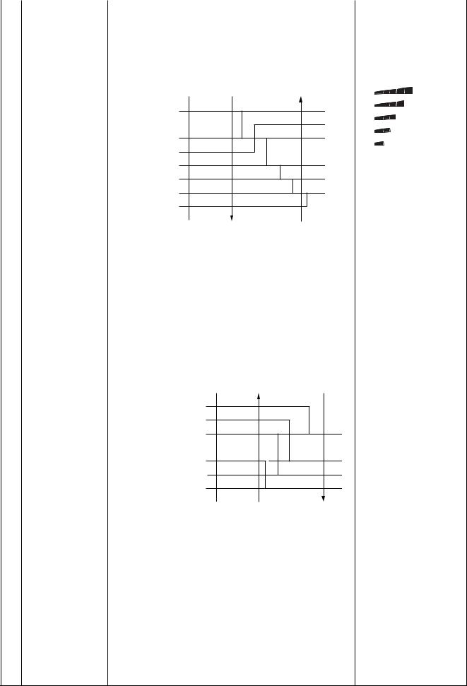
|
|
|
FILE NO. SVM-12004 |
|
|
|
|
No. |
Item |
Outline of specifications |
Remarks |
|
|
|
|
6 |
Fan speed control |
1) Operation with (HH), (H), (L) or [AUTO] mode is carried |
HH > H+ > H > L+ > L > |
|
|
out by the command from the remote controller. |
UL |
2) |
When the fan speed mode [AUTO] is selected, the fan |
|
||
|
speed varies by the difference between Ta and Ts. |
Wireless type allows HH, |
||
|
|
|
|
|
<COOL> |
|
|
H+, H, L+, L and AUTO. |
|
|
|
[HH] |
||
|
|
|
|
|
|
Ta ˚C |
|
A |
[H+] |
|
+3.0 |
|
||
|
|
[H] |
||
|
HH |
B |
||
|
+2.5 |
|||
|
|
|||
|
(HH) |
C |
[L+] |
|
|
+2.0 |
|||
|
|
[L] |
||
|
H+ (HH) |
D |
||
|
|
|||
|
+1.5 |
|
||
|
H (HH) |
|
|
|
|
+1.0 |
|
|
|
|
L+ (H+) |
E |
|
|
|
+0.5 |
|
||
|
L (H) |
|
|
|
|
Tsc |
|
|
|
|
L (H) |
F |
|
|
|
–0.5 |
|
||
|
L (L+) |
G |
|
|
|
|
|
||
•Controlling operation in case when thermo of remote controller works is same as a case when thermo of the body works.
•If the fan speed has been changed once, it is not changed for 3 minutes. However when the air volume is exchanged, the fan speed changes.
•When cooling operation has started, select a downward slope for the fan speed, that is, the high position.
•If the temperature is just on the difference boundary, the fan speed does not change.
•Mode in the parentheses indicates one in automatic cooling operation.
<HEAT>
Ta ˚C |
L (L+) |
|
|
(–0.5) –1.0 |
|
||
L+ (H) |
E |
||
|
|||
(0) Tsh |
|
||
H (H+) |
|
||
(+0.5) +1.0 |
|
||
|
D |
||
|
H+ |
||
|
|
||
(+1.0) +2.0 |
(HH) |
|
|
|
C |
||
(+1.5) +3.0 |
HH |
||
|
|||
(HH) |
B |
||
(+2.0) +4.0 |
|||
|
A |
||
|
|
Value in the parentheses indicates one when thermostat of the remote controller works.
Value without parentheses indicates one when thermostat of the body works.
•If the fan speed has been changed once, it is not changed for 1 minute. However when the fan speed I exchanged, the fan speed changes.
•When heating operation has started, select an upward slope for the fan speed, that is, the high position.
•If the temperature is just on the difference boundary, the fan speed does not change.
• Mode in the parentheses indicates one in automatic |
Tc: Indoor heat |
heating operation. |
exchanger sensor |
• In Tc ≥ 60°C, the fan speed increases by 1 step. |
temperature |
– 30 –
 Loading...