


Toshiba RAV-SM564CT-E, RAV-SM1404BT-TR, RAV-SM804BT-TR, RAV-SM804BT-E, RAV-SM454MUT-TR User Manual
...FILE NO. A10-031
SERVICE MANUAL
SPLIT TYPE
INDOOR UNIT <DIGITAL INVERTER>
Compact 4-way Cassette Type
RAV-SM404MUT-E RAV-SM454MUT-E RAV-SM564MUT-E
Concealed Duct Type
RAV-SM564BT-E RAV-SM804BT-E RAV-SM1104BT-E RAV-SM1404BT-E
Ceiling Type
RAV-SM564CT-E RAV-SM804CT-E RAV-SM1104CT-E RAV-SM1404CT-E
RAV-SM404MUT-TR RAV-SM454MUT-TR RAV-SM564MUT-TR
RAV-SM564BT-TR RAV-SM804BT-TR RAV-SM1104BT-TR RAV-SM1404BT-TR
RAV-SM564CT-TR RAV-SM804CT-TR RAV-SM1104CT-TR RAV-SM1404CT-TR
R410A
PRINTED IN JAPAN, Apr., 2011 ToMo
NOTE
A direct current motor is adopted for indoor fan motor in the Concealed Duct Standard Type air conditioner. Caused from its characteristics, a current limit works on the direct current motor. When replacing the high-performance filter or when opening the service board, be sure to stop the fan. If an above action is executed during the fan operation, the protective control works to stop the unit operation, and the check code “P12” may be issued. However it is not a trouble. When the desired operation has finished, be sure to reset the system to clear “P12” error code using the leak breaker of the indoor unit. Then push the operation stop button of the remote controller to return to the usual operation.
CONTENTS
ORIGINAL INSTRUCTION ................................................................................ |
4 |
||
WARNING INDICATIONS ON THE AIR CONDITIONER UNIT6 |
|
||
PRECAUTION FOR SAFETY ............................................................................ |
7 |
||
NEW REFRIGERANT (R410A) ....................................................................... |
13 |
||
|
1. Safety Caution Concerned to New Refrigerant .................................................... |
13 |
|
|
2. Cautions on Installation/Service............................................................................ |
13 |
|
|
3. Pipe Materials .......................................................................................................... |
13 |
|
1. |
AIR DUCTING WORK............................................................................... |
15 |
|
|
1-1. |
Static Pressure Characteristics ....................................................................... |
15 |
2. |
CONSTRUCTION VIEWS (EXTERNAL VIEWS) ...................................... |
17 |
|
|
2-1. |
Compact 4-way Cassette Type ......................................................................... |
17 |
|
2-2. |
Concealed Duct Type ........................................................................................ |
18 |
|
2-3. |
Ceiling Type ....................................................................................................... |
19 |
3. |
WIRING DIAGRAM ................................................................................... |
20 |
|
|
3-1. |
Indoor Unit......................................................................................................... |
20 |
4. |
SPECIFICATIONS OF ELECTRICAL PARTS .......................................... |
23 |
|
|
4-1. |
Compact 4-way Cassette Type ......................................................................... |
23 |
|
4-2. |
Concealed Duct Type ........................................................................................ |
23 |
|
4-3. |
Ceiling Type ....................................................................................................... |
23 |
5. |
CONTROL BLOCK DIAGRAM ................................................................. |
24 |
|
|
5-1. Indoor Controller Block Diagram..................................................................... |
24 |
|
|
5-2. |
Control Specifications ...................................................................................... |
27 |
|
5-3. |
Indoor Print Circuit Board ................................................................................ |
40 |
– 2 –
6. TROUBLESHOOTING .............................................................................. |
42 |
|
6-1. |
Summary of Troubleshooting........................................................................... |
42 |
6-2. |
Check Code List (Indoor) ................................................................................. |
47 |
6-3. |
Diagnostic Procedure for Each Check Code (Indoor Unit)............................ |
52 |
7. REPLACEMENT OF SERVICE P.C. BOARD ........................................... |
64 |
|
7-1. |
Indoort Unit ....................................................................................................... |
64 |
8. SETUP AT LOCAL SITE AND OTHERS .................................................. |
68 |
|
8-1. |
Indoor Unit......................................................................................................... |
68 |
8-2. |
Setup at Local Site / Others ............................................................................. |
78 |
8-3. |
How to Set up Central Control Address Number ........................................... |
80 |
9. ADDRESS SETUP.................................................................................... |
82 |
|
9-1. |
Address Setup .................................................................................................. |
82 |
9-2. |
Address Setup & Group Control...................................................................... |
83 |
9-3. |
Address Setup (Manual Setting from Remote Controller)............................. |
86 |
9-4. |
Confirmation of Indoor Unit No. Position ....................................................... |
87 |
10. DETACHMENTS ....................................................................................... |
88 |
|
10-1. |
Compact 4-Way Cassette Type ........................................................................ |
88 |
10-2. |
Concealed Duct Type ........................................................................................ |
97 |
10-3. |
Ceiling Type ..................................................................................................... |
100 |
11. EXPLODED VIEWS AND PARTS LIST .................................................. |
104 |
|
11-1. |
Compact 4-way Cassette Type ....................................................................... |
104 |
11-2. |
Concealed Duct Type ...................................................................................... |
108 |
11-3. |
Ceiling Type ..................................................................................................... |
115 |
– 3 –
Original instruction
Please read carefully through these instructions that contain important information which complies with the “Machinery” Directive (Directive 2006/42/EC), and ensure that you understand them.
Generic Denomination: Air Conditioner
Definition of Qualified Installer or Qualified Service Person
The air conditioner must be installed, maintained, repaired and removed by a qualified installer or qualified service person.
When any of these jobs is to be done, ask a qualified installer or qualified service person to do them for you.
A qualified installer or qualified service person is an agent who has the qualifications and knowledge described in the table below.
Agent |
|
Qualifications and knowledge which the agent must have |
|
|
|
Qualified |
• |
The qualified installer is a person who installs, maintains, relocates and removes the air |
installer ( 1) |
|
conditioners made by Toshiba Carrier Corporation. |
|
|
He or she has been trained to install, maintain, relocate and remove the air conditioners made by |
|
|
Toshiba Carrier Corporation or, alternatively, he or she has been instructed in such operations by |
|
|
an individual or individuals who have been trained and is thus thoroughly acquainted with the |
|
|
knowledge related to these operations. |
|
• |
The qualified installer who is allowed to do the electrical work involved in installation, relocation |
|
|
and removal has the qualifications pertaining to this electrical work as stipulated by the local laws |
|
|
and regulations, and he or she is a person who has been trained in matters relating to electrical |
|
|
work on the air conditioners made by Toshiba Carrier Corporation or, alternatively, he or she has |
|
|
been instructed in such matters by an individual or individuals who have been trained and is thus |
|
|
thoroughly acquainted with the knowledge related to this work. |
|
• |
The qualified installer who is allowed to do the refrigerant handling and piping work involved in |
|
|
installation, relocation and removal has the qualifications pertaining to this refrigerant handling |
|
|
and piping work as stipulated by the local laws and regulations, and he or she is a person who |
|
|
has been trained in matters relating to refrigerant handling and piping work on the air conditioners |
|
|
made by Toshiba Carrier Corporation or, alternatively, he or she has been instructed in such |
|
|
matters by an individual or individuals who have been trained and is thus thoroughly acquainted |
|
|
with the knowledge related to this work. |
|
• |
The qualified installer who is allowed to work at heights has been trained in matters relating to |
|
|
working at heights with the air conditioners made by Toshiba Carrier Corporation or, alternatively, |
|
|
he or she has been instructed in such matters by an individual or individuals who have been |
|
|
trained and is thus thoroughly acquainted with the knowledge related to this work. |
|
|
|
Qualified service |
• |
The qualified service person is a person who installs, repairs, maintains, relocates and removes |
person ( 1) |
|
the air conditioners made by Toshiba Carrier Corporation. He or she has been trained to install, |
|
|
repair, maintain, relocate and remove the air conditioners made by Toshiba Carrier Corporation or, |
|
|
alternatively, he or she has been instructed in such operations by an individual or individuals who |
|
|
have been trained and is thus thoroughly acquainted with the knowledge related to these operations. |
|
• |
The qualified service person who is allowed to do the electrical work involved in installation, |
|
|
repair, relocation and removal has the qualifications pertaining to this electrical work as stipulated |
|
|
by the local laws and regulations, and he or she is a person who has been trained in matters |
|
|
relating to electrical work on the air conditioners made by Toshiba Carrier Corporation or, |
|
|
alternatively, he or she has been instructed in such matters by an individual or individuals who |
|
|
have been trained and is thus thoroughly acquainted with the knowledge related to this work. |
|
• |
The qualified service person who is allowed to do the refrigerant handling and piping work |
|
|
involved in installation, repair, relocation and removal has the qualifications pertaining to this |
|
|
refrigerant handling and piping work as stipulated by the local laws and regulations, and he or |
|
|
she is a person who has been trained in matters relating to refrigerant handling and piping |
|
|
work on the air conditioners made by Toshiba Carrier Corporation or, alternatively, he or she |
|
|
has been instructed in such matters by an individual or individuals who have been trained |
|
|
and is thus thoroughly acquainted with the knowledge related to this work. |
|
• |
The qualified service person who is allowed to work at heights has been trained in matters |
|
|
relating to working at heights with the air conditioners made by Toshiba Carrier Corporation or, |
|
|
alternatively, he or she has been instructed in such matters by an individual or individuals who |
|
|
have been trained and is thus thoroughly acquainted with the knowledge related to this work. |
|
|
|
|
|
– 4 – |
Definition of Protective Gear
When the air conditioner is to be transported, installed, maintained, repaired or removed, wear protective gloves and ‘safety’ work clothing.
In addition to such normal protective gear, wear the protective gear described below when undertaking the special work detailed in the table below.
Failure to wear the proper protective gear is dangerous because you will be more susceptible to injury, burns, electric shocks and other injuries.
Work undertaken |
Protective gear worn |
|
|
|
|
All types of work |
Protective gloves |
|
“Safety” working clothing |
||
|
||
|
|
|
|
Gloves to provide protection for electricians and from heat |
|
Electrical-related work |
Insulating shoes |
|
|
Clothing to provide protection from electric shock |
|
|
|
|
Work done at heights (50 cm or more) |
Helmets for use in industry |
|
|
|
|
Transportation of heavy objects |
Shoes with additional protective toe cap |
|
|
|
|
Repair of outdoor unit |
Gloves to provide protection for electricians and from heat |
|
|
|
The important contents concerned to the safety are described on the product itself and on this Service Manual.
Please read this Service Manual after understanding the described items thoroughly in the following contents (Indications/Illustrated marks), and keep them.
[Explanation of indications]
Indication |
Explanation |
|
|
DANGER |
Indicates contents assumed that an imminent danger causing a death or serious injury of |
the repair engineers and the third parties when an incorrect work has been executed. |
Indicates possibilities assumed that a danger causing a death or serious injury of the WARNING repair engineers, the third parties, and the users due to troubles of the product after work
when an incorrect work has been executed.
Indicates contents assumed that an injury or property damage ( ) may be caused on the CAUTION repair engineers, the third parties, and the users due to troubles of the product after work
when an incorrect work has been executed.
Property damage : Enlarged damage concerned to property, furniture, and domestic animal/pet
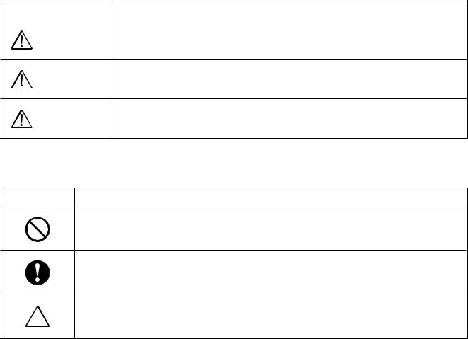
[Explanation of illustrated marks]
Mark |
Explanation |
Indicates prohibited items (Forbidden items to do)
The sentences near an illustrated mark describe the concrete prohibited contents.
Indicates mandatory items (Compulsory items to do)
The sentences near an illustrated mark describe the concrete mandatory contents.
Indicates cautions (Including danger/warning)
The sentences or illustration near or in an illustrated mark describe the concrete cautious contents.
– 5 –
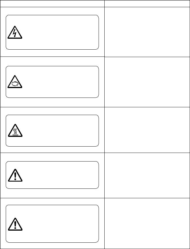
Warning Indications on the Air Conditioner Unit
[Confirmation of warning label on the main unit]
Confirm that labels are indicated on the specified positions
If removing the label during parts replace, stick it as the original.
Warning indication |
Description |
WARNING |
WARNING |
|
|
ELECTRICAL SHOCK HAZARD |
|
ELECTRICAL SHOCK HAZARD |
||
Disconnect all remote electric power supplies |
||
Disconnect all remote electric |
||
before servicing. |
||
power supplies before servicing. |
|
|
|
|
WARNING |
WARNING |
|
|
Moving parts. |
|
Moving parts. |
||
Do not operate unit with grille removed. |
||
Do not operate unit with grille removed. |
||
Stop the unit before the servicing. |
||
Stop the unit before the servicing. |
||
|
||
|
|
CAUTION |
CAUTION |
|
|
|
High temperature parts. |
High temperature parts. |
|
You might get burned when removing |
You might get burned when removing this panel. |
this panel. |
|
|
|
CAUTION |
CAUTION |
|
|
Do not touch the aluminum fins of the unit. |
|
Do not touch the aluminum fins of the unit. |
||
Doing so may result in injury. |
||
Doing so may result in injury. |
||
|
||
|
|
CAUTION |
CAUTION |
|
|
||
BURST HAZARD |
BURST HAZARD |
|
Open the service valves before the |
Open the service valves before the operation, |
|
otherwise there might be the burst. |
||
operation, otherwise there might be the |
||
|
||
burst. |
|
|
|
|
– 6 –
Precaution for Safety
The manufacturer shall not assume any liability for the damage caused by not observing the description of this manual.
 WARNING
|
Before starting to repair the air conditioner, read carefully through the Service Manual, and repair |
|
the air conditioner by following its instructions. |
|
|
|
Only qualified service person ( 1) is allowed to repair the air conditioner. |
|
Repair of the air conditioner by unqualified person may give rise to a fire, electric shocks, injury, |
|
water leaks and/or other problems. |
|
|
|
Only a qualified installer ( 1) or qualified service person ( 1) is allowed to carry out the electrical |
|
work of the air conditioner. |
|
Under no circumstances must this work be done by an unqualified individual since failure to carry |
|
out the work properly may result in electric shocks and/or electrical leaks. |
|
|
|
Wear protective gloves and safety work clothing during installation, servicing and removal. |
|
|
|
When connecting the electrical wires, repairing the electrical parts or undertaking other electrical |
|
jobs, wear gloves to provide protection for electricians and from heat, insulating shoes and |
|
clothing to provide protection from electric shocks. |
|
Failure to wear this protective gear may result in electric shocks. |
|
|
|
Use wiring that meets the specifications in the Installation Manual and the stipulations in the local |
|
regulations and laws. Use of wiring which does not meet the specifications may give rise to |
|
electric shocks, electrical leakage, smoking and/or a fire. |
|
|
|
Only a qualified installer ( 1) or qualified service person ( 1) is allowed to undertake work at heights |
General |
using a stand of 50 cm or more or to remove the intake grille of the indoor unit to undertake work. |
|
|
|
When working at heights, use a ladder which complies with the ISO 14122 standard, and follow |
|
the procedure in the ladder’s instructions. |
|
Also wear a helmet for use in industry as protective gear to undertake the work. |
|
|
|
When working at heights, put a sign in place so that no-one will approach the work location, |
|
before proceeding with the work. |
|
Parts and other objects may fall from above, possibly injuring a person below. |
|
|
|
Do not touch the aluminum fin of the outdoor unit. |
|
You may injure yourself if you do so. If the fin must be touched for some reason, first put on |
|
protective gloves and safety work clothing, and then proceed. |
|
|
|
Do not climb onto or place objects on top of the outdoor unit. |
|
You may fall or the objects may fall off of the outdoor unit and result in injury. |
|
|
|
When transporting the air conditioner, wear shoes with additional protective toe caps. |
|
|
|
When transporting the air conditioner, do not take hold of the bands around the packing carton. |
|
You may injure yourself if the bands should break. |
|
|
|
This air conditioner has passed the pressure test as specified in IEC 60335-2-40 Annex EE. |
|
|
 DENGER
Turn off breaker.
Before carrying out the installation, maintenance, repair or removal work, be sure to set the circuit breaker to the OFF position. Otherwise, electric shocks may result.
Before opening the intake grille of the indoor unit or service panel of the outdoor unit, set the circuit breaker to the OFF position. Failure to set the circuit breaker to the OFF position may result in electric shocks through contact with the interior parts.
Only a qualified installer ( 1) or qualified service person ( 1) is allowed to remove the intake grille of the indoor unit or service panel of the outdoor unit and do the work required.
Before starting to repair the outdoor unit fan or fan guard, be absolutely sure to set the circuit breaker to the OFF position, and place a “Work in progress” sign on the circuit breaker.
When cleaning the filter or other parts of the indoor unit, set the circuit breaker to OFF without fail, and place a “Work in progress” sign near the circuit breaker before proceeding with the work.
– 7 –

|
Even if the circuit breaker has been set to the OFF position before the service panel is removed |
|
and the electrical parts are repaired, you will still risk receiving an electric shock. |
|
For this reason, short-circuit the high-voltage capacitor terminals to discharge the voltage before |
Execute |
proceeding with the repair work. |
discharge |
For details on the short-circuiting procedure, refer to the Service Manual. |
between |
You may receive an electric shock if the voltage stored in the capacitors has not been sufficiently |
terminals. |
discharged. |
|
|
|
Place a “Work in progress” sign near the circuit breaker while the installation, maintenance, repair |
|
or removal work is being carried out. |
Prohibition |
There is a danger of electric shocks if the circuit breaker is set to ON by mistake. |
|
|
|
|
|
If, in the course of carrying out repairs, it becomes absolutely necessary to check out the |
|
electrical parts with the electrical parts box cover of one or more of the indoor units and the |
|
service panel of the outdoor unit removed in order to find out exactly where the trouble lies, wear |
|
insulated heat-resistant gloves, insulated boots and insulated work overalls, and take care to |
Stay on |
avoid touching any live parts. |
protection |
You may receive an electric shock if you fail to heed this warning. Only qualified service person |
|
( 1) is allowed to do this kind of work. |
|
|
 WARNING
|
Before troubleshooting or repair work, check the earth wire is connected to the earth terminals of |
|
|
the main unit, otherwise an electric shock is caused when a leak occurs.If the earth wire is not |
|
|
correctly connected, contact an electric engineer for rework. |
|
|
|
|
|
After completing the repair or relocation work, check that the ground wires are connected properly. |
|
Check earth |
|
|
Be sure to connect earth wire. (Grounding work) Incomplete grounding causes an electric shock. |
||
wires. |
||
Do not connect ground wires to gas pipes, water pipes, and lightning rods or ground wires for |
||
|
||
|
telephone wires. |
|
|
|
|
|
Do not modify the products.Do not also disassemble or modify the parts. |
|
|
It may cause a fire, electric shock or injury. |
|
Prohibition of |
|
|
modification. |
|
|
|
|
|
|
When any of the electrical parts are to be replaced, ensure that the replacement parts satisfy the |
|
|
specifications given in the Service Manual (or use the parts contained on the parts list in the |
|
|
Service Manual). |
|
Use specified |
Use of any parts which do not satisfy the required specifications may give rise to electric shocks, |
|
parts. |
smoking and/or a fire. |
|
|
|
|
|
If, in the course of carrying out repairs, it becomes absolutely necessary to check out the |
|
|
electrical parts with the electrical parts box cover of one or more of the indoor units and the |
|
|
service panel of the outdoor unit removed in order to find out exactly where the trouble lies, place |
|
Do not bring |
"Keep out" signs around the work site before proceeding. |
|
a child close to |
Third-party individuals may enter the work site and receive electric shocks if this warning is not |
|
the equipment. |
heeded. |
|
|
|
|
|
Connect the cut-off lead wires with crimp contact, etc, put the closed end side upward and then |
|
|
apply a water-cut method, otherwise a leak or production of fire is caused at the users’ side. |
|
Insulating |
|
|
measures |
|
|
|
|
|
|
When performing repairs using a gas burner, replace the refrigerant with nitrogen gas because |
|
|
the oil that coats the pipes may otherwise burn. |
|
|
When repairing the refrigerating cycle, take the following measures. |
|
|
1) Be attentive to fire around the cycle. |
|
|
When using a gas stove, etc, be sure to put out fire before work; otherwise the oil mixed with |
|
No fire |
refrigerant gas may catch fire. |
|
2) Do not use a welder in the closed room. |
||
|
||
|
When using it without ventilation, carbon monoxide poisoning may be caused. |
|
|
3) Do not bring inflammables close to the refrigerant cycle, otherwise fire of the welder may catch |
|
|
the inflammables. |
|
|
|
– 8 –

|
The refrigerant used by this air conditioner is the R410A. |
|
Check the used refrigerant name and use tools and materials of the parts which match with it. |
|
For the products which use R410A refrigerant, the refrigerant name is indicated at a position on |
|
the outdoor unit where is easy to see. |
|
To prevent miss-charging, the route of the service port is changed from one of the former R22. |
|
Do not use any refrigerant different from the one specified for complement or replacement. |
|
Otherwise, abnormally high pressure may be generated in the refrigeration cycle, which may |
|
result in a failure or explosion of the product or an injury to your body. |
|
For an air conditioner which uses R410A, never use other refrigerant than R410A. |
|
For an air conditioner which uses other refrigerant (R22, etc.), never use R410A. |
|
If different types of refrigerant are mixed, abnormal high pressure generates in the refrigerating |
|
cycle and an injury due to breakage may be caused. |
|
Do not charge refrigerant additionally. |
|
If charging refrigerant additionally when refrigerant gas leaks, the refrigerant composition in the |
|
refrigerating cycle changes resulted in change of air conditioner characteristics or refrigerant over |
|
the specified standard amount is charged and an abnormal high pressure is applied to the inside |
|
of the refrigerating cycle resulted in cause of breakage or injury. |
Refrigerant |
Therefore if the refrigerant gas leaks, recover the refrigerant in the air conditioner, execute |
|
vacuuming, and then newly recharge the specified amount of liquid refrigerant. |
|
In this time, never charge the refrigerant over the specified amount. |
|
When recharging the refrigerant in the refrigerating cycle, do not mix the refrigerant or air other |
|
than R410A into the specified refrigerant. |
|
If air or others is mixed with the refrigerant, abnormal high pressure generates in the refrigerating |
|
cycle resulted in cause of injury due to breakage. |
|
After installation work, check the refrigerant gas does not leak. |
|
If the refrigerant gas leaks in the room, poisonous gas generates when gas touches to fire such |
|
as fan heater, stove or cocking stove though the refrigerant gas itself is innocuous. |
|
Never recover the refrigerant into the outdoor unit. |
|
When the equipment is moved or repaired, be sure to recover the refrigerant with recovering device. |
|
The refrigerant cannot be recovered in the outdoor unit; otherwise a serious accident such as |
|
breakage or injury is caused. |
|
|
|
After repair work, surely assemble the disassembled parts, and connect and lead the removed |
|
wires as before. |
|
Perform the work so that the cabinet or panel does not catch the inner wires. |
Assembly/ |
If incorrect assembly or incorrect wire connection was done, a disaster such as a leak or fire is |
Cabling |
caused at user’s side. |
|
|
|
After the work has finished, be sure to use an insulation tester set (500V Megger) to check the |
|
resistance is 1MΩ or more between the charge section and the non-charge metal section |
|
(Earth position). |
Insulator |
If the resistance value is low, a disaster such as a leak or electric shock is caused at user’s side. |
check |
|
|
|
|
When the refrigerant gas leaks during work, execute ventilation. |
|
If the refrigerant gas touches to a fire, poisonous gas generates. |
|
A case of leakage of the refrigerant and the closed room full with gas is dangerous because a |
Ventilation |
shortage of oxygen occurs. Be sure to execute ventilation. |
|
|
|
When the refrigerant gas leaks, find up the leaked position and repair it surely. |
|
If the leaked position cannot be found up and the repair work is interrupted, pump-down and |
|
tighten the service valve, otherwise the refrigerant gas may leak into the room. |
|
The poisonous gas generates when gas touches to fire such as fan heater, stove or cocking stove |
|
though the refrigerant gas itself is innocuous. |
|
When installing equipment which includes a large amount of charged refrigerant such as a multi |
|
air conditioner in a sub-room, it is necessary that the density does not the limit even if the |
|
refrigerant leaks. |
|
If the refrigerant leaks and exceeds the limit density, an accident of shortage of oxygen is caused. |
|
|
|
Tighten the flare nut with a torque wrench in the specified manner. |
Compulsion |
Excessive tighten of the flare nut may cause a crack in the flare nut after a long period, which may |
result in refrigerant leakage. |
|
|
|
|
Nitrogen gas must be used for the airtight test. |
|
|
|
The charge hose must be connected in such a way that it is not slack. |
|
|
|
For the installation/moving/reinstallation work, follow to the Installation Manual. |
|
If an incorrect installation is done, a trouble of the refrigerating cycle, water leak, electric shock or |
|
fire is caused. |
|
|
– 9 –
|
Once the repair work has been completed, check for refrigerant leaks, and check the insulation |
|
|
resistance and water drainage. |
|
|
Then perform a trial run to check that the air conditioner is running properly. |
|
|
|
|
|
After repair work has finished, check there is no trouble. If check is not executed, a fire, electric |
|
Check after |
shock or injury may be caused. For a check, turn off the power breaker. |
|
|
||
After repair work (installation of front panel and cabinet) has finished, execute a test run to check |
||
repair |
||
there is no generation of smoke or abnormal sound. |
||
|
||
|
If check is not executed, a fire or an electric shock is caused. Before test run, install the front |
|
|
panel and cabinet. |
Check the following matters before a test run after repairing piping.
• |
Connect the pipes surely and there is no leak of refrigerant. |
• |
The valve is opened. |
Do not |
Running the compressor under condition that the valve closes causes an abnormal high |
operate the |
pressure resulted in damage of the parts of the compressor and etc. and moreover if there is |
unit with the |
leak of refrigerant at connecting section of pipes, the air is suctioned and causes further |
valve closed. |
abnormal high pressure resulted in burst or injury. |
|
|
Only a qualified installer ( 1) or qualified service person ( 1) is allowed to relocate the air |
|
conditioner. It is dangerous for the air conditioner to be relocated by an unqualified individual |
|
since a fire, electric shocks, injury, water leakage, noise and/or vibration may result. |
|
Check the following items after reinstallation.
1)The earth wire is correctly connected.
2)The power cord is not caught in the product.
3) There is no inclination or unsteadiness and the installation is stable.
Check after If check is not executed, a fire, an electric shock or an injury is caused.
reinstallation
When carrying out the pump-down work shut down the compressor before disconnecting the refrigerant pipe.
Disconnecting the refrigerant pipe with the service valve left open and the compressor still operating will cause air, etc. to be sucked in, raising the pressure inside the refrigeration cycle to an abnormally high level, and possibly resulting in reputing, injury, etc.
When the service panel of the outdoor unit is to be opened in order for the compressor or the area around this part to be repaired immediately after the air conditioner has been shut down, set the circuit breaker to the OFF position, and then wait at least 10 minutes before opening the service panel.
If you fail to heed this warning, you will run the risk of burning yourself because the compressor pipes and other parts will be very hot to the touch. In addition, before proceeding with the repair work, wear the kind of insulated heat-resistant gloves designed to protect electricians.
 When the service panel of the outdoor unit is to be opened in order for the fan motor, reactor, Cooling check inverter or the areas around these parts to be repaired immediately after the air conditioner has
been shut down, set the circuit breaker to the OFF position, and then wait at least 10 minutes before opening the service panel.
If you fail to heed this warning, you will run the risk of burning yourself because the fan motor, reactor, inverter heat sink and other parts will be very hot to the touch.
In addition, before proceeding with the repair work, wear the kind of insulated heat-resistant gloves designed to protect electricians.
Only a qualified installer ( 1) or qualified service person ( 1) is allowed to install the air conditioner. If the air conditioner is installed by an unqualified individual, a fire, electric shocks, injury, water leakage, noise and/or vibration may result.
Before starting to install the air conditioner, read carefully through the Installation Manual, and follow its instructions to install the air conditioner.
Do not install the air conditioner in a location that may be subject to a risk of expire to a combustible gas.
If a combustible gas leaks and becomes concentrated around the unit, a fire may occur.
Install the indoor unit at least 2.5 m above the floor level since otherwise the users may injure Installation themselves or receive electric shocks if they poke their fingers or other objects into the indoor unit
while the air conditioner is running.
Install a circuit breaker that meets the specifications in the installation manual and the stipulations in the local regulations and laws.
Install the circuit breaker where it can be easily accessed by the qualified service person ( 1).
Do not place any combustion appliance in a place where it is directly exposed to the wind of air conditioner, otherwise it may cause imperfect combustion.
– 10 –
Explanations given to user
•If you have discovered that the fan grille is damaged, do not approach the outdoor unit but set the circuit breaker to the OFF position, and contact a qualified service person to have the repairs done. Do not set the circuit breaker to the ON position until the repairs are completed.
Relocation
•Only a qualified installer ( 1) or qualified service person ( 1) is allowed to relocate the air conditioner.
It is dangerous for the air conditioner to be relocated by an unqualified individual since a fire, electric shocks, injury, water leakage, noise and/or vibration may result.
•When carrying out the pump-down work shut down the compressor before disconnecting the refrigerant pipe. Disconnecting the refrigerant pipe with the service valve left open and the compressor still operating will cause air, etc. to be sucked in, raising the pressure inside the refrigeration cycle to an abnormally high level, and possibly resulting in reputing, injury, etc.
( 1) Refer to the “Definition of Qualified Installer or Qualified Service Person.”
Declaration of Conformity
Manufacturer: |
Toshiba Carrier Corporation |
|
336 Tadehara, Fuji-shi, Shizuoka-ken 416-8521 JAPAN |
Authorized |
Nick Ball |
Representative/TCF holder: |
Toshiba EMEA Engineering Director |
|
Toshiba Carrier UK Ltd. |
|
Porsham Close, Belliver Industrial Estate, |
|
PLYMOUTH, Devon, PL6 7DB. |
|
United Kingdom |
Hereby declares that the machinery described below:
Generic Denomination: |
Air Conditioner |
Model/type: |
RAV-SM404MUT-E |
|
RAV-SM454MUT-E |
|
RAV-SM564MUT-E |
|
RAV-SM564BT-E |
|
RAV-SM804BT-E |
|
RAV-SM1104BT-E |
|
RAV-SM1404BT-E |
|
RAV-SM564CT-E |
|
RAV-SM804CT-E |
|
RAV-SM1104CT-E |
|
RAV-SM1404CT-E |
RAV-SM404MUT-TR RAV-SM454MUT-TR RAV-SM564MUT-TR
RAV-SM564BT-TR RAV-SM804BT-TR RAV-SM1104BT-TR RAV-SM1404BT-TR
RAV-SM564CT-TR RAV-SM804CT-TR RAV-SM1104CT-TR RAV-SM1404CT-TR
Commercial name: |
Digital Inverter Series / Super Digital Inverter Series Air Conditioner |
Complies with the provisions of the “Machinery” Directive (Directive 2006/42/EC) and the regulations transposing into national law.
Complies with the provisions of the following harmonized standard:
EN 378-2: 2008 / A1: 2009
Note: This declaration becomes invalid if technical or operational modifications are introduced without the manufacturer’s consent.
– 11 –
Specifications
Model |
Sound power level (dBA) |
Weight (kg) |
||
Cooling |
Heating |
Main unit (Ceiling panel) |
||
|
||||
|
|
|
|
|
RAV-SM404MUT-E |
|
|
16 (3) |
|
|
|
|
|
|
RAV-SM454MUT-E |
|
|
16 (3) |
|
|
|
|
|
|
RAV-SM564MUT-E |
|
|
16 (3) |
|
|
|
|
|
|
RAV-SM404MUT-TR |
|
|
16 (3) |
|
|
|
|
|
|
RAV-SM454MUT-TR |
|
|
16 (3) |
|
|
|
|
|
|
RAV-SM564MUT-TR |
|
|
16 (3) |
|
|
|
|
|
|
RAV-SM564BT-E |
|
|
30 |
|
|
|
|
|
|
RAV-SM804BT-E |
|
|
39 |
|
|
|
|
|
|
RAV-SM1104BT-E |
|
|
54 |
|
|
|
|
|
|
RAV-SM1404BT-E |
|
|
54 |
|
|
|
|
|
|
RAV-SM564BT-TR |
|
|
30 |
|
|
|
|
|
|
RAV-SM804BT-TR |
|
|
39 |
|
|
|
|
|
|
RAV-SM1104BT-TR |
|
|
54 |
|
|
|
|
|
|
RAV-SM1404BT-TR |
|
|
54 |
|
|
|
|
|
|
RAV-SM564CT-E |
|
|
21 |
|
|
|
|
|
|
RAV-SM804CT-E |
|
|
25 |
|
|
|
|
|
|
RAV-SM1104CT-E |
|
|
33 |
|
|
|
|
|
|
RAV-SM1404CT-E |
|
|
33 |
|
|
|
|
|
|
RAV-SM564CT-TR |
|
|
21 |
|
|
|
|
|
|
RAV-SM804CT-TR |
|
|
25 |
|
|
|
|
|
|
RAV-SM1104CT-TR |
|
|
33 |
|
|
|
|
|
|
RAV-SM1404CT-TR |
|
|
33 |
|
|
|
|
|
|
: Under 70 dBA
• Other specifications than abovementioned models are equal to current models (2 series).
– 12 –

New Refrigerant (R410A)
This air conditioner adopts a new HFC type refrigerant (R410A) which does not deplete the ozone layer.
1. Safety Caution Concerned to New Refrigerant
The pressure of R410A is high 1.6 times of that of the former refrigerant (R22). Accompanied with change of refrigerant, the refrigerating oil has been also changed.
Therefore, be sure that water, dust, the former refrigerant or the former refrigerating oil is not mixed into the refrigerating cycle of the air conditioner with new refrigerant during installation work or service work.
If an incorrect work or incorrect service is performed, there is a possibility to cause a serious accident. Use the tools and materials exclusive to R410A to purpose a safe work.
2.Cautions on Installation/Service
1)Do not mix the other refrigerant or refrigerating oil.
For the tools exclusive to R410A, shapes of all the joints including the service port differ from those of the former refrigerant in order to prevent mixture of them.
2)As the use pressure of the new refrigerant is high, use material thickness of the pipe and tools which are specified for R410A.
3)In the installation time, use clean pipe materials and work with great attention so that water and others do not mix in because pipes are affected by impurities such as water, oxide scales, oil, etc.
Use the clean pipes.
Be sure to brazing with flowing nitrogen gas. (Never use gas other than nitrogen gas.)
4)For the earth protection, use a vacuum pump for air purge.
5)R410A refrigerant is azeotropic mixture type refrigerant.
Therefore use liquid type to charge the refrigerant. (If using gas for charging, composition of the refrigerant changes and then characteristics of the air conditioner change.)
3.Pipe Materials
For the refrigerant pipes, copper pipe and joints are mainly used.
It is necessary to select the most appropriate pipes to conform to the standard.
Use clean material in which impurities adhere inside of pipe or joint to a minimum.
1) Copper pipe
<Piping>
The pipe thickness, flare finishing size, flare nut and others differ according to a refrigerant type.
When using a long copper pipe for R410A, it is recommended to select “Copper or copper-base pipe without seam” and one with bonded oil amount 40mg/10m or less.
Also do not use crushed, deformed, discolored (especially inside) pipes. (Impurities cause clogging of expansion valves and capillary tubes.)
<Flare nut>
Use the flare nuts which are attached to the air conditioner unit.
2)Joint
The flare joint and socket joint are used for joints of the copper pipe. The joints are rarely used for installation of the air conditioner. However clear impurities when using them.
– 13 –
4.Tools
1.Required Tools for R410A
Mixing of different types of oil may cause a trouble such as generation of sludge, clogging of capillary, etc. Accordingly, the tools to be used are classified into the following three types.
1)Tools exclusive for R410A (Those which cannot be used for conventional refrigerant (R22))
2)Tools exclusive for R410A, but can be also used for conventional refrigerant (R22)
3)Tools commonly used for R410A and for conventional refrigerant (R22)
The table below shows the tools exclusive for R410A and their interchangeability.
Tools exclusive for R410A (The following tools for R410A are required.)
Tools whose specifications are changed for R410A and their interchangeability
|
|
|
|
R410A |
Conventional air |
|
|
|
|
air conditioner installation |
conditioner installation |
||
No. |
Used tool |
Usage |
|
|
|
|
Existence of |
Whether conventional |
Whether |
||||
|
|
|
||||
|
|
|
new equipment |
conventional equipment |
||
|
|
|
equipment can be used |
|||
|
|
|
for R410A |
can be used |
||
|
|
|
|
|||
|
|
|
|
|
|
|
Q |
Flare tool |
Pipe flaring |
Yes |
(Note) |
Yes |
|
|
|
|
|
|
|
|
|
Copper pipe gauge |
Flaring by |
|
|
|
|
R |
for adjusting |
Yes |
(Note) |
(Note) |
||
conventional flare tool |
||||||
|
projection margin |
|
|
|
||
|
|
|
|
|
||
|
|
|
|
|
|
|
S |
Torque wrench |
Tightening of flare nut |
Yes |
No |
No |
|
|
|
|
|
|
|
|
T |
Gauge manifold |
Evacuating, refrigerant |
|
|
|
|
|
|
Yes |
No |
No |
||
U |
Charge hose |
charge, run check, etc. |
||||
|
|
|
||||
|
|
|
|
|||
|
|
|
|
|
|
|
V |
Vacuum pump adapter |
Vacuum evacuating |
Yes |
No |
Yes |
|
|
|
|
|
|
|
|
W |
Electronic balance for |
Refrigerant charge |
Yes |
Yes |
Yes |
|
|
refrigerant charging |
|
|
|
|
|
|
|
|
|
|
|
|
X |
Refrigerant cylinder |
Refrigerant charge |
Yes |
No |
No |
|
|
|
|
|
|
|
|
Y |
Leakage detector |
Gas leakage check |
Yes |
No |
Yes |
|
|
|
|
|
|
|
|
(Note) When flaring is carried out for R410A using the conventional flare tools, adjustment of projection margin is necessary. For this adjustment, a copper pipe gauge, etc. are necessary.
General tools (Conventional tools can be used.)
In addition to the above exclusive tools, the following equipments which serve also for R22 are necessary as the general tools.
1)Vacuum pump. Use vacuum pump by attaching vacuum pump adapter.
2)Torque wrench
3)Pipe cutter
4)Reamer
5)Pipe bender
6)Level vial
7)Screwdriver (+, –)
8)Spanner or Monkey wrench
9)Hole core drill
10)Hexagon wrench (Opposite side 4mm)
11)Tape measure
12)Metal saw
Also prepare the following equipments for other installation method and run check.
1) |
Clamp meter |
3) |
Insulation resistance tester (Megger) |
2) |
Thermometer |
4) |
Electroscope |
– 14 –
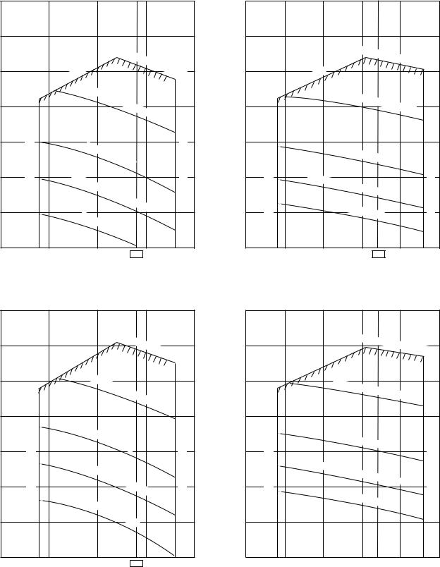
1. AIR DUCTING WORK
1-1. Static Pressure Characteristics
Concealed Duct type
RAV-SN564BT , RAV-SN804BT , RAV-SN1104BT , RAV-SN1404BT
Fig. 1 SM56 type (Round duct) |
Fig. 3 SM80 type (Round duct) |
Standard air volume 780m³/h |
Standard air volume 1140m³/h |
|
140 |
|
|
|
|
|
|
|
|
|
|
|
|
|
|
140 |
|
|
|
|
|
|
|
|
|
|
|
|
|
120 |
|
|
|
|
|
|
|
|
|
|
|
|
|
|
120 |
|
|
|
|
|
|
|
|
|
|
|
|
|
|
|
|
|
|
|
High |
static |
pressure |
|
|
|
|
|
|
|
|
High |
static |
pressure |
|
|||||||
|
|
|
|
|
|
|
|
|
|
|
|
|
|
|
|
|
|
|
||||||||||
|
|
|
|
|
|
|
|
|
|
|
|
|
|
|
|
|
|
|
|
|
|
|||||||
|
|
|
|
|
|
|
|
|
|
|
|
|
|
|
|
|
|
|
|
|
|
|
||||||
|
100 |
|
|
|
|
|
|
|
|
2H |
|
|
100 |
|
|
|
|
|
|
|
|
|
|
2H |
tap |
|||
|
|
limit |
|
|
|
|
tap |
|
|
|
|
|
|
|
|
|
|
|
|
|||||||||
|
|
|
|
|
|
|
|
|
|
|
|
|
|
|
|
|
|
|
||||||||||
|
Usable |
|
|
|
|
|
|
|
|
|
|
limit |
|
|
|
|
|
|
|
|
||||||||
|
|
|
|
|
|
|
|
|
|
|
|
|
|
|
|
Usable |
|
|
|
|
|
|
|
|
||||
|
|
|
|
High |
|
|
|
|
|
|
|
|
|
|
|
|
|
High |
|
|
|
|
|
|
|
|||
|
|
|
|
|
|
|
|
|
|
|
|
|
|
|
|
|
|
|
|
|
|
|
|
|
||||
|
|
|
|
|
|
|
|
|
|
|
|
|
|
|
|
|
|
|
|
|
|
|
|
|
|
|||
(Pa) |
|
|
|
|
|
static |
pressure |
|
|
|
|
(Pa) |
|
|
|
|
|
static |
pressure |
1H |
|
|
||||||
80 |
|
|
|
|
|
|
|
|
80 |
|
|
|
|
|
tap |
|
||||||||||||
|
|
|
|
|
|
|
1H |
|
|
|
|
|
|
|
|
|
||||||||||||
Static pressure |
|
|
|
|
|
|
|
|
tap |
|
Static pressure |
|
|
|
|
|
|
|
|
|
|
|
|
|||||
|
|
|
|
|
|
|
|
|
|
|
|
|
|
|
|
|
|
|
|
|
|
|||||||
|
|
|
|
|
|
|
|
|
|
Air volume limit (Max.) |
|
|
|
|
|
|
|
|
|
|
|
|
|
|||||
|
|
|
|
|
|
|
|
|
|
|
|
|
|
|
|
|
|
|
|
|
|
|
|
|||||
60 |
|
|
|
Standard |
|
|
|
|
|
|
60 |
|
|
|
Standard H |
|
|
|
|
|
|
|||||||
|
|
|
|
H |
|
|
|
|
|
volume limit (Min.) |
|
|
tap |
|
|
|
volumelimit (Max.) |
|||||||||||
|
|
|
|
|
|
|
|
|
|
|
|
|
|
|
|
|
||||||||||||
|
|
|
|
|
|
|
|
tap |
|
|
|
|
|
|
|
|
|
|
|
|
|
|
|
|||||
40 |
Lo |
w |
static |
|
|
|
|
|
|
|
40 |
Low |
static |
|
|
|
|
|
|
|||||||||
|
|
|
|
|
|
|
|
|
|
|
|
|
|
|
||||||||||||||
|
|
|
|
|
|
|
|
|
|
|
|
|
|
|
|
|
|
|
||||||||||
|
|
|
|
|
|
|
|
|
|
|
|
|
|
|
|
|
|
|
|
|||||||||
|
|
|
|
|
|
|
|
|
|
|
|
|
|
|
p |
|
|
|
|
|
|
|||||||
|
|
|
|
pressure |
|
|
|
|
|
|
|
|
ressure |
H tap |
|
|
||||||||||||
|
|
|
|
|
|
|
|
|
|
|
|
|
|
|
|
|
|
|
||||||||||
|
|
|
|
|
|
|
|
|
|
|
|
|
|
|
|
|
|
|
|
|
||||||||
|
|
|
|
|
|
|
|
H |
|
|
|
|
|
|
|
|
|
|
|
|
|
|
||||||
20 |
|
|
|
|
|
|
|
|
tap |
|
|
20 |
|
|
|
Standard L |
|
|
|
|
||||||||
(Min.)limitvolumeAir |
|
|
Standard |
|
|
|
|
|
|
|
|
|
|
|
|
|
tap |
|
|
|||||||||
|
|
|
|
|
|
|
|
|
|
|
|
|
Air |
|
|
|
|
|
|
|
|
Air |
||||||
|
|
|
|
|
|
|
|
|
|
|
|
|
|
|
|
|
|
|
|
|
|
|
||||||
|
|
|
|
|
|
|
|
|
|
|
|
|
|
|
|
|
|
|
|
|
|
|
|
|
||||
|
|
|
|
|
|
|
L |
tap |
|
|
|
|
|
|
|
|
|
|
|
|
|
|
|
|
|
|
|
|
|
|
|
|
|
|
|
|
|
|
|
|
|
|
|
|
|
|
|
|
|
|
|
|
|
|
|
||
|
0 |
|
|
|
|
|
|
|
|
|
|
|
|
|
|
0 |
|
|
|
|
|
|
|
|
|
|
|
|
|
500 |
|
|
|
700 |
|
|
780 |
|
|
|
900 |
|
800 |
|
|
1000 |
|
|
|
1140 |
1200 |
1300 |
|||||
Air volume m³/h |
Air volume m³/h |
Fig. 2 SM56 type (Square duct) |
Fig. 4 SM80 type (Square duct) |
Standard air volume 780m³/h |
Standard air volume 1140m³/h |
|
140 |
|
|
|
|
|
|
|
|
|
|
|
|
140 |
|
|
|
|
|
|
High |
static |
pressure |
|
|
|
|
|
|||
|
120 |
|
|
|
|
|
|
|
|
120 |
|
||||
|
|
|
|
|
|
|
|
|
|
|
|||||
|
|
|
|
|
|
|
|
|
|
|
|
|
|
||
|
|
|
limit |
|
|
|
|
|
|
|
2H |
tap |
|
|
|
|
108 |
Usable |
|
|
|
|
|
|
|
|
|
|
|
||
|
|
|
|
|
|
|
|
|
|
|
|
|
|
||
|
|
|
|
|
|
|
|
|
|
|
|
|
|
|
|
|
100 |
|
High |
static |
|
|
|
|
|
|
|
100 |
Usable |
||
|
|
|
|
|
|
|
|
|
|
||||||
|
|
|
|
|
press |
ure |
|
|
|
|
|
|
|
||
|
|
|
|
|
|
|
1H |
|
|
|
|
|
|
||
|
|
|
|
|
|
|
|
tap |
|
|
|
|
|||
(Pa) |
|
|
|
|
|
|
|
|
|
(Pa) |
|
|
|||
80 |
|
|
|
|
|
|
|
|
|
80 |
|
||||
|
|
|
|
|
|
|
|
|
|
(Max.)limitvolumeAir |
(Min.)limitvolumeAir |
||||
pressureStatic |
(Min.)limitvolumeAir |
|
Standard |
|
|
|
|
|
pressureStatic |
|
|||||
|
|
|
|
|
|
H |
|
|
|
|
|
|
|
|
|
|
60 |
|
|
|
|
|
tap |
|
|
|
|
|
|
60 |
|
|
|
|
|
|
|
|
|
|
|
|
|
|
|
||
|
|
|
Low |
static |
|
|
|
|
|
|
|
|
|
|
|
|
|
|
|
pressure |
|
|
|
|
|
|
|
|
|||
|
40 |
|
|
|
|
H |
|
|
|
|
|
40 |
|
||
|
|
|
|
|
|
|
|
|
|
|
|
|
|
|
|
|
|
|
|
|
|
|
|
tap |
|
|
|
|
|
|
|
|
|
|
|
Standard |
|
|
|
|
|
|
|
|
|||
|
|
|
|
|
|
|
L |
|
|
|
|
|
|
|
|
|
20 |
|
|
|
|
|
tap |
|
|
|
|
|
20 |
|
|
|
|
|
|
|
|
|
|
|
|
|
|
|
|
||
|
0 |
|
|
|
|
|
|
|
|
|
|
|
|
0 |
|
|
500 |
|
|
700 |
|
780 |
|
|
|
|
900 |
800 |
|
||
High |
|
|
static |
pressure |
|
|
|
2H |
limit |
|
|
High |
|
|
static |
|
|
pressure |
|
|
|
1H |
tap |
|
|
|
Standard |
|
|
H tap |
|
|
Low |
|
|
static |
|
|
pressure |
|
|
H tap |
|
|
Standard |
|
|
L tap |
|
|
1000 |
1140 |
1200 |
tap
Air volume limit (Max.)
1300
Air volume m³/h |
Air volume m³/h |
– 15 –
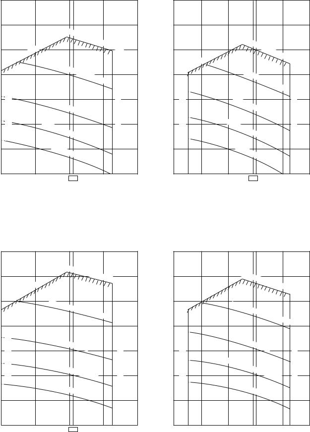
Fig. 5 SM110 type (Round duct) |
Fig. 7 SM140 type (Round duct) |
Standard air volume 1620m³/h |
Standard air volume 1980m³/h |
|
140 |
|
|
|
|
|
|
|
|
|
|
|
|
|
|
|
|
|
140 |
|
|
|
|
|
|
|
|
|
|
|
|
|
|
|
|
|
|
|
120 |
|
|
|
|
|
|
|
|
|
|
|
|
|
|
|
|
|
120 |
|
|
|
|
|
|
|
|
|
|
|
|
|
|
|
|
|
|
|
|
|
|
|
|
|
High |
static |
pressure |
|
|
|
|
|
|
|
High |
|
|
|
|
|
|
|
|
|
|
|
|
||||||||
|
|
|
|
|
|
|
|
|
|
|
|
|
|
|
|
static |
|
|
|
|
|
|
|
||||||||||||||
|
|
|
|
|
|
|
|
|
|
|
|
2H |
|
|
|
|
|
|
|
|
|
|
|
|
|
||||||||||||
|
100 |
|
limit |
|
|
|
|
|
|
|
|
tap |
|
100 |
|
|
|
|
|
|
pressure |
|
|
||||||||||||||
|
|
|
|
|
|
|
|
|
|
|
|
|
|
|
|
|
|
|
|
|
|
|
|||||||||||||||
|
Usable |
|
|
|
|
|
|
|
|
|
|
|
|
|
|
|
|
|
|
|
|
|
|
|
|
|
2H |
|
|||||||||
|
|
|
|
|
|
|
|
|
|
|
|
|
|
|
|
|
|
|
|
|
|
|
|
|
|
|
|
|
|
|
|
||||||
|
|
|
|
|
|
|
|
|
|
|
|
|
|
|
|
|
|
|
Usable |
limit |
|
|
|
|
|
|
|
|
|
|
|
|
|
|
tap |
||
|
|
|
|
High |
static |
|
|
|
|
|
|
|
|
|
|
|
|
High |
|
|
|
|
|
|
|
|
|
|
|
|
|
||||||
(Pa) |
|
|
|
|
|
|
|
|
|
|
|
|
|
(Pa) |
|
static |
|
|
|
|
|
|
|
|
|
|
|
||||||||||
|
|
|
pressure |
|
|
|
|
|
|
|
|
|
|
|
|
|
|
|
|
|
|||||||||||||||||
80 |
|
|
|
|
|
|
|
|
|
|
|
|
|
|
|
|
|
|
|
|
|
||||||||||||||||
|
|
|
|
|
|
|
|
80 |
|
|
|
|
pressure |
|
|
|
|
||||||||||||||||||||
|
|
|
|
|
|
1H |
|
|
|
|
|
|
|
|
|
|
|
||||||||||||||||||||
pressureStatic |
|
|
|
|
|
|
|
tap |
|
pressureStatic |
|
|
|
|
|
|
|
|
|
|
|
|
|||||||||||||||
|
|
|
|
|
|
|
|
|
|
|
|
|
|
|
|
|
|
|
|
|
|
1H |
|
|
|
||||||||||||
|
(Min.)limitvolumeAir |
|
|
|
|
pressure H |
|
|
|
|
(Max.)limitvolumeAir |
(Min.)limitvolumeAir |
|
|
|
|
|
|
|
|
|
|
|
|
H |
|
|
tap |
(Max.)limitvolumeAir |
||||||||
|
|
|
|
|
|
|
|
|
|
|
|
|
|
|
|
|
|
|
|
|
|
|
|
|
|
|
|
|
|
|
|
|
|
|
|
||
|
|
|
|
|
|
|
|
|
|
|
|
|
|
|
|
|
|
|
|
|
|
|
|
|
|
|
|
|
|
|
|
|
|
|
|
|
|
|
60 |
|
|
|
Standard |
|
|
|
|
|
|
|
|
|
60 |
|
|
|
Standard |
|
|
|
|
|
|
|
|
|
|
||||||||
|
|
|
|
|
H |
|
|
|
|
|
|
|
|
|
|
|
|
H |
tap |
|
|
|
|
|
|||||||||||||
|
|
|
|
|
tap |
|
|
|
|
|
|
|
|
|
|
|
|
|
|
|
|
|
|
|
|
||||||||||||
|
|
|
|
|
|
|
|
|
|
|
|
|
|
|
|
|
|
|
|
|
|
|
|
|
|
|
|
|
|
|
|
||||||
|
|
|
|
|
|
|
|
|
|
|
|
|
|
|
|
|
|
|
Low |
|
|
|
|
|
|
|
|
|
|
|
|
|
|
|
|
||
|
40 |
|
|
Low |
static |
|
|
|
|
|
|
|
|
|
|
|
|
40 |
|
static |
|
|
|
|
|
|
|
|
|
|
|
|
|
||||
|
|
|
|
|
|
|
|
|
|
|
|
|
|
|
|
|
|
|
pressure |
|
|
|
|
|
|
||||||||||||
|
|
|
|
|
|
|
|
|
|
|
|
|
|
|
|
|
|
|
|
|
|
|
|
|
|
||||||||||||
|
|
|
|
|
|
|
|
|
|
|
|
|
|
|
|
|
|
|
|
|
|
|
|
|
|
|
|
|
|||||||||
|
|
|
|
|
|
|
|
|
|
|
|
|
tap |
|
|
|
|
|
|
|
|
|
|
|
tap |
|
|
|
|||||||||
|
|
|
|
|
Standard |
|
|
|
|
|
|
|
|
|
|
|
|
Standard |
|
|
|
|
|
|
|
|
|
||||||||||
|
20 |
|
|
|
|
|
|
|
|
|
|
|
|
20 |
|
|
|
|
|
|
|
|
|
|
|
|
|
||||||||||
|
|
|
|
|
|
|
|
|
|
|
|
|
|
|
|
|
|
|
|
|
|
|
|
|
|
|
|
||||||||||
|
|
|
|
|
|
|
|
|
|
|
|
|
|
|
|
|
|
|
|
|
|
|
|
|
|
|
|
|
|
|
|
|
|
|
|
||
|
|
|
|
|
|
|
|
L |
tap |
|
|
|
|
|
|
|
|
|
|
|
|
|
|
|
L |
tap |
|
|
|
|
|
|
|||||
|
|
|
|
|
|
|
|
|
|
|
|
|
|
|
|
|
|
|
|
|
|
|
|
|
|
|
|
|
|
|
|
|
|||||
|
0 |
|
|
|
|
|
1620 |
|
|
|
|
|
|
|
|
|
0 |
|
|
|
|
|
|
1980 |
|
|
|
|
|
|
|
|
|||||
|
1200 |
|
|
|
|
|
|
|
|
|
|
|
|
2000 |
|
1200 |
|
1800 |
|
|
|
|
|
|
|
|
2200 |
2400 |
|||||||||
Air volume m³/h |
Air volume m³/h |
Fig. 6 SM110 type (Square duct)
Fig. 8 SM140 type (Square duct)
Standard air volume 1620m³/h |
Standard air volume 1980m³/h |
|
140 |
|
|
|
|
|
|
|
|
|
|
|
|
140 |
|
|
|
|
|
High |
static |
pressure |
|
|
|
|
|
|
|
||
|
120 |
|
|
|
2H |
|
|
|
120 |
|
|||||
|
|
|
|
|
tap |
|
|
|
|||||||
|
|
|
|
|
|
|
|
|
|
|
|
|
|||
|
|
|
|
limit |
|
|
|
|
|
|
|
|
|
|
|
|
|
|
Usable |
|
|
|
|
|
|
|
|
|
|
|
|
|
|
|
|
|
|
|
|
|
|
|
|
|
|
Usable |
|
|
100 |
|
|
High |
|
|
|
|
|
|
|
|
|
100 |
|
|
|
|
|
|
|
|
|
|
|
|
|
|
|||
|
|
|
|
|
|
|
|
|
|
|
|
|
|
|
|
|
|
|
|
static |
|
|
|
|
|
|
|
|
|
|
|
|
|
|
|
|
pressure |
|
|
|
|
|
|
|
|||
|
|
|
|
|
|
|
|
1H |
tap |
|
|
|
|
||
(Pa) |
|
|
|
|
|
|
|
|
|
|
(Pa) |
|
|
||
80 |
limitvolumeAir(Min.) |
|
|
|
|
|
|
|
|
|
limitvolumeAir(Max.) |
80 |
(Min.)limitvolume |
||
pressureStatic |
|
|
Standard |
|
|
|
|
|
|
pressureStatic |
|
||||
|
|
|
|
|
H |
|
|
|
|
|
|
|
|
||
|
60 |
|
|
|
|
|
tap |
|
|
|
|
|
|
60 |
|
|
|
|
|
|
|
|
|
|
|
|
|
|
|
||
|
|
|
|
Low |
|
|
|
|
|
|
|
|
|
|
|
|
|
|
|
static |
pressure H |
|
|
|
|
|
|
|
|
||
|
40 |
|
|
|
tap |
|
|
|
|
40 |
|
||||
|
|
|
|
|
|
|
|
|
|
|
|
|
Air |
||
|
|
|
|
Standard |
|
|
|
|
|
|
|
|
|||
|
|
|
|
L |
|
|
|
|
|
|
|
|
|||
|
20 |
|
|
|
|
|
tap |
|
|
|
|
|
|
20 |
|
|
|
|
|
|
|
|
|
|
|
|
|
|
|
||
|
0 |
|
|
|
1620 |
|
|
|
|
|
|
|
0 |
|
|
|
1200 |
|
|
|
|
|
|
|
|
|
2000 |
1200 |
|
||
|
|
High |
static |
pressure |
|
||||
|
|
|
|
|
|||||
limit |
|
|
|
|
|
2H |
|||
|
|
|
|
|
|
|
|
||
|
High |
static |
pressure |
|
|
||||
|
|
|
|
|
|||||
|
|
|
|
|
|
|
|||
|
|
|
|
|
|
|
1H |
tap |
|
|
|
|
|
|
|
|
|
||
|
|
Standard |
|
|
|
|
|||
|
|
|
|
|
H |
|
|
|
|
|
|
|
|
|
tap |
|
|
|
|
Low |
static |
pressure |
|
|
|
||||
|
|
|
|
|
|||||
|
|
|
|
H |
|
|
|||
|
|
|
|
|
|
|
|
|
|
|
|
|
|
|
|
|
tap |
|
|
|
Standard |
|
|
|
|
||||
|
|
|
|
|
L |
|
|
|
|
|
|
|
|
|
tap |
|
|
|
|
1800 |
1980 |
2200 |
tap
Air volume limit (Max.)
2400
Air volume m³/h |
Air volume hm³/h |
– 16 –
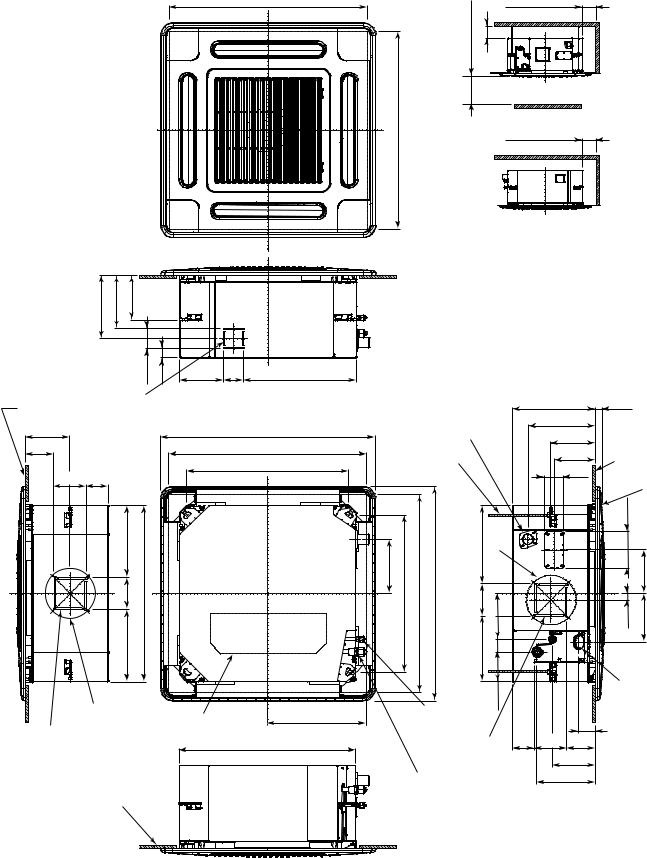
2. CONSTRUCTION VIEWS (EXTERNAL VIEWS)
2-1. Compact 4-way Cassette Type
RAV-SM404MUT , RAV-SM454MUT , RAV-SM564MUT
595 to 660 Ceiling open dimension
595 to 660 Ceiling open dimension
1000 or more |
1000 or more |
15 or more |
|
|
Obustacle |
1000 or more
15 or more
Space required for installation and servicing
207 |
175 |
149 |
|
|
|
|
|
|
64 |
29 |
142 |
64 |
368.5 |
|
|
|
|
Bottom face |
Knockout for flesh |
|
|
of ceiling |
air intake Ø100 |
|
|
145.5 |
|
700 Panel external dimension |
|
93 |
|
595 to 660 Ceiling open dimension |
|
|
|
525 Hanging bolt pitch |
|
105 |
70 |
|
|
|
235 |
dimension |
|
|
105 |
external |
|
|
235 |
575 Unit |
|
|
Ø162 |
Electric parts box |
320.5 |
|
|
||
For branch duct knockout |
|
||
square hole Ø150 |
575 Unit external dimension |
||
Bottom face of ceiling
|
|
|
|
|
268 |
27 |
|
|
|
|
|
|
220.5 |
|
|
|
Drain discharge port |
|
145.5 |
|
|||
|
Hanging bolt |
|
|
|
|
134 |
Bottom face |
|
M10 or W3/8 |
|
|
|
|
63 |
of ceiling |
|
local arrange |
|
|
|
|
Ceiling panel |
|
|
|
|
|
|
|
||
|
|
|
|
|
|
|
|
177 |
Hanging510 bolt pitch Ceiling660to595 open dimension externalPanel700 dimension |
105214 256 |
14842 |
|
|
|
120 |
|
|
|
Wiring158142 |
||||
|
|
|
Ø162 |
|
|
|
|
|
|
|
|
|
|
|
21 |
|
|
|
97.5 |
|
|
|
connection |
|
|
|
|
|
|
port |
|
|
|
|
|
|
|
|
|
|
Refrigerant pipe |
|
|
|
55 |
|
|
|
(Liquid) Ø6.4 |
|
|
|
|
|
|
|
For branch ductt |
70 |
105 |
93 |
|
||
|
knockout square |
|
|
139.5 |
|
||
|
hole Ø150 |
|
|
|
|
|
|
|
|
|
|
190.5 |
|
||
Refrigerant pipe |
|
|
|
|
|||
|
|
|
|
|
|
||
(Gas) Ø12.7 |
|
|
|
|
|
|
|
– 17 –
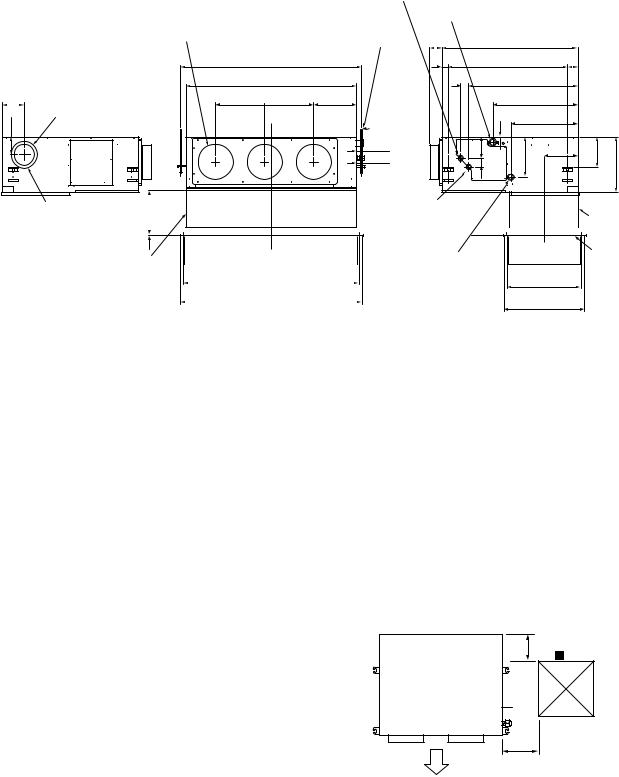
2-2. Concealed Duct Type
RAV-SM564BT , RAV-SM804BT , RAV-SM1104BT , RAV-SM1404BT
|
Refrigerant pipe connecting port |
Drain pipe connecting port |
|
|
||||
|
(Gas side ØF) |
for vinyl chloride pipe |
|
|
|
|||
|
|
Hanging bolt |
(Inner dia. 32, VP. 25) |
|
|
|
||
|
|
|
|
|
|
|
|
|
|
Discharge port flange |
4-M10 screw |
|
|
|
|
|
|
|
N-Ø200 |
(Arranged locally) |
75 |
Main unit dimension 800 |
|
|
||
|
Hanging bolt pitch B |
|
41 |
Hanging bolt pitch 700 59 |
|
|
||
|
Main unit dimension A |
|
50 |
|
638 |
|
|
|
129 |
J = M x K |
H |
|
|
498 |
|
|
|
Knock-out hole Ø125 |
|
|
|
|
|
|||
|
|
|
|
|
393 |
|
|
|
110 |
(Air take-in port) |
|
|
|
41 |
|
|
|
|
|
|
50131 |
|
174 |
320 |
||
|
|
44 |
|
243 |
196 |
|||
|
|
|
|
|
|
|
||
|
|
49 |
|
|
|
|
|
|
|
|
|
|
|
|
|
|
|
6-Ø4 Tapping screw |
to260 |
|
|
|
|
|
|
|
Refrigerant pipe |
|
|
|
Suction port |
|||
undersized hole Ø160 |
|
|
|
|
|
connecting port |
|
|
|
flange |
||||||
|
60 |
|
|
|
|
|
|
|
(Liquid side ØG) |
|
|
|
|
|
(Separate sold) |
|
|
|
|
|
|
|
|
||||||||||
|
|
|
|
|
|
|
|
|
|
|
|
|
|
|
|
|
9
Suction port canvas |
|
C |
||
(Separate sold) |
|
Ceiling open size D |
||
|
|
|
||
|
|
|
|
|
|
|
|
Panel external dimension E |
|
Ø26 Power supply, remote controller cable take-out port
Panel C.L |
410 |
Ceiling open size 470
Panel external dimension 500
Suction port panel (Separate sold)
• Dimension
|
A |
B |
C |
D |
E |
F |
G |
H |
J |
K |
M |
N |
O |
|
|
|
|
|
|
|
|
|
|
|
|
|
|
|
|
SM56 type |
700 |
766 |
690 |
750 |
780 |
12.7 |
6.4 |
252 |
280 |
280 |
1 |
2 |
410 |
|
|
|
|
|
|
|
|
|
|
|
|
|
|
|
|
SM80 type |
1000 |
1066 |
990 |
1050 |
1080 |
15.9 |
9.5 |
252 |
580 |
290 |
2 |
3 |
410 |
|
|
|
|
|
|
|
|
|
|
|
|
|
|
|
|
SM110 type |
1350 |
1416 |
1340 |
1400 |
1430 |
15.9 |
9.5 |
252 |
930 |
310 |
3 |
4 |
410 |
|
SM140 type |
||||||||||||||
|
|
|
|
|
|
|
|
|
|
|
|
|
||
|
|
|
|
|
|
|
|
|
|
|
|
|
|
NOTE 1 :
For maintenance of the equipment, be sure to install a check port A at the position as shown below.
NOTE 2 :
Using the drain up kit sold separately, drain-up by 300 (mm) from drain pipe draw-out port of the main unit is necessary. The drain-up over 300mm or more is impossible.
|
300 |
Check port A |
|
|
|
Plane view of main unit |
|
450 |
|
|
(Pipe side) 
100
Discharge side
– 18 –
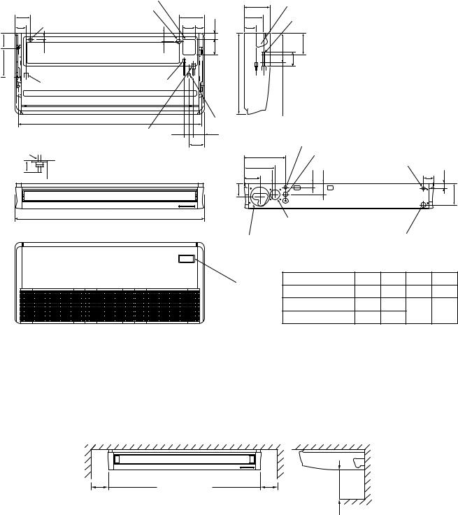
2-3. Ceiling Type
RAV-SM564CT , RAV-SM804CT , RAV-SM1104CT , RAV-SM1404CT
|
|
|
Upper pipe draw-out port (Knockout hole) |
|
|
128 |
Power supply cable take-in port (Knockout) |
216 |
|
|
Remote controller cable takein port |
|||
|
84 |
(Knockout hole) |
|
110 76 |
320 170 |
position) |
53 |
70 |
|
|
(Hanging |
Left drain size |
Refrigerant pipe |
|
|
(Liquid side ØC) |
|
||
|
|
|
||
B (Hanging position)
Refrigerant pipe (Gas side ØD) 75 
 146
146
Hanging bolt |
Ceiling surface |
|
Within 50 |
||
Unit |
||
|
A
|
210 |
Pipe draw-out port (Knockout hole) |
|
|||
|
167 |
|
|
|||
|
|
Drain port VP20 |
|
|||
|
|
|
|
|||
50 |
105 |
|
(Inner dia. Ø26, hose attached) |
|
||
|
|
|
|
|
|
|
130 |
|
|
114 |
|
|
|
|
|
|
41 |
|
|
|
|
680 |
(Liquid pipe) |
(Gas pipe) |
|
|
|
|
|
200 |
216 |
|
|
|
Drain pipe connecting port |
|
|
|
|||
97 |
|
|
|
|
|
|
|
|
|
Remote controller cable takein port |
|
||
|
|
347 |
Power supply cable take-in port (Knockout hole) |
|||
|
262 |
|
|
Remote controller cable takein port |
||
|
|
90 |
32 |
92 |
(Knockout hole) |
32 |
|
135 |
84 |
||||
|
145 |
|
|
|
|
171 |
|
|
Outside air take-in port |
|
|
||
|
|
(Duct sold separately)(Knockout hole Ø92) |
|
|||
|
Pipe hole on wall (Ø100 hole) |
|
Drain left pipe draw-out port (Knockout hole) |
|||
Wireless sensor |
Model name |
A |
B |
C |
D |
|
SM56 type |
910 |
855 |
Ø6.4 |
Ø12.7 |
||
mounting section |
||||||
|
SM80 type |
1180 |
1125 |
Ø9.5 |
Ø15.9 |
|
|
SM110, 140 type |
1595 |
1540 |
|||
|
|
|
250 or more |
or500more |
250 or more |
– 19 –
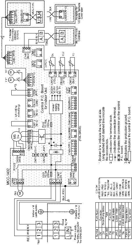
3. WIRING DIAGRAM
3-1. Indoor Unit
3-1-1. Compact 4-way Cassette Type
RAV-SM404MUT , RAV-SM454MUT , RAV-SM564MUT
– 20 –
3-1-2. Concealed Duct Type
RAV-SM564BT , RAV-SM804BT , RAV-SM1104BT , RAV-SM1404BT
– 21 –

3-1-3. Ceiling Type
RAV-SM564CT , RAV-SM804CT , RAV-SM1104CT , RAV-SM1404CT
– 22 –
4. SPECIFICATIONS OF ELECTRICAL PARTS
4-1. Compact 4-way Cassette Type
No. |
Parts name |
Type |
Specifications |
|
|
|
|
1 |
Fan motor (for indoor) |
SWF-230-60-1R |
Output (Rated) 60 W, 220–240 V |
|
|
|
|
2 |
Thermo. sensor (TA-sensor) |
155 mm |
10 kΩ at 25°C |
|
|
|
|
3 |
Heat exchanger sensor (TCJ-sensor) |
Ø6 mm, 1200 mm |
10 kΩ at 25°C |
|
|
|
|
4 |
Heat exchanger sensor (TC-sensor) |
Ø6 mm, 1200 mm |
10 kΩ at 25°C |
|
|
|
|
5 |
Float switch |
FS-0218-102 |
|
|
|
|
|
6 |
Drain pump motor |
ADP-1409 |
|
|
|
|
|
4-2. Concealed Duct Type
No. |
Parts name |
Type |
Specifications |
|
|
|
|
|
|
1 |
Fan motor (SM804BT) |
ICF-280-120-1C |
Output (Rated) 120 W, 220–240 V |
|
|
|
|
|
|
2 |
Fan motor |
ICF-280-120-2C |
Output (Rated) 120 W, 220–240 V |
|
(SM564BT/SM1104BT/SM1404BT) |
||||
|
|
|
||
|
|
|
|
|
3 |
Thermo. sensor (TA-sensor) |
618 mm |
10 kΩ at 25°C |
|
|
|
|
|
|
4 |
Heat exchanger sensor (TCJ-sensor) |
Ø6 mm, 1200 mm |
10 kΩ at 25°C |
|
|
|
|
|
|
5 |
Heat exchanger sensor (TC-sensor) |
Ø6 mm, 1200 mm |
10 kΩ at 25°C |
|
|
|
|
|
|
6 |
Float switch |
FS-0218-102 |
|
|
|
|
|
|
|
7 |
Drain pump motor |
ADP-1409 |
|
|
|
|
|
|
|
8 |
Reactor |
CH-43-2Z-T |
10 mH, 1 A |
|
|
|
|
|
4-3. Ceiling Type
No. |
Parts name |
Type |
Specifications |
|
|
|
|
1 |
Fan motor (SM564CT) |
SWF-280-60-1R |
Output (Rated) 60 W, 220–240 V |
|
|
|
|
2 |
Fan motor (SM804CT) |
SWF-280-60-2R |
Output (Rated) 60 W, 220–240 V |
|
|
|
|
3 |
Fan motor (SM1104CT/SM1404CT) |
SWF-280-120-2R |
Output (Rated) 120 W, 220–240 V |
|
|
|
|
4 |
Thermo. sensor (TA-sensor) |
155 mm |
10 kΩ at 25°C |
|
|
|
|
5 |
Heat exchanger sensor (TCJ-sensor) |
Ø6 mm, 1200 mm |
10 kΩ at 25°C |
|
|
|
|
6 |
Heat exchanger sensor (TC-sensor) |
Ø6 mm, 1200 mm |
10 kΩ at 25°C |
|
|
|
|
7 |
Louver motor |
MP24Z2N |
DC 15V |
|
|
|
|
8 |
Reactor |
CH-43-2Z-T |
10 mH, 1 A |
|
|
|
|
|
|
|
|
– 23 –
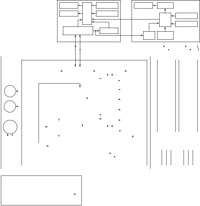
5. CONTROL BLOCK DIAGRAM
5-1. Indoor Controller Block Diagram
5-1-1. In Case of Connection of Wired (Simple) Remote Controller
Wired (Simple) heder remote controller (Max. 2 units) |
Central remote controller |
Display LCD |
|
Function setup |
|
Display LCD |
LCD driver |
Display LED |
CPU |
Key switch |
|
|
Function setup |
|
|
|
CN2 |
|
|
|
|
|
|
CPU |
|
|
|
|
CN1 |
|
|
|
|
|
|
Key switch |
|
|
|
DC5V |
|
|
|
|
|
|
|
|
|
Remote controller |
Power circuit |
|
DC5V |
|
|
communication circuit |
3 |
|
|
||
|
Power |
Secondary |
|||
|
|
|
|
||
|
|
|
|
circuit |
battery |
Indoor unit |
|
|
|
|
|
|
|
|
|
|
|
|
|
#1 (Heder) |
A |
|
B |
#2 |
|
|
#3 |
|
|
|
|||
|
|
(Follower) |
|
|
(Follower) |
|
|
|
|||||
|
|
|
|
|
|
|
|
|
|||||
|
|
|
|
|
A |
|
B |
|
|
A |
|
B |
|
Indoor control P.C. board (MCC-1402)
|
|
|
|
|
|
|
|
|
|
|
|
|
|
|
|
DC20V |
|
Remote controller |
|
|
|
|
|
|
|
|
|
|
|
|
|
|
|
|
|
EEPROM |
|
|
|
|
|
|
|
|
|
|
|
|
|
|
|
|
||||||||||||||||
|
|
|
|
|
|
|
|
|
|
|
|
|
|
|
|
|
|
|
|
|
|
|
|
communication circuit |
|
|
|
|
|
|
|
|
|
|
|
|
|
|
|
|
|
|
|
|
|
|
|
|
|
|
|
|
|
|
|
|
||||||||||||
|
|
|
|
|
|
|
|
|
|
|
|
|
|
|
|
|
|
|
|
|
|
|
|
|
|
|
|
|
|
|
|
|
|
|
|
|
|
|
|
|
|
|
|
|
|
|
|
|
|
|
|
|
|
|
|
|
|
|
||||||||||
|
*None for |
|
|
|
|
|
|
|
DC5V |
|
|
|
|
|
|
|
|
|
|
|
|
|
|
|
|
|
|
|
|
|
|
|
|
|
|
|
|
|
|
|
|
|
|
|
|
|
|
|
|
|
|
|
|
|
||||||||||||||
|
|
|
|
|
|
|
|
|
|
|
|
|
|
|
|
|
|
|
|
|
|
|
|
|
|
|
|
|
|
|
|
|
|
|
|
|
|
|
|
|
|
|
|
|
|
|
|
|
|
|
|
|
||||||||||||||||
|
|
|
|
|
|
|
|
|
|
|
|
|
|
|
|
|
|
|
|
|
|
|
|
|
|
|
|
|
|
|
|
|
|
|
|
|
|
|
|
|
|
|
|
|
|
|
|
|
|
|
|
|
||||||||||||||||
|
|
|
|
|
|
|
|
DC12V |
|
|
|
|
|
|
|
|
|
|
|
|
|
|
|
|
|
|
|
|
|
|
|
|
|
TA sensor |
|
|
|
|
|
|
|
|
|
|
|
|
|
|
|
|||||||||||||||||||
|
|
|
|
|
|
|
|
|
|
|
|
|
|
|
|
|
|
|
|
|
|
|
|
|
|
|
|
|
|
|
|
|
|
|
|
|
|
|
|
|
|
|||||||||||||||||||||||||||
|
Duct type |
|
|
|
|
|
|
|
|
|
|
|
|
|
|
|
|
|
|
|
|
|
|
|
|
|
|
|
|
|
|
|
|
|
|
|
|
|
|
|
|
|
|
|
|
|
|
|
|
|
|
|
|
|
|
|
|
|
|
|
|
|||||||
|
|
|
|
|
|
|
|
|
|
|
|
|
|
|
|
|
|
|
|
|
|
|
|
|
|
|
|
|
|
|
|
|
|
|
|
|
|
|
|
|
|
|
|
|
|
|
|
|
|
|
|
|
|
|
|
|
|
|
|
|||||||||
|
|
|
|
|
|
|
|
|
|
|
|
|
|
|
|
|
|
|
|
|
|
|
|
|
|
|
|
|
|
|
|
|
|
|
|
|
|
|
|
|
|
|
|
|
|
|
|
|
|
|
|
|
|
|
|
|
|
|
|
|
||||||||
|
Louver |
|
|
|
|
|
|
|
|
|
|
|
|
|
|
|
|
|
|
|
|
|
|
|
|
|
|
|
|
|
|
|
|
|
|
|
|
|
|
|
|
|
TC sensor |
|
|
|
|
|
|
|
|
|
|
|
|
|
|
|
||||||||||
|
|
|
|
|
|
|
|
|
|
|
|
|
|
|
|
|
|
|
|
|
|
|
|
|
|
|
|
|
|
|
|
|
|
|
|
|
|
|
|
|
|
|
|
|
|
|
|
|
|
|
||||||||||||||||||
|
motor |
|
|
|
|
|
|
|
|
|
|
|
|
|
|
|
|
|
|
|
|
|
|
|
|
|
|
|
|
|
|
|
|
|
|
|
|
|
|
|
|
|
|
|
|
|
|
|
|
|
|
Same as left |
Same as left |
|||||||||||||||
|
|
|
|
|
|
|
|
|
|
|
|
|
|
|
|
|
|
|
|
|
|
|
|
|
|
|
|
|
|
|
|
|
|
|
|
|
|
|
|
|
|
|
|
|
|
|
|
|
|
|||||||||||||||||||
|
|
|
|
|
|
|
|
|
|
|
|
|
|
|
|
|
|
|
|
|
|
|
|
|
|
|
|
|
|
|
|
|
|
|
|
|
|
|
|
|
|
|
|
|
|
|
|
|
|
|
|
|
|
|
|
|||||||||||||
|
|
|
|
|
|
|
|
|
|
|
|
|
|
|
|
|
|
|
|
|
|
|
|
|
|
|
|
Driver |
|
|
|
|
|
|
|
|
|
|
|
|
|
|
|
|
|
|
|
|
|
|
|
|
|
|
2 |
|
|
|
|
2 |
|
|
|
|
||||
|
|
|
|
|
|
|
|
|
|
|
|
|
|
|
|
|
|
|
|
|
|
|
|
|
|
|
|
|
|
|
|
|
|
|
CPU |
|
|
|
|
|
|
|
TCJ sensor |
|
|
|
|
|
|
|
|
|
|
|||||||||||||||
|
|
|
|
|
|
|
|
|
|
|
|
|
|
|
|
|
|
|
|
|
|
|
|
|
|
|
|
|
|
|
|
|
|
|
|
|
|
|
|
|
|
|
|
|
|
|
|
|
||||||||||||||||||||
|
|
|
|
|
|
|
|
|
|
|
|
|
|
|
|
|
|
|
|
|
|
|
|
|
|
|
|
|
|
|
|
|
|
|
|
|
|
|
|
|
|
|
|
|
|
|
|
|
|
|
|
|
|
|
|
|||||||||||||
|
|
|
|
|
|
|
|
|
|
|
|
|
|
|
|
|
|
|
|
|
|
|
|
|
|
|
|
|
|
|
|
|
|
|
|
|
|
|
|
|
|
|
|
|
|
|
|
|
|
|
|
|
|
|
|
|
|
|
|
|||||||||
|
Drain |
|
|
|
|
|
|
|
|
|
|
|
|
|
|
|
|
|
|
|
|
|
|
|
|
|
|
|
|
|
H8/3039 |
|
|
|
|
|
|
|
|
|
|
|
|
|
|
|
|
|
|
|
|
|
|
|
|
|
|
|||||||||||
|
|
|
|
|
|
|
|
|
|
|
|
|
|
|
|
|
|
|
|
|
|
|
|
|
|
|
|
|
|
|
|
|
|
|
|
|
|
|
|
|
|
|
|
|
|
|
|
|
|
|
|
|
|
|
|
|||||||||||||
|
|
|
|
|
|
|
|
|
|
|
|
|
|
|
|
|
|
|
|
|
|
|
|
|
|
|
|
|
|
|
|
|
|
|
|
|
|
|
|
|
|
|
|
|
|
|
|
|
|
|
|
|
|
|
|
|
|
|
|
|
||||||||
|
pump |
|
|
|
|
|
|
|
|
|
|
|
|
|
|
|
|
|
|
|
|
|
|
|
|
|
|
|
|
|
|
|
|
|
|
|
|
|
|
|
|
|
|
|
|
|
|
|
|
|
|
|
|
|
|
|
|
|
|
|
|
|
|
|
|
|||
|
*Option for |
|
|
|
|
|
|
|
|
|
|
|
|
|
|
|
|
|
|
|
|
|
|
|
|
|
|
|
|
|
|
|
|
|
|
|
|
|
|
|
|
|
Float input |
|
|
|
|
|
|
|
|
|
|
|
|
|
|
|
||||||||||
|
|
|
|
|
|
|
|
|
|
|
|
|
|
|
|
|
|
|
|
|
|
|
|
|
|
|
|
|
|
|
|
|
|
|
|
|
|
|
|
|
|
|
|
|
|
|
|
|
|
|
|
|
|
|
|
|
|
|
|
|
||||||||
|
|
|
|
|
|
|
|
|
|
|
|
|
|
|
|
|
|
|
|
|
|
|
|
|
|
|
|
|
|
|
|
|
|
|
|
|
|
|
|
|
|
|
|
|
|
|
|
|
|
|
|
|
|
|
|
|
|
|
|
|||||||||
|
Ceiling type |
|
|
|
|
|
|
|
|
|
|
|
|
|
|
|
|
|
|
|
|
|
|
|
|
|
|
|
|
|
|
|
|
|
|
|
|
|
|
|
|
|
|
|
|
|
|
|
|
|
|
|
|
|
|
|
|
|
|
|
|
|||||||
|
|
|
|
|
|
|
|
|
|
|
|
|
|
|
|
|
|
|
|
|
|
|
|
|
|
|
External |
|
|
|
|
|
|
|
|
|
|
|
|
|
|
|
|
|
|
|
|
|
HA |
|
|
|
|
|
|
|
|
|
|
|
|
|
|
|
||||
|
|
|
|
|
|
|
|
|
|
|
|
|
|
|
|
|
|
|
|
|
CPU |
|
|
|
|
|
|
|
|
|
|
|
|
|
|
|
|
|
|
|
|
|
|
|
|
|
|
|
|
|
|
|
|
|
|
|
|
|
|
|
|
|
||||||
|
Indoor |
|
|
|
|
|
|
|
|
|
|
|
|
|
|
output |
|
|
|
|
|
|
|
|
|
|
|
|
|
|
|
|
|
|
|
|
|
|
|
|
|
|
|
|
|
|
|
|
|
|
|
|
|
|
|
|||||||||||||
|
|
|
|
|
|
|
|
|
|
|
|
|
|
|
|
|
|
|
|
|
|
|
|
|
|
|
|
|
|
|
|
|
|
|
|
|
|
|
|
|
|
|
|
|
|
|
|
|
|
|
||||||||||||||||||
fan motor |
|
|
|
|
|
|
|
|
|
|
|
|
|
TMP88CH47FG |
|
|
|
|
|
|
|
|
|
|
|
|
|
|
|
|
|
|
|
|
|
|
|
Serial send/ |
|
|
|
|
|
|
|
|
|
|
|
|
|
|
|
|
||||||||||||||
|
|
|
|
|
|
|
|
|
|
|
|
(TMP88PH47FG) |
|
|
|
Run |
|
|
|
|
|
|
|
|
|
|
|
|
|
|
|
|
|
|
|
|
|
|
|
|
|
|
|
|
|
|
|
|
||||||||||||||||||||
|
|
|
|
|
|
|
|
|
|
|
|
|
|
|
|
|
|
|
|
|
|
|
|
|
|
|
|
|
|
|
|
|
|
|
|
|
|
|
|
|
|
|
|
|
|
|
|
|
|
|
|
|
|
|||||||||||||||
|
|
|
|
|
|
|
|
|
|
|
|
|
|
|
|
|
|
|
|
|
|
|
|
|
|
|
|
|
Alarm |
|
|
|
|
|
|
|
|
|
|
|
|
|
receive circuit |
|
|
|
|
|
|
|
|
|
|
|
|
|
|
|
|
|||||||||
|
|
|
|
|
|
|
|
|
|
|
|
|
|
|
|
|
|
|
|
|
|
|
|
|
|
|
|
|
Defrost |
|
|
|
|
|
|
|
|
|
|
|
|
|
|
|
|
|
|
|
|
1 |
|
2 |
3 |
|
|
1 |
|
2 |
|
3 |
|
|||||||
|
|
|
|
|
|
|
|
|
|
|
|
|
|
|
|
|
|
|
|
|
|
|
|
|
|
|
|
Thermo. ON |
|
|
|
|
|
|
AC |
|
|
|
|
|
|
|
|
|
|
|
|
|
|
|
|
|
|
|
|
|
|
|
|
|
|
|||||||
|
|
|
|
|
|
|
|
|
|
|
|
|
|
|
|
|
|
|
|
|
Fan motor |
|
|
|
|
COOL |
|
|
|
|
|
|
|
|
|
|
|
|
|
|
|
|
|
|
|
|
|
|
|
|
|
|
|
|
|
|
|
|
||||||||||
|
|
|
|
|
|
|
|
|
|
|
|
|
|
|
|
|
|
|
|
|
|
|
|
|
|
|
|
|
|
|
|
|
|
|
|
|
|
|
|
|
|
|
|
|
|
|
|
|
|
|
|
|
|
|
||||||||||||||
|
|
|
|
|
|
|
|
|
|
|
|
|
|
|
|
|
|
|
|
|
|
|
|
|
HEAT |
|
|
|
|
|
synchronous |
|
|
|
|
|
|
|
|
|
|
|
|
|
|
|
|
|
|
|
|
|
||||||||||||||||
|
|
|
|
|
|
|
|
|
Power circuit |
|
|
|
|
|
control circuit |
|
|
|
FAN |
|
|
|
|
signal input circuit |
|
|
|
|
|
|
|
|
|
|
|
|
|
|
|
|
|
|
|
|
|
|||||||||||||||||||||||
|
|
DC280V |
|
|
|
|
|
|
|
|
|
|
|
|
|
|
|
|
|
|
|
|
|
|
|
|
|
|
|
|
|
|
|
|
|
|
|
|
|
|||||||||||||||||||||||||||||
|
|
|
|
|
|
|
|
|
|
|
|
|
|
|
|
|
|
|
|
|
|
|
|
|
|
|
|
|
|
|
|
|
|
|
|
|
|
|
|
|
|
|
|
|
|
|
|
|
|
|
|
|
|
|
|
|
|
|
|
|
|
|
||||||
|
|
|
|
|
|
|
|
|
|
|
|
|
|
|
|
|
|
|
|
|
|
|
|
|
|
|
|
|
|
|
|
|
|
|
|
|
|
|
|
|
|
|
|
|
|
|
|
|
|
|
|
|
|
|
|
|
|
|
|
|
|
|
|
|
|
|
|
|
|
|
|
|
|
|
|
|
|
|
|
|
|
|
|
|
|
|
|
|
|
|
|
|
|
|
|
|
|
|
|
|
|
|
|
|
|
|
|
|
|
|
|
|
|
|
|
|
|
|
|
|
|
|
|
|
|
|
|
|
|
|
|
|
|
|
|
|
|
|
|
|
|
|
|
|
|
|
|
|
|
|
|
|
|
|
|
|
|
|
|
|
|
|
|
|
|
|
|
|
|
|
|
|
1 |
2 |
|
3 |
|
|
|
|
|
|
|
|
|
|
|
|
|
|
|
|
|
|
|
|
|
|
|
|
|
|||||
|
|
|
|
|
|
|
|
|
|
|
|
|
|
|
|
|
|
|
|
|
|
|
|
|
|
|
|
|
|
|
|
|
|
|
|
|
|
|
|
|
|
|
|
|
|
|
|
|
|
|
|
|
|
|
|
Outdoor unit |
Outdoor unit |
|||||||||||
|
|
|
|
|
|
|
|
|
|
|
|
|
|
|
|
|
|
|
|
|
|
|
|
|
|
|
|
|
|
|
|
|
|
|
|
|
|
|
|
|
|
|
|
|
|
|
|
|
|
|
|
|
|
|
|
|||||||||||||
“1:1 model” connection interface (Option) |
|
|
|
|
|
|
|
|
|
|
|
|
|
|
|
|
|
|
|
|
|
|
|
|
|
Up to 8 units are connectable. 1 |
|
|
|
|
|
|
|
|||||||||||||||||||||||||||||||||||
|
|
|
|
|
|
|
|
|
|
|
|
|
|
|
|
|
|
|
|
|
|
|
|
|
1 |
However, if “1:1 model connection interface” is |
|
|
||||||||||||||||||||||||||||||||||||||||
|
|
|
|
|
|
|
|
|
|
|
|
|
|
|
|
|
|
|
|
|
|
|
|
|
|
|
|
|
|
|
|
|
|
|
|
|
|
|
|
|
|
|
|
|
|
|
|
|
|
|
|
|||||||||||||||||
|
|
|
|
|
|
|
|
|
|
|
|
|
|
|
|
|
|
|
|
|
P.C. board |
|
|
|
|
|
|
|
|
|
|
|
|
|
|
|
|
|
|
|
|
|
|
|
|
|
|
|
connected when 2 wired (simple) remote controllers |
|||||||||||||||||||
|
|
|
|
|
|
|
|
|
|
|
|
|
|
|
|
|
|
|
|
|
|
|
|
|
|
|
|
|
|
|
1 |
2 |
|
3 |
|
|
|
|
|
|
|
|
are connected, Max. 7 units are connectable. |
|
|
|||||||||||||||||||||||
|
|
|
|
|
|
|
|
|
|
|
|
|
|
|
|
|
|
|
|
|
(MCC-1440) |
|
|
|
|
|
|
|
|
|
|
|
|
|
|
|
|
2 |
Connect “1:1 model connection interface” to only |
|||||||||||||||||||||||||||||
|
Central remote |
|
|
|
U3 |
|
|
|
|
|
|
|
|
|
|
|
|
|
|
|
|
|
|
|
|
|
|
|
|
|
|
|
|
|
|
|
|
|
|
|
||||||||||||||||||||||||||||
|
|
|
|
|
|
|
|
|
|
TCC-LINK |
|
|
|
|
|
|
|
|
|
|
|
|
|
|
|
|
|
|
|
|
|
|
|
|
|
|
|
1 unit and connect 1 “1:1 model connection |
|
|
|
|
||||||||||||||||||||||||||
|
|
|
|
|
|
|
|
|
|
|
|
|
|
|
|
|
|
|
|
|
|
|
|
|
|
|
|
|
|
|
|
|
|
|
|
|
|
|
|
|
|
|
|
|||||||||||||||||||||||||
|
|
|
|
|
|
|
|
|
|
|
|
|
|
|
|
|
|
|
|
|
|
|
|
|
|
|
|
|
|
|
|
|
|
|
|
|
|
|
|
|
|
|
|
|||||||||||||||||||||||||
|
controller(Option) |
|
|
|
|
|
|
|
communication circuit |
|
|
|
|
|
|
|
|
|
|
|
|
|
|
|
|
|
|
|
|
|
|
interface” to the header unit. |
|
|
|
|
|
|
|
|
|
|||||||||||||||||||||||||||
|
|
|
U4 |
|
|
|
|
|
|
|
|
|
|
|
|
|
|
|
|
|
|
|
|
|
|
|
|
3 |
|
|
|
|
|
|
|
|
|
|||||||||||||||||||||||||||||||
|
|
|
|
|
|
|
|
|
|
|
|
|
|
|
|
|
|
|
|
|
|
|
|
|
|
|
|
|
|
|
|
|
|
|
|
|
|
|
|
|
|
|
|
|
|
|
It is unavailable to connect the Central remote |
|
|
|||||||||||||||||||
|
|
|
|
|
|
|
|
|
|
|
|
|
|
|
|
|
|
|
|
|
|
|
|
|
|
|
|
|
|
|
|
|
|
|
|
|
|
|
|
|
|
|
|
|
|
|
|
|
|
|
|
|||||||||||||||||
|
|
|
|
|
|
|
|
|
|
|
|
|
|
|
|
|
|
|
|
|
|
|
|
|
|
|
|
|
|
|
|
|
|
|
|
|
|
|
|
|
|
|
|
|
|
|
|
|
|
|
|
|||||||||||||||||
|
|
|
|
|
|
|
|
|
|
|
|
|
|
|
|
|
|
|
|
|
|
|
|
|
|
|
|
|
|
|
|
|
|
|
|
|
|
|
|
|
|
|
|
|
|
|
|
|
|
|
|
controller to the simple wired remote controller. |
|
|
||||||||||||||
|
|
|
|
|
|
|
|
|
|
|
|
|
|
|
|
|
|
|
|
|
|
|
|
|
|
|
|
|
|
|
|
|
|
|
|
|
|
|
|
|
|
|
|
|
|
|
|
|
|
|
|
|
|
|||||||||||||||
|
|
|
|
|
|
|
|
|
|
|
|
|
|
|
|
|
|
|
|
|
|
|
|
|
|
|
|
|
|
|
|
|
|
|
|
|
|
Outdoor unit |
|
|
|
|
|
|
|
|
|
|
|
|
|
|
|
|
|
|||||||||||||
– 24 –
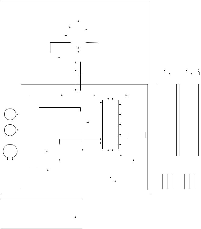
5-1-2. In Case of Connection of Wireless Remote Controller
Indoor unit #1 (Heder)
|
|
|
|
Wireless remote controller |
|
|
|
|
|
|
|
|
|
|
|
|
||||||||||||||
|
|
|
|
|
|
|
|
|
|
|
|
|
|
|
|
|||||||||||||||
|
Receiver P.C. board (MCC-1504) |
|
|
|
|
|
|
|
|
|
|
|
|
|||||||||||||||||
|
|
|
|
|
|
|
|
|
|
|
|
|
|
|
|
|
|
|
|
|
|
|
|
|
|
|||||
|
|
|
|
|
|
|
Display LED |
|
|
|
|
|
|
|
|
|
|
|
|
|
|
|
||||||||
|
|
|
|
|
|
|
|
|
|
|
|
|
|
|
|
|
|
|
|
|
|
|
|
|
|
|
|
|
|
|
|
|
|
|
|
|
|
|
|
|
|
|
|
|
|
|
|
|
|
|
|
|
|
|
|
|
|
|
|
|
|
|
|
|
|
|
|
|
|
|
|
|
|
|
|
|
|
|
|
|
|
|
|
|
|
|
|
|
|
|
|
|
|
Receive circuit |
|
|
|
|
|
|
|
|
|
|
|
|
|
|
|
|
|
|
|
|
|
|
|
|
|
|
|
||
|
|
|
|
|
|
|
|
|
|
|
|
|
|
Function setup SW |
|
|
|
|
|
|
|
|
|
|
|
|
||||
|
|
|
|
|
|
|
|
|
|
|
|
|
|
|
|
|
|
|
|
|
|
|
|
|
|
|
|
|
||
|
|
|
|
|
|
|
|
|
|
|
|
|
|
|
|
|
|
|
|
|
|
|
|
|
|
|
|
|||
|
|
|
|
|
|
|
|
|
|
|
|
|
|
|
|
|
|
|
|
|
|
|
|
|
|
|
|
|||
|
Buzzer |
|
|
|
|
|
CPU |
|
|
|
|
|
|
|
|
|
|
|
|
|
|
|
|
|
||||||
|
|
|
|
|
|
|
|
|
|
|
|
|
|
|
|
|
|
|||||||||||||
|
|
|
|
|
|
|
|
|
|
|
|
|
|
|
|
|
|
|
|
|
|
|
|
|
|
|
|
|
|
|
|
|
|
|
|
|
|
|
|
|
|
|
|
|
|
|
|
|
Temporary |
|
|
|
|
|
|
|
|
|
|
|
|
|
|
|
|
|
|
|
|
|
|
|
|
|
|
|
|
|
|
operation SW |
|
|
|
|
|
|
|
|
|
|
|
|
|
DC5V |
|
|
|
|
|
|
|
|
|
|
|
|
|
|
|
|
|
|
|
|
|
|
|
|
|
|
|
||
|
|
|
|
|
|
|
|
|
|
|
|
|
|
|
|
|
|
|
|
|
|
|
|
|
|
|
|
|||
|
|
|
|
|
|
|
|
|
|
|
|
|
|
|
|
|
|
|
|
|
|
|
|
|
|
|
|
|||
|
|
|
|
|
|
|
|
|
|
|
|
|
|
|
|
|
|
|
|
|
|
|
|
|
|
|
|
|||
|
|
|
|
|
|
|
|
|
|
|
|
|
|
|
|
|
|
|
|
|
|
|
|
|
||||||
|
Power |
|
|
|
Remote controller |
|
|
|
|
|
|
|
|
|
|
|
|
|
|
|||||||||||
|
circuit |
|
|
|
communication circuit |
|
|
|
|
|
|
|
|
|
|
|
|
|
|
|||||||||||
|
|
|
|
|
|
|
|
|
|
|
|
|
|
|
|
|
|
|
|
|
|
|
|
|
|
|
|
|||
|
|
|
|
|
|
|
|
|
|
|
|
|
|
|
|
|
|
|
|
|
|
|
|
|
|
|
|
|
|
|
|
|
|
|
|
|
|
|
|
|
|
|
|
|
|
|
|
|
|
|
|
|
|
|
|
|
|
|
|
|
|
|
|
|
|
|
|
|
|
|
|
|
|
|
|
|
|
|
|
|
|
|
|
|
|
|
|
|
|
|
|
|
|
|
|
|
|
|
|
|
|
|
|
|
|
|
|
|
|
|
|
#2 |
|
|
#3 |
|
|
|
|||||
|
|
|
|
|
|
|
|
A |
|
|
|
B |
|
|
(Follower) |
|
|
(Follower) |
|
|
|
|||||||||
|
|
|
|
|
|
|
|
|
|
|
|
|
|
A |
|
B |
|
|
A |
|
B |
|
||||||||
Indoor control P.C. board (MCC-1402)
|
|
|
|
DC20V |
|
Remote controller |
|
|
|
|
|
|
|
|
|
|
EEPROM |
|
|
|||
|
|
|
|
|
|
communication circuit |
|
|
|
|
|
|
|
|
|
|
|
|
||||
|
|
|
|
|
|
|
|
|
|
|
|
|
|
|
|
|||||||
* None for |
DC5V |
|
|
|
|
|
|
|
|
|
|
|
|
|
|
|
|
|
|
|||
|
|
|
|
|
|
|
|
|
|
|
|
|
|
|
|
|
|
|||||
|
|
|
|
|
|
|
|
|
|
|
|
|
|
|
|
|
|
|||||
DC12V |
|
|
|
|
|
|
|
|
|
|
|
|
|
|
|
TA sensor |
|
|
||||
Duct type |
|
|
|
|
|
|
|
|
|
|
|
|
|
|
|
|
|
|||||
|
|
|
|
|
|
|
|
|
|
|
|
|
|
|
|
|
|
|
||||
Louver |
|
|
|
|
|
|
|
|
|
|
|
|
|
|
|
|
|
|
|
|
||
|
|
|
|
|
|
|
|
|
|
|
|
|
|
|
|
TC sensor |
|
|
||||
motor |
|
|
|
|
|
|
|
|
|
|
|
|
|
|
|
|
Same as left |
Same as left |
||||
|
|
|
|
|
|
|
|
|
|
|
|
|
|
|
|
|
||||||
|
|
|
|
|
|
|
|
|
|
|
|
|
|
|
|
|
|
|
|
|
||
|
|
|
|
|
|
|
Driver |
|
|
|
|
|
|
|
|
|
|
|
|
|
2 |
2 |
|
|
|
|
|
|
|
|
|
|
|
|
|
|
CPU |
|
|
TCJ sensor |
|
|
|||
|
|
|
|
|
|
|
|
|||||||||||||||
Drain |
|
|
|
|
|
|
|
|
|
|
H8/3039 |
|
|
|
|
|
||||||
|
|
|
|
|
|
|
|
|
|
|
|
|
|
|
||||||||
|
|
|
|
|
|
|
|
|
|
|
|
|
|
|
|
|
|
|
||||
pump |
|
|
|
|
|
|
|
|
|
|
|
|
|
|
|
|
|
|
|
|
|
|
|
|
|
|
|
|
|
|
|
|
|
|
|
|
|
|
|
|
Float input |
|
|||
|
|
|
|
|
|
|
|
|
|
|
|
|
|
|
|
|
|
|
|
|
||
|
|
|
|
|
|
|
|
|
|
|
|
|
|
|
|
|
|
|
|
|
||
*Option for Ceiling type
|
|
|
|
|
|
|
|
|
|
|
|
|
|
|
|
|
|
|
|
|
External |
|
|
|
|
|
|
|
|
|
|
|
|
|
HA |
|
|
|
|
|
|
|
|
|
|
|
|
|
|
|
|||||
|
|
|
|
|
|
|
|
|
|
|
|
|
|
|
|
|
CPU |
|
|
|
|
|
|
|
|
|
|
|
|
|
|
|
|
|
|
|
|
|
|
|
|
|
|
|
|
|
|
||||||||
|
Indoor |
|
|
|
|
|
|
|
|
|
|
|
|
output |
|
|
|
|
|
|
|
|
|
|
|
|
|
|
|
|
|
|
|
|
|
|
|
|
|
|
|
|
|
||||||||||||
|
|
|
|
|
|
|
|
|
|
|
TMP88CH47FG |
|
|
|
|
|
|
|
|
|
|
|
|
|
|
|
|
|
|
|
|
|
|
|
|
|
|
|
|
|
|
||||||||||||||
fan motor |
|
|
|
|
|
|
|
|
|
|
|
(TVP88PH47FG) |
|
|
|
|
|
Run |
|
|
|
|
|
|
|
|
|
|
|
|
Serial send/ |
|
|
|
|
|
|
|
|
|
|
|
|
|
|
|
|||||||||
|
|
|
|
|
|
|
|
|
|
|
|
|
|
|
|
|
|
|
|
|
|
|
|
|
|
|
|
|
|
|
|
|
|
|
|
|
|
|
|
|
|
|
|
|
|
|
|
||||||||
|
|
|
|
|
|
|
|
|
|
|
|
|
|
|
|
|
|
|
|
|
|
|
|
|
Alarm |
|
|
|
|
|
|
|
|
|
|
|
|
receive circuit |
|
|
|
|
|
|
|
|
|
|
|
|
|
|
|
||
|
|
|
|
|
|
|
|
|
|
|
|
|
|
|
|
|
|
|
|
|
|
|
|
|
Defrost |
|
|
|
|
|
|
|
|
|
|
|
|
|
|
|
1 |
2 |
|
3 |
|
|
1 |
|
2 |
3 |
|
||||
|
|
|
|
|
|
|
|
|
|
|
|
|
|
|
|
|
|
|
|
|
|
|
Thermo. ON |
|
|
|
|
|
|
AC |
|
|
|
|
|
|
|
|
|
|
|
|
|
|
|
|
|
|
|
|
|
|
|||
|
|
|
|
|
|
|
|
|
|
|
|
|
|
|
|
|
Fan motor |
|
|
|
|
|
COOL |
|
|
|
|
|
|
|
|
|
|
|
|
|
|
|
|
|
|
|
|
|
|
|
|
|
|
|
|
||||
|
|
|
|
|
|
|
|
|
|
|
|
|
|
|
|
|
|
|
|
|
|
|
|
|
|
|
|
|
|
|
|
|
|
|
|
|
|
|
|
|
|
|
|
|
|
|
|
||||||||
|
|
|
|
|
|
|
|
|
|
|
|
|
|
|
|
|
|
|
|
|
|
HEAT |
|
|
|
|
synchronous |
|
|
|
|
|
|
|
|
|
|
|
|
|
|
|
|
|
|
||||||||||
|
|
|
|
|
|
|
Power circuit |
|
|
|
|
control circuit |
|
|
|
|
|
FAN |
|
|
|
signal input circuit |
|
|
|
|
|
|
|
|
|
|
|
|
|
|
|
|
|
|
|||||||||||||||
|
|
DC280V |
|
|
|
|
|
|
|
|
|
|
|
|
|
|
|
|
|
|
|
|
|
|
|
|
|
|
|
|
|
|
|
|
|
|
|||||||||||||||||||
|
|
|
|
|
|
|
|
|
|
|
|
|
|
|
|
|
|
|
|
|
|
|
|
|
|
|
|
|
|
|
|
|
|
|
|
|
|
|
|
|
|
|
|
|
|
|
|
|
|
|
|
||||
|
|
|
|
|
|
|
|
|
|
|
|
|
|
|
|
|
|
|
|
|
|
|
|
|
|
|
|
|
|
|
|
|
|
|
|
|
|
|
|
|
|
|
|
|
|
|
|
|
|
|
|
|
|
|
|
|
|
|
|
|
|
|
|
|
|
|
|
|
|
|
|
|
|
|
|
|
|
|
|
|
|
|
|
|
|
|
|
|
|
|
|
|
|
|
|
|
|
|
|
|
|
|
|
|
|
|
|
|
|
|
|
|
|
|
|
|
|
|
|
|
|
|
|
|
|
|
|
|
|
|
|
|
|
|
|
|
|
|
1 |
2 |
3 |
|
|
|
|
|
|
|
|
|
|
|
|
|
|
|
|
|
|
|
|
|
|||||
|
|
|
|
|
|
|
|
|
|
|
|
|
|
|
|
|
|
|
|
|
|
|
|
|
|
|
|
|
|
|
|
|
|
|
|
|
|
|
|
|
|
|
|
Outdoor unit |
Outdoor unit |
||||||||||
|
|
|
|
|
|
|
|
|
|
|
|
|
|
|
|
|
|
|
|
|
|
|
|
|
|
|
|
|
|
|
|
|
|
|
|
|
|
|
|
|
|
|
|
||||||||||||
“1:1 model” connection interface (Option) |
|
|
|
|
|
|
|
|
|
|
|
|
|
|
|
|
|
|
|
Up to 8 units are connectable. 1 |
|
|
|
|
|
|
|||||||||||||||||||||||||||||
|
|
|
|
|
|
|
|
|
|
|
|
|
|
|
|
|
|
|
1 However, if “1:1 model connection interface” is |
||||||||||||||||||||||||||||||||||||
|
|
|
|
|
|
|
|
|
|
|
|
|
|
|
|
|
|
|
|
|
|
|
|
|
|
|
|
|
|
|
|
|
|
|
|
|
|
|
|||||||||||||||||
|
|
|
|
|
|
|
|
|
|
|
|
|
|
|
|
|
P.C. board |
|
|
|
|
|
|
|
|
|
|
|
|
|
|
|
|
|
|
|
|
connected when 2 wireless remote controllers are |
|||||||||||||||||
|
|
|
|
|
|
|
|
|
|
|
|
|
|
|
|
|
|
|
|
|
|
|
|
|
|
|
|
|
|
|
|
|
|
|
|
|
connected, Max. 7 units are connectable. |
|
|
|
|||||||||||||||
|
|
|
|
|
|
|
|
|
|
|
|
|
|
|
|
|
(MCC-1440) |
|
|
|
|
|
|
|
1 |
2 |
3 |
|
|
|
|
|
|
|
|
||||||||||||||||||||
|
Central remote |
|
|
U3 |
|
|
|
|
|
|
TCC-LINK |
|
|
|
|
|
|
|
|
|
|
|
|
|
|
|
|
|
|
|
2 Connect “1:1 model connection interface” to only |
||||||||||||||||||||||||
|
|
|
|
|
|
|
|
|
|
|
|
|
|
|
|
|
|
|
|
|
|
|
|
|
|
|
|
|
1 unit and connect 1 “1:1 model connection |
|
|
||||||||||||||||||||||||
|
controller (Option) |
|
|
|
|
|
|
|
|
|
|
|
|
|
|
|
|
|
|
|
|
|
|
|
|
|
|
|
|
|
|
|
|||||||||||||||||||||||
|
|
|
|
|
|
communication circuit |
|
|
|
|
|
|
|
|
|
|
|
|
|
|
|
|
|
|
|
||||||||||||||||||||||||||||||
|
|
U4 |
|
|
|
|
|
|
|
|
|
|
|
|
|
|
|
|
|
|
|
interface” to the header unit. |
|
|
|
|
|
|
|
|
|||||||||||||||||||||||||
|
|
|
|
|
|
|
|
|
|
|
|
|
|
|
|
|
|
|
|
|
|
|
|
|
|
|
|
|
|
|
|
|
|
|
|
|
|
|
|
|
|
|
|
|
|
||||||||||
|
|
|
|
|
|
|
|
|
|
|
|
|
|
|
|
|
|
|
|
|
|
|
|
|
|
|
|
|
|
|
|
|
|
|
|
|
|
|
|
|
|
|
|
|
|
|
|
|
|
|
|
|
|
|
|
|
|
|
|
|
|
|
|
|
|
|
|
|
|
|
|
|
|
|
|
|
|
|
|
|
|
|
|
|
|
|
|
|
|
|
|
|
|
|
|
|
|
|
|
|
|
|
|
|
|
|
|
|
|
|
|
|
|
|
|
|
|
|
|
|
|
|
|
|
|
|
|
|
|
|
|
|
|
|
|
|
|
|
|
|
|
|
|
|
|
|
|
|
|
|
|
|
|
|
|
|
|
|
|
|
|
|
|
|
|
|
|
Outdoor unit
– 25 –
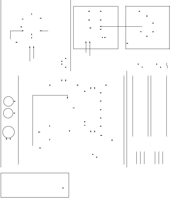
5-1-3. Connection of Both Wired (Simple) Remote Controller and Wireless Remote Controller
Indoor unit #1 (Heder)
|
|
|
|
|
Wireless remote controller |
Wired (Simple) heder remote controller |
|
Central remote controller |
|||||||||||||||||||||||||||||||||||||||
|
|
|
|
|
|
|
(Max. 2 units) |
|
|||||||||||||||||||||||||||||||||||||||
|
|
|
|
|
|
|
|
|
|
|
|
|
|
|
|
|
|
|
|
|
|
|
|
|
|
|
|
|
|
|
|
|
|
|
|
|
|
|
|
|
|
|
|
|
|||
|
|
|
|
|
|
|
|
|
|
|
|
|
|
|
Receiver P.C. board |
|
|
|
|
|
|
|
|
|
|
|
|
|
|
|
|
|
|
|
|
|
|
|
|
|
|
|
|
|
|||
|
|
|
|
|
|
|
|
|
|
Display LED |
|
(MCC-1504) |
|
|
Display |
|
|
|
|
|
|
|
|
|
Function |
|
|
Display |
|
LCD |
|
|
|
|
|
||||||||||||
|
|
|
|
|
|
|
|
|
|
|
|
|
|
|
|
|
LCD |
|
|
|
|
|
|
|
|
|
|
setup |
|
|
LCD |
|
|
|
driver |
|
|
|
|
|
|||||||
|
|
|
|
|
|
|
|
|
|
|
|
|
|
|
|
|
|
|
|
|
|
|
|
|
|
|
|
|
|
|
|
|
|
|
|
|
|
|
|
|
|||||||
|
|
Receive |
|
|
|
|
|
|
|
|
|
|
|
Function setup SW |
|
|
|
Display |
|
|
|
CPU |
|
|
|
|
|
|
Key |
|
|
|
|
|
|
|
|
|
|
|
|
|
|
||||
|
|
|
|
|
|
|
|
|
|
|
|
|
|
|
|
|
|
|
|
|
|
|
|
|
|
|
|
|
|
|
|
|
|
||||||||||||||
|
|
circuit |
|
|
|
|
|
|
|
|
|
|
|
|
|
|
|
|
|
|
|
|
|
|
|
|
|
|
|
|
|
|
|
|
|
|
|
|
|
|
|
||||||
|
|
|
|
|
|
|
|
|
|
|
|
|
|
|
|
|
|
|
|
|
LED |
|
|
|
|
|
|
|
|
|
|
switch |
|
|
|
|
|
|
|
|
|
|
|
|
Function |
|
|
|
|
|
|
|
|
|
|
|
|
|
|
|
|
|
|
|
|
|
|
|
|
|
|
|
|
|
|
|
|
|
|
|
|
|
|
|
|
|
|
|
|
|
|||||
|
|
|
|
|
|
|
|
|
|
|
CPU |
|
|
|
|
|
|
|
|
|
|
|
|
|
|
|
|
|
|
|
|
CN2 |
|
|
|
|
|
|
|
|
|
|
|
setup |
|
||
|
|
|
|
|
|
|
|
|
|
|
|
|
|
|
|
|
|
|
|
|
|
|
|
|
|
|
|
|
|
|
|
|
|
|
|
|
|
|
|
||||||||
|
|
Buzzer |
|
|
|
|
|
|
|
|
|
|
|
|
|
|
|
|
|
|
|
|
|
|
|
|
|
|
|
|
|
|
|
|
|
CPU |
|
|
|
||||||||
|
|
|
|
|
|
|
|
|
|
|
|
|
|
|
|
|
|
|
|
|
|
|
|
|
|
|
|
|
|
|
CN1 |
|
|
|
|
|
|
|
|
|
|
|
|||||
|
|
|
|
|
|
|
|
|
|
|
|
|
|
|
|
|
|
|
|
|
|
|
|
|
|
|
|
|
|
|
|
|
|
|
|
|
|
|
|
||||||||
|
|
|
|
|
|
|
|
|
|
|
|
|
|
|
|
|
Temporary |
|
|
|
|
|
|
|
|
|
|
|
|
|
|
|
|
|
|
|
|
|
|
|
|
|
|
|
|
Key |
|
|
|
|
|
|
|
|
|
|
|
|
|
|
|
|
|
|
operation SW |
|
|
|
|
|
|
|
|
|
|
|
|
DC5V |
|
|
|
|
|
|
|
|
|
|
|
|
|
||||
|
|
|
|
|
|
|
|
|
|
|
|
|
|
|
|
|
|
|
|
|
|
|
|
|
|
|
|
|
|
|
|
|
|
|
|
|
|
|
|
|
|
|
|
|
|
switch |
|
|
|
DC5V |
|
|
|
|
|
|
|
|
|
|
|
|
|
|
|
|
Remote controller |
|
|
|
|
|
Power |
|
|
|
DC5V |
|
|
|
|
|
|
|
|||||||||||
|
|
Power |
|
|
|
|
|
Remote controller |
|
|
|
|
|
|
communication circuit |
|
|
|
|
|
circuit |
3 |
|
|
|
|
|
|
|
|
|
||||||||||||||||
|
|
|
|
|
|
|
|
|
|
|
|
|
|
|
|
|
|
|
|
|
|
|
|
|
|
Power |
|
|
|
|
Secondary |
||||||||||||||||
|
|
circuit |
|
|
|
|
communication circuit |
|
|
|
|
|
|
|
|
|
|
|
|
|
|
|
|
|
|
|
|
|
|
|
|
|
|||||||||||||||
|
|
|
|
|
|
|
|
|
|
|
|
|
|
|
|
|
|
|
|
|
|
|
|
|
|
circuit |
|
|
|
|
|
battery |
|||||||||||||||
|
|
|
|
|
|
|
|
|
|
|
|
|
|
|
|
|
|
|
|
|
|
|
|
|
|
|
|
|
|
|
|
|
|
|
|
|
|
|
|
|
|||||||
|
|
|
|
|
|
|
|
|
|
|
|
|
|
|
|
|
|
|
|
|
|
|
|
|
|
|
|
|
|
|
|
|
|
|
|
|
|
|
|
|
|
|
|
|
|
|
|
|
|
|
|
|
|
|
|
|
|
|
|
|
|
|
|
|
|
|
|
|
|
|
|
|
|
|
|
|
|
|
|
|
|
|
|
|
|
|
|
|
|
|
|||||
|
|
|
|
|
|
|
|
|
|
A |
|
B |
|
|
|
|
|
|
A |
|
|
B |
|
|
|
|
|
|
|
|
|
|
|
|
|
|
|
|
|
|
|
|
|||||
|
|
|
|
|
|
|
|
|
|
|
|
|
|
|
|
|
|
|
|
|
|
|
|
|
|
|
|
|
|
|
|
|
|
|
|
|
|
|
|
|
|
|
|
|
|
|
|
|
|
|
|
|
|
|
|
|
|
|
|
|
|
|
|
|
|
|
|
|
|
|
|
|
|
|
|
|
|
|
|
|
|
|
|
|
|
|
|
|
|
|
|
|
|
|
|
|
|
|
|
|
|
|
#2 |
|
|
#3 |
|
|
|
||||
|
|
A |
|
B |
|
|
(Follower) |
|
|
(Follower) |
|
|
|
|||||
|
|
|
|
|
|
A |
|
B |
|
|
A |
|
B |
|
||||
Indoor control P.C. board (MCC-1402) |
|
|
|
|
|
|
|
|
|
|
|
|
|
|
|
|
||
|
|
|
|
|
|
|
|
|
|
|
|
|
|
|
|
|
|
|
|
|
|
|
|
|
|
|
|
|
|
|
|
|
|
DC20V |
|
|
Remote controller |
|
|
|
|
|
|
|
|
|
|
|
|
|
|
|
|
EEPROM |
|
|
|
|
|
|
|
|
|
|
|
|
|
|
|
|
||||||||||||||
|
|
|
|
|
|
|
|
|
|
|
|
|
|
|
|
|
|
|
|
|
|
|
communication circuit |
|
|
|
|
|
|
|
|
|
|
|
|
|
|
|
|
|
|
|
|
|
|
|
|
|
|
|
|
|
|
|
|||||||||||
|
|
|
|
|
|
|
|
|
|
|
|
|
|
|
|
|
|
|
|
|
|
|
|
|
|
|
|
|
|
|
|
|
|
|
|
|
|
|
|
|
|
|
|
|
|
|
|
|
|
|
|
|
|
|
|
|
|||||||||
* None for |
|
|
|
|
|
|
|
DC5V |
|
|
|
|
|
|
|
|
|
|
|
|
|
|
|
|
|
|
|
|
|
|
|
|
|
|
|
|
|
|
|
|
|
|
|
|
|
|
|
|
|
|
|
|
|
||||||||||||
|
|
|
|
|
|
|
|
|
|
|
|
|
|
|
|
|
|
|
|
|
|
|
|
|
|
|
|
|
|
|
|
|
|
|
|
|
|
|
|
|
|
|
|
|
|
|
|
|
|
|
|
||||||||||||||
|
|
|
|
|
|
|
DC12V |
|
|
|
|
|
|
|
|
|
|
|
|
|
|
|
|
|
|
|
|
|
|
|
|
|
|
TA sensor |
|
|
|
|
|
|
|
|
|
|
|
|
|
|
|
||||||||||||||||
|
|
|
|
|
|
|
|
|
|
|
|
|
|
|
|
|
|
|
|
|
|
|
|
|
|
|
|
|
|
|
|
|
|
|
|
|
|
|
|
|
|
|
|||||||||||||||||||||||
|
Duct type |
|
|
|
|
|
|
|
|
|
|
|
|
|
|
|
|
|
|
|
|
|
|
|
|
|
|
|
|
|
|
|
|
|
|
|
|
|
|
|
|
|
|
|
|
|
|
|
|
|
|
|
|
|
|
|
|
|
|
||||||
|
|
|
|
|
|
|
|
|
|
|
|
|
|
|
|
|
|
|
|
|
|
|
|
|
|
|
|
|
|
|
|
|
|
|
|
|
|
|
|
|
|
|
|
|
|
|
|
|
|
|
|
|
|
|
|
|
|
||||||||
|
Louver |
|
|
|
|
|
|
|
|
|
|
|
|
|
|
|
|
|
|
|
|
|
|
|
|
|
|
|
|
|
|
|
|
|
|
|
|
|
|
|
|
|
|
|
|
|
|
|
|
|
|
|
|
|
|
|
|
|
|
||||||
|
|
|
|
|
|
|
|
|
|
|
|
|
|
|
|
|
|
|
|
|
|
|
|
|
|
|
|
|
|
|
|
|
|
|
|
|
|
|
|
TC sensor |
|
|
|
|
|
|
|
|
|
|
|
|
|
|
|
|
|||||||||
|
|
|
|
|
|
|
|
|
|
|
|
|
|
|
|
|
|
|
|
|
|
|
|
|
|
|
|
|
|
|
|
|
|
|
|
|
|
|
|
|
|
|
|
|
|
|
|
|
|
|
|
|
|
|
|
|
|
|
|
|
|
||||
|
motor |
|
|
|
|
|
|
|
|
|
|
|
|
|
|
|
|
|
|
|
|
|
|
|
|
|
|
|
|
|
|
|
|
|
|
|
|
|
|
|
|
|
|
Same as left |
|||||||||||||||||||||
|
|
|
|
|
|
|
|
|
|
|
|
|
|
|
|
|
|
|
|
|
|
|
|
|
|
|
|
|
|
|
|
|
|
|
|
|
|
|
|
|
|
|
|
|
|
Same as left |
|||||||||||||||||||
|
|
|
|
|
|
|
|
|
|
|
|
|
|
|
|
|
|
|
|
|
|
|
|
|
|
|
|
|
|
|
|
|
|
|
|
|
|
|
|
|
|
|
|
|
|
|
|
|
|
|
|
|
|||||||||||||
|
|
|
|
|
|
|
|
|
|
|
|
|
|
|
|
|
|
|
|
|
|
|
|
|
|
Driver |
|
|
|
|
|
|
|
|
CPU |
|
|
|
|
|
|
|
|
|
|
|
|
2 |
|
|
|
|
2 |
|
|
|
|
||||||||
|
Drain |
|
|
|
|
|
|
|
|
|
|
|
|
|
|
|
|
|
|
|
|
|
|
|
|
|
|
|
|
|
|
|
|
|
|
TCJ sensor |
|
|
|
|
|
|
|
|
|
|
|
|
|
|
|
||||||||||||||
|
|
|
|
|
|
|
|
|
|
|
|
|
|
|
|
|
|
|
|
|
|
|
|
|
|
|
|
|
|
H8/3039 |
|
|
|
|
|
|
|
|
|
|
|
|
|
|
|
|
|
|
|
|
|
|
|
|
|||||||||||
|
|
|
|
|
|
|
|
|
|
|
|
|
|
|
|
|
|
|
|
|
|
|
|
|
|
|
|
|
|
|
|
|
|
|
|
|
|
|
|
|
|
|
|
|
|
|
|
|
|
|
|
|
|||||||||||||
|
pump |
|
|
|
|
|
|
|
|
|
|
|
|
|
|
|
|
|
|
|
|
|
|
|
|
|
|
|
|
|
|
|
|
|
|
|
|
|
|
|
|
|
|
|
|
|
|
|
|
|
|
|
|
|
|
|
|
|
|
|
|
|
|||
* Option for |
|
|
|
|
|
|
|
|
|
|
|
|
|
|
|
|
|
|
|
|
|
|
|
|
|
|
|
|
|
|
|
|
|
|
|
|
|
|
|
Float input |
|
|
|
|
|
|
|
|
|
|
|
|
|
|
|
||||||||||
|
|
|
|
|
|
|
|
|
|
|
|
|
|
|
|
|
|
|
|
|
|
|
|
|
|
|
|
|
|
|
|
|
|
|
|
|
|
|
|
|
|
|
|
|
|
|
|
|
|||||||||||||||||
|
|
|
|
|
|
|
|
|
|
|
|
|
|
|
|
|
|
|
|
|
|
|
|
|
|
|
|
|
|
|
|
|
|
|
|
|
|
|
|
|
|
|
|
|
|
|
|
|
|
|
|
|
|
|
|
|
|
||||||||
Ceiling type |
|
|
|
|
|
|
|
|
|
|
|
|
|
|
|
|
|
|
|
|
|
|
|
|
|
|
|
|
|
|
|
|
|
|
|
|
|
|
|
|
|
|
|
|
|
|
|
|
|
|
|
|
|
|
|
|
|
|
|||||||
|
|
|
|
|
|
|
|
|
|
|
|
|
|
|
|
|
|
|
|
|
|
|
|
|
External |
|
|
|
|
|
|
|
|
|
|
|
|
|
|
|
|
|
|
|
|
HA |
|
|
|
|
|
|
|
|
|
|
|
|
|
|
|
|
|
||
|
Indoor |
|
|
|
|
|
|
|
|
|
|
|
|
|
CPU |
|
output |
|
|
|
|
|
|
|
|
|
|
|
|
|
|
|
|
|
|
|
|
|
|
|
|
|
|
|
|
|
|
|
|
|
|
|
|
|
|
||||||||||
|
|
|
|
|
|
|
|
|
|
|
|
|
|
|
|
|
|
|
|
|
|
|
|
|
|
|
|
|
|
|
|
|
|
|
|
|
|
|
|
|
|
|
|
|
|
|
|
|
|
||||||||||||||||
fan motor |
|
|
|
|
|
|
|
|
|
|
|
|
|
TVP88CH47FG |
|
|
|
|
|
|
|
|
|
|
|
|
|
|
|
|
|
|
|
|
|
|
Serial send/ |
|
|
|
|
|
|
|
|
|
|
|
|
|
|
|
|
||||||||||||
|
|
|
|
|
|
|
|
|
|
|
(TMP88PH47FG) |
|
|
|
Run |
|
|
|
|
|
|
|
|
|
|
|
|
|
|
|
|
|
|
|
|
|
|
|
|
|
|
|
|
|
|||||||||||||||||||||
|
|
|
|
|
|
|
|
|
|
|
|
|
|
|
|
|
|
|
|
|
|
|
|
|
|
|
|
|
|
|
|
|
|
|
|
|
|
|
|
|
|
|
|
|
|
|
|
|
|
||||||||||||||||
|
|
|
|
|
|
|
|
|
|
|
|
|
|
|
|
|
|
|
|
|
|
|
|
|
|
|
Alarm |
|
|
|
|
|
|
|
|
|
|
|
|
|
receive circuit |
|
|
|
|
|
|
|
|
|
|
|
|
|
|
|
|
||||||||
|
|
|
|
|
|
|
|
|
|
|
|
|
|
|
|
|
|
|
|
|
|
|
|
|
|
|
Defrost |
|
|
|
|
|
|
|
|
|
|
|
|
|
|
|
|
|
|
1 |
|
2 |
3 |
|
|
1 |
|
2 |
|
3 |
|
||||||||
|
|
|
|
|
|
|
|
|
|
|
|
|
|
|
|
|
|
|
|
|
|
|
|
|
|
Thermo. ON |
|
|
|
|
|
|
AC |
|
|
|
|
|
|
|
|
|
|
|
|
|
|
|
|
|
|
|
|
|
|
|
|
||||||||
|
|
|
|
|
|
|
|
|
|
|
|
|
|
|
|
|
|
|
|
Fan motor |
|
|
|
COOL |
|
|
|
|
|
|
|
|
|
|
|
|
|
|
|
|
|
|
|
|
|
|
|
|
|
|
|
|
|
|
|||||||||||
|
|
|
|
|
|
|
|
|
|
|
|
|
|
|
|
|
|
|
|
|
|
|
|
|
|
|
|
|
|
|
|
|
|
|
|
|
|
|
|
|
|
|
|
|
|
|
|
|
|
|
|||||||||||||||
|
|
|
|
|
|
|
|
|
|
|
|
|
|
|
|
|
|
|
|
|
|
|
HEAT |
|
|
|
|
synchronous |
|
|
|
|
|
|
|
|
|
|
|
|
|
|
|
|
|
|
|
|
|||||||||||||||||
|
|
|
|
|
|
|
|
Power circuit |
|
|
|
|
|
control circuit |
|
|
|
FAN |
|
|
|
signal input circuit |
|
|
|
|
|
|
|
|
|
|
|
|
|
|
|
|
|
|
|
|
|||||||||||||||||||||||
|
|
DC280V |
|
|
|
|
|
|
|
|
|
|
|
|
|
|
|
|
|
|
|
|
|
|
|
|
|
|
|
|
|
|
|
|
|
|
|
|
|||||||||||||||||||||||||||
|
|
|
|
|
|
|
|
|
|
|
|
|
|
|
|
|
|
|
|
|
|
|
|
|
|
|
|
|
|
|
|
|
|
|
|
|
|
|
|
|
|
|
|
|
|
|
|
|
|
|
|
|
|
|
|
|
|
|
|
|
|||||
|
|
|
|
|
|
|
|
|
|
|
|
|
|
|
|
|
|
|
|
|
|
|
|
|
|
|
|
|
|
|
|
|
|
|
|
|
|
|
|
|
|
|
|
|
|
|
|
|
|
|
|
|
|
|
|
|
|
|
|
|
|
|
|
|
|
|
|
|
|
|
|
|
|
|
|
|
|
|
|
|
|
|
|
|
|
|
|
|
|
|
|
|
|
|
|
|
|
|
|
|
|
|
|
|
|
|
|
|
|
|
|
|
|
|
|
|
|
|
|
|
|
|
|
|
|
|
|
|
|
|
|
|
|
|
|
|
|
|
|
|
|
|
|
|
|
|
|
|
|
|
|
|
|
|
|
|
|
|
|
|
|
|
|
|
|
1 |
2 |
|
3 |
|
|
|
|
|
|
|
|
|
|
|
|
|
|
|
|
|
|
|
|
|
|
|
|||||
|
|
|
|
|
|
|
|
|
|
|
|
|
|
|
|
|
|
|
|
|
|
|
|
|
|
|
|
|
|
|
|
|
|
|
|
|
|
|
|
|
|
|
|
|
|
|
|
|
|
|
|
|
Outdoor unit |
Outdoor unit |
|||||||||||
|
|
|
|
|
|
|
|
|
|
|
|
|
|
|
|
|
|
|
|
|
|
|
|
|
|
|
|
|
|
|
|
|
|
|
|
|
|
|
|
|
|
|
|
|
|
|
|
|
|
|
|
|
|||||||||||||
“1:1 model” connection interface (Option) |
|
|
|
|
|
|
|
|
|
|
|
|
|
|
|
|
|
|
|
|
|
|
|
|
Up to 8 units are connectable. 1 |
|
|
|
|
|
|
|
|||||||||||||||||||||||||||||||||
|
|
|
|
|
|
|
|
|
|
|
|
|
|
|
|
|
|
|
|
|
|
|
|
1 |
However, if “1:1 model connection interface” is |
||||||||||||||||||||||||||||||||||||||||
|
|
|
|
|
|
|
|
|
|
|
|
|
|
|
|
|
|
|
|
|
|
|
|
|
|
|
|
|
|
|
|
|
|
|
|
|
|
|
|
|
|
|
|
|
|
|
|
||||||||||||||||||
|
|
|
|
|
|
|
|
|
|
|
|
|
|
|
|
|
|
|
|
P.C. board |
|
|
|
|
|
|
|
|
|
|
|
|
|
|
|
|
|
|
|
|
|
|
|
|
|
connected, Max. 7 units are connectable. |
|
|
|||||||||||||||||
|
|
|
|
|
|
|
|
|
|
|
|
|
|
|
|
|
|
|
|
(MCC-1440) |
|
|
|
|
|
|
|
|
|
|
1 |
2 |
|
3 |
|
|
|
|
|
2 |
Connect “1:1 model connection interface” to only |
||||||||||||||||||||||||
|
Central remote |
|
|
|
U3 |
|
|
|
|
|
|
TCC-LINK |
|
|
|
|
|
|
|
|
|
|
|
|
|
|
|
|
|
|
|
|
|
|
|
|
|
1 unit and connect 1 “1:1 model connection |
|
|
|||||||||||||||||||||||||
|
|
|
|
|
|
|
|
|
|
|
|
|
|
|
|
|
|
|
|
|
|
|
|
|
|
|
|
|
|
|
|
|
|
|
interface” to the header unit. |
|
|
|
|
|
|
|
|||||||||||||||||||||||
|
|
|
|
|
|
|
|
|
|
|
|
|
|
|
|
|
|
|
|
|
|
|
|
|
|
|
|
|
|
|
|
|
|
|
|
|
|
|
|
|
|
|
|
|
|||||||||||||||||||||
|
controller (Option) |
|
|
U4 |
|
|
communication circuit |
|
|
|
|
|
|
|
|
|
|
|
|
|
|
|
|
|
|
|
|
|
|
3 |
It is unavailable to connect the Central remote |
||||||||||||||||||||||||||||||||||
|
|
|
|
|
|
|
|
|
|
|
|
|
|
|
|
|
|
|
|
|
|
|
|
|
|
|
|
|
|
|
|
|
|
|
|
|
|
|
|
|
|
|
|
|
|||||||||||||||||||||
|
|
|
|
|
|
|
|
|
|
|
|
|
|
|
|
|
|
|
|
|
|
|
|
|
|
|
|
|
|
|
|
|
|
|
|
|
|
|
|
|
|
|
|
|
|
|
|
|
controller to the simple wired remote controller. |
||||||||||||||||
|
|
|
|
|
|
|
|
|
|
|
|
|
|
|
|
|
|
|
|
|
|
|
|
|
|
|
|
|
|
|
|
|
|
|
|
|
|
|
|
|
|
|
|
|
|
|
|
|
|||||||||||||||||
|
|
|
|
|
|
|
|
|
|
|
|
|
|
|
|
|
|
|
|
|
|
|
|
|
|
|
|
|
|
|
|
|
|
|
|
|
|
|
|
|
|
|
|
|
|
|
|
|
|
|
|
|
|
|
|
|
|
|
|
||||||
|
|
|
|
|
|
|
|
|
|
|
|
|
|
|
|
|
|
|
|
|
|
|
|
|
|
|
|
|
|
|
|
|
|
|
|
|
Outdoor unit |
|
|
|
|
|
|
|
|
|
|
|
|
|
|
|
|
|
|
|
|
||||||||
– 26 –
5-2. Control Specifications
No. |
Item |
|
|
Outline of specifications |
Remarks |
||||||||||||||
|
|
|
|
|
|
|
|
|
|
|
|
||||||||
1 |
When power |
1) |
Distinction of outdoor unit |
|
|
|
|
|
|
|
|
||||||||
|
supply is reset |
|
When the power supply is reset, the outdoors are distin- |
|
|
||||||||||||||
|
|
|
|
|
|||||||||||||||
|
|
|
guished and the control is selected according to the |
|
|
||||||||||||||
|
|
|
distinguished result. |
|
|
|
|
|
|
|
|
|
|
||||||
|
|
2) |
Setting of indoor fan speed and existence of air direction |
|
|
||||||||||||||
|
|
|
adjustment |
|
|
|
|
|
|
|
|
|
|
||||||
|
|
|
Based on EEPROM data, select setting of the indoor fan |
Fan speed (rpm)/ |
|||||||||||||||
|
|
|
speed and the existence of air direction adjustment. |
Air direction adjustment |
|||||||||||||||
|
|
|
|
|
|
||||||||||||||
2 |
Operation |
1) |
Based on the operation mode selecting command from the |
|
|
||||||||||||||
|
mode selection |
|
remote controller, the operation mode is selected. |
|
|
||||||||||||||
|
|
|
|
|
|
|
|
|
|
|
|
|
|
|
|
|
|
|
|
|
|
|
Remote controller |
|
|
Control outline |
|
|
|
||||||||||
|
|
|
|
command |
|
|
|
|
|
||||||||||
|
|
|
|
|
|
|
|
|
|
|
|
|
|
|
|||||
|
|
|
|
|
|
|
|
|
|
|
|||||||||
|
|
|
|
STOP |
|
|
Air conditioner stops. |
|
|
|
|||||||||
|
|
|
|
|
|
|
|
|
|
|
|||||||||
|
|
|
|
FAN |
|
|
Fan operation |
|
|
|
|||||||||
|
|
|
|
|
|
|
|
|
|
|
|||||||||
|
|
|
|
COOL |
|
|
Cooling operation |
|
|
|
|||||||||
|
|
|
|
|
|
|
|
|
|
|
|||||||||
|
|
|
|
DRY |
|
|
Dry operation |
|
|
|
|||||||||
|
|
|
|
|
|
|
|
|
Ta: Room temp. |
||||||||||
|
|
|
|
HEAT |
|
|
Heating operation |
|
|||||||||||
|
|
|
|
|
|
|
|
Ts: Setup temp. |
|||||||||||
|
|
|
|
AUTO |
|
• COOL/HEAT operation mode is |
|
||||||||||||
|
|
|
|
|
|
|
|
|
|
automatically selected by Ta, Ts |
|
To: Outside temp. |
|||||||
|
|
|
|
|
|
|
|
|
|
and To for operation. |
|
|
|
||||||
|
|
|
|
|
|
|
|
|
|
• The operation is performed as |
|
|
|
||||||
|
|
|
|
|
|
|
|
|
|
shown in the following figure |
|
|
|
||||||
|
|
|
|
|
|
|
|
|
|
according to Ta value at the first |
|
|
|
||||||
|
|
|
|
|
|
|
|
|
|
time only. (In the range of Ts + |
|
|
|
||||||
|
|
|
|
|
|
|
|
|
|
α–1 < Ta < Ts + α+ 1, Cooling |
|
|
|
||||||
|
|
|
|
|
|
|
|
|
|
thermo. OFF (Fan)/Setup air |
|
|
|
||||||
|
|
|
|
|
|
|
|
|
|
volume operation continues.) |
|
|
|
||||||
|
|
|
|
|
|
|
|
|
|
Cooling |
|
|
|
|
|
|
|
|
|
|
|
|
1.0 |
|
|
|
|
|
operation |
|
|
|
|
|
|
|
|
||
|
|
|
|
|
|
|
|
|
|
|
|
|
|
|
|
||||
|
|
|
|
|
|
|
|
Cooling thermo. OFF (Fan) |
|
|
|
||||||||
|
|
|
|
Ta˚C Ts + α |
|
|
|
|
|
|
|
||||||||
|
|
|
|
|
• Setup air volume |
|
|
|
|
|
|
|
|
||||||
|
|
|
|
|
|
|
|
|
|
|
|
|
|
|
|
||||
|
|
|
|
–1.0 |
|
|
|
|
|
|
|
|
|
|
|
|
|
||
|
|
|
|
|
|
Heating |
|
|
|
|
|
|
|
|
|||||
|
|
|
|
|
|
|
|
|
|
|
|
|
|
|
|
|
|
||
|
|
|
|
|
|
|
|
|
|
operation |
|
|
|
|
|
|
|
|
|
|
|
|
• αis corrected according to the outside temperature. |
|
|
|
|||||||||||||
|
|
|
|
|
|
|
|
|
|
|
|
|
|
|
|
|
|
|
|
|
|
|
|
Outside temp. |
|
Correction value (α) |
|
|
|
|
|||||||||
|
|
|
|
|
|
|
|
|
|
|
|
||||||||
|
|
|
|
No To |
|
|
0K |
|
|
K = deg |
|||||||||
|
|
|
|
To ≥ 24°C |
|
|
–1K |
|
|
|
|
||||||||
|
|
|
|
|
|
|
|
|
|
|
|||||||||
|
|
|
|
24°C > To ≥ 18°C |
|
0K |
|
|
|
|
|||||||||
|
|
|
|
|
|
|
|
|
|
|
|
||||||||
|
|
|
|
To < 18°C |
|
|
+1K |
|
|
|
|
||||||||
|
|
|
|
|
|
|
|
|
|
|
|
||||||||
|
|
|
|
To error |
|
|
0K |
|
|
|
|
||||||||
|
|
|
|
|
|
|
|
|
|
|
|
|
|
|
|
|
|
|
|
|
|
|
|
|
|
|
|
|
|
|
|
|
|
|
|
|
|
|
|
|
|
|
|
|
|
|
|
|
|
|
|
|
|
|
|
|
|||
3 |
Room temp. |
1) |
Adjustment range: Remote controller setup temperature ( °C ) |
|
|
||||||||||||||
|
control |
|
|
|
|
|
|
|
|
|
|
|
|
|
|
|
|
|
|
|
|
|
|
|
|
|
|
|
COOL/DRY |
|
|
|
HEAT |
AUTO |
|
||||
|
|
|
|
|
|
|
|
|
|
|
|
|
|
||||||
|
|
|
|
|
|
|
|
|
|
|
|
|
|
||||||
|
|
|
|
Wired type |
|
|
|
|
|
18°C to 29°C |
|
18°C to 29°C |
18°C to 29°C |
|
|||||
|
|
|
|
|
|
|
|
|
|
|
|
|
|||||||
|
|
|
Wireless type |
|
|
|
|
|
18°C to 30°C |
|
16°C to 30°C |
17°C to 27°C |
|
||||||
|
|
|
|
|
|
|
|
|
|
|
|
|
|
|
|
|
|
|
|
|
|
|
|
|
|
|
|
|
|
|
|
|
|
|
|
|
|
|
|
– 27 –
No. |
Item |
|
Outline of specifications |
|
|
Remarks |
||||
|
|
|
|
|
||||||
3 |
Room temp. |
2) |
Using the CODE No. 06, the setup temperature in heating |
Shift of suction |
||||||
|
control |
|
operation can be corrected. |
|
|
|
|
|
temperature in heating |
|
|
(Continued) |
|
|
|
|
|
|
|
|
operation |
|
|
SET DATA |
0 |
2 |
|
4 |
6 |
|
||
|
|
|
|
|
|
|||||
|
|
|
|
|
|
|
|
|
|
|
|
|
|
Setup temp. |
+0°C |
+2°C |
|
+4°C |
+6°C |
|
|
|
|
|
correction |
|
|
|
||||
|
|
|
|
|
|
|
|
|
|
|
|
|
|
|
|
|
|
|
|
|
|
|
|
|
Setting at shipment |
|
|
|
|
|
|
|
|
|
|
|
|
|
|
|
|
|
|
|
|
|
SET DATA |
2 |
|
|
|
|
|
|
|
|
|
|
|
|
|
|
|
|
|
|
|
|
|
|
||||||
4 |
Automatic |
1) |
Based on the difference between Ta and Ts, the operation |
|
||||||
|
capacity control |
|
frequency is instructed to the outdoor unit. |
|
|
|
||||
|
(GA control) |
2) |
Cooling operation |
|
|
|
|
|
|
|
|
|
Every 90 seconds, the room temperature difference |
|
|||||||
|
|
|
|
|||||||
|
|
|
between temperature detected by Ta and Ts and the |
|
||||||
|
|
|
varied room temperature value are calculated to obtain |
|
||||||
|
|
|
the correction value of the frequency command and then |
|
||||||
|
|
|
the present frequency command is corrected. |
|
|
|
||||
|
|
|
Ta (n) – Ts (n) : Room temp. difference |
|
|
|
||||
|
|
|
n |
: Counts of detection |
|
|
|
|
||
|
|
|
Ta (n-1) – Ts (n) |
: Varied room temp. value |
|
|
|
|||
|
|
|
n – 1 |
: Counts of detection of 90 seconds before |
|
|||||
|
|
3) |
Heating operation |
|
|
|
|
|
|
|
|
|
|
Every 1 minute (60 sec.), the room temperature differ- |
|
||||||
|
|
|
ence between temperature detected by Ta and Ts and the |
|
||||||
|
|
|
varied room temperature value are calculated to obtain |
|
||||||
|
|
|
the correction value of the frequency command and then |
|
||||||
|
|
|
the present frequency command is corrected. |
|
|
|
||||
|
|
|
Ts (n) – Ta (n) |
: Room temp. difference |
|
|
|
|||
|
|
|
n |
: Counts of detection |
|
|
|
|||
|
|
|
Ta (n) – Ta (n – 1): Varied room temp. value |
|
|
|
||||
|
|
|
n – 1 |
: Counts of detection of 1 minute before |
|
|||||
|
|
4) |
Dry operation |
|
|
|
|
|
|
|
|
|
|
The frequency correction control is same as those of the |
|
||||||
|
|
|
cooling operation. |
|
|
|
|
|
|
|
|
|
|
However the maximum frequency is limited to approxi- |
|
||||||
|
|
|
mately “S6”. |
|
|
|
|
|
|
|
Note) When LOW is set up, the maximum frequency is limited to approximately “SB”.
5 Automatic |
1) The judgment of selecting COOL/HEAT is carried out as |
|
|||||||
cooling/heating |
shown below. When +1.5°C exceeds against Tsh 10 |
Tsc: Setup temp. in |
|||||||
control |
minutes and after thermo. OFF, heating operation |
||||||||
cooling operation |
|||||||||
|
(Thermo. OFF) exchanges to cooling operation. |
||||||||
|
Tsh: Setup temp. in |
||||||||
|
Description in the parentheses shows an example of |
||||||||
|
heating operation |
||||||||
|
cooling ON/OFF. |
|
|
|
|
|
|
||
|
|
|
|
|
|
|
+ temp. correction of |
||
|
|
|
|
|
|
|
|
||
|
Ta ˚C |
|
Cooling |
room temp. control |
|||||
|
|
|
|||||||
|
+1.5 |
|
|
|
|
|
|
|
|
|
|
|
|
|
(Cooling ON) |
|
|||
|
Tsc or Tsh |
|
|
|
|
|
|||
|
|
|
|
|
|
|
|
||
|
|
|
|
(Cooling OFF) |
|
|
|
||
|
–1.5 |
|
|
|
|
|
|||
|
|
|
|
|
|
|
|
||
|
|
|
|
|
|
|
|
||
|
|
|
|
|
Heating |
|
|||
|
|
|
|
|
|
||||
When –1.5°C lowers against Tsc 10 minutes and after thermo. OFF, cooling operation (Thermo. OFF) exchanges to heating operation.
2)For the automatic capacity control after judgment of cooling/heating, see Item 4.
3)For temperature correction of room temp. control in automatic heating, see Item 3.
–28 –
No. |
Item |
Outline of specifications |
Remarks |
|
|
|
|
6 |
Fan speed control |
1) Operation with (HH), (H), (L) or [AUTO] mode is carried |
HH > H+ > H > L+ > |
|
|
out by the command from the remote controller. |
L > UL |
2)When the fan speed mode [AUTO] is selected, the fan speed varies by the difference between Ta and Ts.
<COOL> |
|
|
|
Ta ˚C |
|
A |
|
+3.0 |
|
||
HH |
B |
||
+2.5 |
|||
(HH) |
C |
||
|
|||
+2.0 |
|
||
H+ (HH) |
D |
||
+1.5 |
|||
H (HH) |
|
||
+1.0 |
|
||
L+ (H+) |
E |
||
+0.5 |
|||
L (H) |
|
||
Tsc |
|
||
L (H) |
F |
||
–0.5 |
|||
L (L+) |
G |
||
|
•Controlling operation in case when thermostat of remote controller works is same as a case when thermostat of the body works.
•If the fan speed has been changed once, it is not changed for 3 minutes. However when the air volume is exchanged, the fan speed changes.
•When cooling operation has started, select a downward slope for the fan speed, that is, the high position.
•If the temperature is just on the difference boundary, the fan speed does not change.
•Mode in the parentheses indicates one in automatic cooling operation.
<HEAT>
Ta ˚C |
L (L+) |
|
|
(–0.5) –1.0 |
|
||
L+ (H) |
E |
||
|
|||
(0) Tsh |
|
||
H (H+) |
|
||
(+0.5) +1.0 |
|
||
|
D |
||
|
H+ |
||
|
|
||
(+1.0) +2.0 |
(HH) |
|
|
|
C |
||
(+1.5) +3.0 |
HH |
||
|
|||
(HH) |
B |
||
(+2.0) +4.0 |
|||
|
A |
||
|
|
Value in the parentheses indicates one when thermostat of the remote controller works.
Value without parentheses indicates one when thermostat of the body works.
•If the fan speed has been changed once, it is not changed for 1 minute. However when the fan speed exchanged, the fan speed changes.
•When heating operation has started, select an upward slope for the fan speed, that is, the high position.
•If the temperature is just on the difference boundary, the fan speed does not change.
• Mode in the parentheses indicates one in automatic |
Tc: Indoor heat |
heating operation. |
exchanger sensor |
• In Tc ≥ 60°C, the fan speed increases by 1 step. |
temperature |
– 29 –
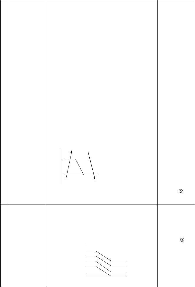
No. |
Item |
|
|
Outline of specifications |
|
|
|
Remarks |
|||||
|
|
|
|
|
|
|
|
|
|
|
|
|
|
6 |
Fan speed control |
(Ceiling type) |
|
|
|
|
|
|
|
|
|
|
|
|
(Continued) |
|
|
|
|
|
|
|
|
|
|
|
Selection of high |
|
|
CODE No. |
Standard |
Type 1 |
Type 3 |
Type 6 |
|||||||
|
|
|
ceiling type |
||||||||||
|
|
|
[5d] |
|
|
|
|
|
|
|
|
|
|
|
|
|
0000 |
0001 |
0002 |
0003 |
|||||||
|
|
|
CODE No.: 5d |
||||||||||
|
|
|
|
|
|
|
|
||||||
|
|
|
SW501 (1)/(2) |
OFF/OFF |
ON/OFF |
OFF/ON |
ON/ON |
||||||
|
|
|
Tap |
HEAT |
COOL |
HEAT |
COOL |
HEAT |
|
COOL |
HEAT |
COOL |
|
|
|
|
F1 |
|
|
|
|
HH |
|
HH |
HH |
HH |
|
|
|
|
F2 |
|
|
HH |
HH |
|
|
|
|
|
|
|
|
|
F3 |
|
|
|
H+ |
H+, H |
|
H+, H |
H+, H |
H+, H |
|
|
|
|
|
|
|
|
|
|
|
|
L+, L |
L+, L |
|
|
|
|
F4 |
|
|
H+ |
|
|
|
|
|
|
|
|
|
|
F5 |
|
HH |
|
H |
|
|
|
|
|
|
|
|
|
F6 |
HH |
|
H |
|
L+ |
|
L+ |
|
|
|
|
|
|
F7 |
H+ |
H+ |
|
|
L |
|
L |
|
|
|
|
|
|
F8 |
|
H |
|
L+ |
|
|
|
|
|
|
|
|
|
|
|
|
|
|
|
|
|
|
|
|
|
|
|
F9 |
H |
|
L+ |
L |
|
|
|
|
|
|
|
|
|
|
|
|
|
|
|
|
|
|
|
|
|
|
|
FA |
|
L+ |
L |
|
|
|
|
|
|
|
|
|
|
|
|
|
|
|
|
|
|
|
|
|
|
|
|
FB |
L+ |
L |
|
|
|
|
|
|
|
|
|
|
|
|
|
|
|
|
|
|
|
|
|
|
|
|
|
FC |
L |
|
|
|
|
|
|
|
|
|
|
|
|
FD |
|
UL |
|
UL |
|
|
UL |
|
UL |
|
|
|
|
|
|
|
|
|
|
|
|
|
|
|
3)In heating operation, the mode changes to [UL] if thermostat is turned off.
4)If Ta ≥ 25°C when heating operation has started and when defrost operation has been cleared, the air conditioner
|
operates with (H) mode or higher mode for |
However only when |
||
|
1 minute after Tc entered in E zone of cool air discharge |
|||
|
the high ceiling |
|||
|
preventive control (No. 7). |
|||
|
selection is set to |
|||
5) |
In automatic cooling/heating operation, the revolution |
|||
[Standard] |
||||
|
frequency of (HH) is set larger than that in the standard |
|
||
|
cooling/heating operation. |
|
||
Ta ˚C |
F5 → F4 |
|
||
|
47 |
However the revolution frequency |
|
|
|
|
|
||
|
|
is restricted in the automatic |
|
|
|
42 |
heating operation as shown in |
|
|
|
the following figure. |
|
||
|
|
F5 |
|
|
6) |
Self-clean operation |
[Self-clean ] is |
||
|
When performing self-clean operation after stopping the |
displayed. |
||
|
cooling operation, the mode becomes 210 rpm. |
|
||
7 |
Cool air discharge |
1) |
In heating operation, the indoor fan is controlled based on |
In D and E zones, |
||
|
preventive control |
|
the detected temperature of Tc sensor or Tcj sensor. As |
the priority is given |
||
|
|
|
shown below, the upper limit of the revolution frequency is |
to air volume |
||
|
|
|
restricted. |
|
|
selection setup of |
|
|
|
However B zone is assumed as C zone for |
remote controller. |
||
|
|
|
|
|||
|
|
|
6 minutes and after when the compressor activated. |
In A zone while |
||
|
|
|
In defrost operation, the control value of Tc is shifted by 6°C. |
thermo is ON, |
||
|
|
|
[PRE-HEAT |
|||
|
|
|
Tc, Tcj |
|
|
|
|
|
|
|
|
(Heating ready)] is |
|
|
|
|
˚C |
HH |
|
displayed. |
|
|
|
32 |
|
||
|
|
|
H |
|
|
|
|
|
|
30 |
|
|
|
|
|
|
L |
E zone |
|
|
|
|
|
|
|
||
|
|
|
28 |
|
|
|
|
|
|
UL |
D zone |
|
|
|
|
|
|
|
||
|
|
|
26 |
|
|
|
|
|
|
|
|
|
|
|
|
|
20 |
OFF |
C zone |
|
|
|
|
|
B zone |
|
|
|
|
|
16 |
|
|
|
|
|
|
|
A zone |
|
|
|
|
|
|
|
|
|
– 30 –
 Loading...