


RAV-SM1603ATZG-E

FILE NO. A07-009
SERVICE MANUAL
AIR-CONDITIONER
SPLIT TYPE
OUTDOOR UNIT <DIGITAL INVERTER>
RAV-SM1603AT-E
RAV-SM1603ATZ-E
RAV-SM1603ATZG-E
INDOOR UNIT <DIGITAL INVERTER>
RAV-SM1403DT-A
RAV-SM1603DT-A
∗ Refer to the Service Manual with File No. A06-010 for Model RAV-SM1403AT-E, and refer to the
Service Manual with File No. A07-003 for Model RAV-SP1403AT-E, respectively.
R410A
PRINTED IN JAPAN, Jun, 2008 ToMo

Adoption of New Refrigerant
This Air Conditioner is a new type which adopts a new refrigerant HFC (R410A) instead of the conventional
refrigerant R22 in order to prevent destruction of the ozone layer.
WARNING
Cleaning of the air filter and other parts of the air filter involves dangerous work in high places, so be sure to
have a service person do it. Do not attempt it yourself.
The cleaning diagram for the air filter is there for the ser vice person, and not for the customer.
CONTENTS
SAFETY CAUTION ............................................................................................ 4
1. SPECIFICATIONS ...................................................................................... 9
1-1. Indoor Unit........................................................................................................... 9
1-2. Outdoor Unit...................................................................................................... 21
1-3. Operation Characteristic Curve....................................................................... 22
2. CONSTRUCTION VIEWS (EXTERNAL VIEWS) ...................................... 23
2-1. Indoor Unit......................................................................................................... 23
2-2. Outdoor Unit...................................................................................................... 24
3. SYSTEMATIC REFRIGERATING CYCLE DIAGRAM.............................. 27
3-1. Indoor Unit......................................................................................................... 27
3-2. Outdoor Unit...................................................................................................... 29
4. WIRING DIAGRAM................................................................................... 30
4-1. Indoor Unit......................................................................................................... 30
4-2. Outdoor Unit...................................................................................................... 32
4-3. Fan Characteristics .......................................................................................... 33
5. SPECIFICATIONS OF ELECTRICAL PARTS .......................................... 34
5-1. Indoor Unit......................................................................................................... 34
5-2. Outdoor Unit...................................................................................................... 34
– 2 –

6. REFRIGERANT R410A............................................................................ 35
6-1. Safety During Installation/Servicing ............................................................... 35
6-2. Refrigerant Piping Installation....................................................................... 35
6-3. Tools .................................................................................................................. 39
6-4. Recharging of Refrigerant................................................................................ 39
6-5. Brazing of Pipes................................................................................................ 40
6-6. Instructions for Re-use Piping of R22 or R407C ............................................ 42
6-7. Tolerance of Pipe Length and Pipe Head........................................................ 46
6-8. Additional Refrigerant Amount........................................................................ 48
6-9. Piping Materials and Sizes............................................................................... 50
6-10. Branch Pipe....................................................................................................... 51
6-11. Distributor ......................................................................................................... 51
7. INDOOR CONTROL CIRCUIT ................................................................. 52
7-1. Indoor Controller Block Diagram..................................................................... 52
7-2. Control Specifications...................................................................................... 53
7-3. Optional Connector Specifications of Indoor P.C. Board.............................. 59
7-4. Indoor Print Circuit Board................................................................................ 60
7-5. Outdoor Print Circuit Board............................................................................. 61
8. CIRCUIT CONFIGURATION AND CONTROL SPECIFICATIONS........... 64
8-1. Outdoor Controls.............................................................................................. 64
9. INDOOR UNIT TROUBLESHOOTING...................................................... 69
9-1. Summary of Troubleshooting........................................................................... 69
9-2. Troubleshooting................................................................................................ 70
10. OUTDOOR UNIT TROUBLESHOOTING.................................................. 83
10-1. Summary of Troubleshooting........................................................................... 83
10-2. Troubleshooting................................................................................................ 85
11. REPLACEMENT OF SERVICE P.C. BOARD ......................................... 112
11-1. Indoort Unit ..................................................................................................... 112
12. SETUP AT LOCAL SITE AND OTHERS................................................ 116
12-1. Indoor Unit....................................................................................................... 116
12-2. Setup at Local Site / Others ........................................................................... 123
12-3. How to Set up Central Control Address Number ......................................... 125
13. ADDRESS SETUP.................................................................................. 127
13-1. Address Setup Procedure.............................................................................. 127
13-2. Address Setup & Group Control.................................................................... 128
13-3. Address Setup (Manual Setting from Remote Controller)........................... 131
14. DETACHMENTS ..................................................................................... 133
14-1. Indoor Unit....................................................................................................... 133
14-2. Outdoor Unit.................................................................................................... 141
15. EXPLODED VIEWS AND PARTS LIST .................................................. 150
15-1. Indoor Unit....................................................................................................... 150
15-2. Outdoor Unit.................................................................................................... 153
– 3 –
SAFETY CAUTION
The important contents concerned to the saf ety are described on the product itself and on this Service Manual.
Please read this Service Manual after understanding the described items thoroughly in the following contents
(Indications/Illustrated marks), and keep them.
[Explanation of indications]
Indication
DANGER
WARNING
CAUTION
∗ Property damage : Enlarged damage concerned to property, furniture, and domestic animal/pet
Indicates contents assumed that an imminent danger causing a death or serious injury of
the repair engineers and the third parties when an incorrect work has been executed.
Indicates possibilities assumed that a danger causing a death or serious injury of the repair
engineers, the third parties, and the users due to troubles of the product after work when
an incorrect work has been executed.
Indicates contents assumed that an injury or proper ty damage (∗) may be caused on the
repair engineers, the third parties, and the users due to troubles of the product after work
when an incorrect work has been executed.
Explanation
[Explanation of illustrated marks]
Mark Explanation
Indicates prohibited items (Forbidden items to do)
The sentences near an illustrated mark describe the concrete prohibited contents.
Indicates mandatory items (Compulsory items to do)
The sentences near an illustrated mark describe the concrete mandatory contents.
Indicates cautions (Including danger/warning)
The sentences or illustration near or in an illustrated mark describe the concrete cautious contents.
[Confirmation of warning label on the main unit]
Confirm that labels are indicated on the specified positions
(Refer to the Parts disassembly diagr am (Outdoor unit).)
If removing the label during parts replace, stick it as the original.
DANGER
Turn “OFF” the breaker before removing the front panel and cabinet, otherwise an electric
shock is caused by high voltage resulted in a death or injury.
During operation, a high voltage with 400V or higher of circuit (∗) at secondary circuit of the
high-voltage transformer is applied.
Turn off breaker.
Execute discharge
between terminals.
Prohibition
If touching a high voltage with the naked hands or body, an electric shock is caused even if using an
electric insulator.
∗ : For details, refer to the electric wiring diagram.
When removing the front panel or cabinet, execute short-circuit and discharge between highvoltage capacitor terminals.
If discharge is not executed, an electric shock is caused by high voltage resulted in a death or injury.
After turning off the breaker, high voltage also keeps to apply to the high-voltage capacitor.
Do not turn on the breaker under condition that the front panel and cabinet are removed.
An electric shock is caused by high voltage resulted in a death or injury.
– 4 –
Check earth wires.
Prohibition of modification.
Use specified parts.
Do not bring a child
close to the equipment.
Insulating measures
No fire
WARNING
Before troubleshooting or repair work, check the earth wire is connected to the earth
terminals of the main unit, otherwise an electric shock is caused when a leak occurs.
If the earth wire is not correctly connected, contact an electric engineer for rework.
Do not modify the products.
Do not also disassemble or modify the parts. It may cause a fire, electric shock or injury.
For spare parts, use those specified (
If unspecified parts are used, a fire or electric shock may be caused.
∗: For details, refer to the parts list.
Before troubleshooting or repair work, do not bring a third party (a child, etc.) except
the repair engineers close to the equipment.
It causes an injury with tools or disassembled parts.
Please inform the users so that the third party (a child, etc.) does not approach the equipment.
Connect the cut-off lead wires with crimp contact, etc, put the closed end side upward
and then apply a water-cut method, otherwise a leak or production of fire is caused at
the users’ side.
When repairing the refrigerating cycle, take the following measures.
1) Be attentive to fire around the cycle. When using a gas stove, etc, be sure to put out fire
before work; otherwise the oil mixed with refrigerant gas may catch fire.
2) Do not use a welder in the closed room.
When using it without ventilation, carbon monoxide poisoning may be caused.
3) Do not bring inflammables close to the refrigerant cycle, otherwise fire of the welder may
catch the inflammables.
∗∗
∗).
∗∗
Refrigerant
Check the used refrigerant name and use tools and materials of the parts which
match with it.
For the products which use R410A refrigerant, the refrigerant name is indicated at a position
on the outdoor unit where is easy to see. To prevent miss-charging, the route of the service
port is changed from one of the former R22.
For an air conditioner which uses R410A, never use other refrigerant than R410A.
For an air conditioner which uses other refrigerant (R22, etc.), never use R410A.
If different types of refrigerant are mixed, abnormal high pressure generates in the
refrigerating cycle and an injury due to breakage may be caused.
Do not charge refrigerant additionally.
If charging refrigerant additionally when refrigerant gas leaks, the refrigerant composition in
the refrigerating cycle changes resulted in change of air conditioner characteristics or
refrigerant over the specified standard amount is charged and an abnormal high pressure is
applied to the inside of the refrigerating cycle resulted in cause of breakage or injury.
Therefore if the refrigerant gas leaks, recover the refrigerant in the air conditioner, execute
vacuuming, and then newly recharge the specified amount of liquid refrigerant.
In this time, never charge the refrigerant over the specified amount.
When recharging the refrigerant in the refrigerating cycle, do not mix the refrigerant
or air other than R410A into the specified refrigerant.
If air or others is mixed with the refrigerant, abnormal high pressure generates in the
refrigerating cycle resulted in cause of injury due to breakage.
After installation work, check the refrigerant gas does not leak.
If the refrigerant gas leaks in the room, poisonous gas generates when gas touches to fire
such as fan heater, stove or cocking stove though the refrigerant gas itself is innocuous.
Never recover the refrigerant into the outdoor unit.
When the equipment is moved or repaired, be sure to recover the refrigerant with recovering
device. The refrigerant cannot be recovered in the outdoor unit; otherwise a serious accident
such as breakage or injury is caused.
Assembly/Cabling
After repair work, surely assemble the disassembled parts, and connect and lead the
removed wires as before. Perform the work so that the cabinet or panel does not
catch the inner wires.
If incorrect assembly or incorrect wire connection was done, a disaster such as a leak or fire
is caused at user’s side.
– 5 –
WARNING
Insulator check
Ventilation
Be attentive to
electric shock
Compulsion
After the work has finished, be sure to use an insulation tester set (500V Megger) to
check the resistance is 2M
metal section (Earth position).
If the resistance value is low, a disaster such as a leak or electric shock is caused at user’s
side.
When the refrigerant gas leaks during work, execute ventilation.
If the refrigerant gas touches to a fire, poisonous gas generates.
A case of leakage of the refrigerant and the closed room full with gas is dangerous because
a shortage of oxygen occurs. Be sure to execute ventilation.
When checking the circuit inevitably under condition of the power-ON, use rubber
gloves and others not to touch to the charging section.
If touching to the charging section, an electric shock may be caused.
When the refrigerant gas leaks, find up the leaked position and repair it surely.
If the leaked position cannot be found up and the repair work is interrupted, pump-down and
tighten the service valve, otherwise the refrigerant gas may leak into the room.
The poisonous gas generates when gas touches to fire such as fan heater, stove or cocking
stove though the refrigerant gas itself is innocuous.
When installing equipment which includes a large amount of charged refrigerant such
as a multi air conditioner in a sub-room, it is necessary that the density does not the
limit even if the refrigerant leaks.
If the refrigerant leaks and exceeds the limit density, an accident of shortage of oxygen is
caused.
For the installation/moving/reinstallation work, follow to the Installation Manual.
If an incorrect installation is done, a trouble of the refrigerating cycle, water leak, electric
shock or fire is caused.
ΩΩ
Ω or more between the charge section and the non-charge
ΩΩ
Check after repair
Check after reinstallation
Put on gloves
Cooling check
After repair work has finished, check there is no trouble.
If check is not executed, a fire, electric shock or injury may be caused.
For a check, turn off the power breaker.
After repair work (installation of front panel and cabinet) has finished, execute a test
run to check there is no generation of smoke or abnormal sound.
If check is not executed, a fire or an electric shock is caused.
Before test run, install the front panel and cabinet.
Check the following items after reinstallation.
1) The earth wire is correctly connected.
2) The power cord is not caught in the product.
3) There is no inclination or unsteadiness and the installation is stable.
If check is not executed, a fire, an electric shock or an injury is caused.
CAUTION
Be sure to put on the gloves (∗) and a long sleeved shirt:
otherwise an injury may be caused with the parts, etc.
(∗) Heavy gloves such as wor k gloves
When the power was turned on, start to work after the equipment has been
sufficiently cooled.
As temperature of the compressor pipes and others became high due to cooling/heating
operation, a burn may be caused.
– 6 –

• New Refrigerant (R410A)
This air conditioner adopts a new HFC type refrigerant (R410A) which does not deplete the ozone layer.
1. Safety Caution Concerned to New Refrigerant
The pressure of R410A is high 1.6 times of that of the former refrigerant (R22).
Accompanied with change of refrigerant, the refrigerating oil has been also changed.
Therefore, be sure that water, dust, the former refrigerant or the former refrigerating oil is not mixed into the
refrigerating cycle of the air conditioner with new refrigerant during installation work or service work.
If an incorrect work or incorrect service is performed, there is a possibility to cause a serious accident.
Use the tools and materials exclusive to R410A to purpose a safe work.
2. Cautions on Installation/Service
1) Do not mix the other refrigerant or refrigerating oil.
For the tools exclusive to R410A, shapes of all the joints including the service port differ from those of
the former refrigerant in order to prevent mixture of them.
2) As the use pressure of the new refrigerant is high, use material thickness of the pipe and tools which are
specified for R410A.
3) In the installation time, use clean pipe materials and work with great attention so that water and others do
not mix in because pipes are affected by impurities such as water, oxide scales, oil, etc.
Use the clean pipes.
Be sure to brazing with flowing nitrogen gas. (Never use gas other than nitrogen gas.)
4) For the earth protection, use a vacuum pump for air purge.
5) R410A refrigerant is azeotropic mixture type refrigerant.
Therefore use liquid type to charge the refrigerant. (If using gas for charging, composition of the
refrigerant changes and then characteristics of the air conditioner change.)
3. Pipe Materials
For the refrigerant pipes, copper pipe and joints are mainly used.
It is necessary to select the most appropriate pipes to conform to the standard.
Use clean material in which impurities adhere inside of pipe or joint to a minimum.
1) Copper pipe
<Piping>
The pipe thickness, flare finishing size, flare nut and others differ according to a refrigerant type.
When using a long copper pipe for R410A, it is recommended to select “Copper or copper-base pipe
without seam” and one with bonded oil amount 40mg/10m or less.
Also do not use crushed, deformed, discolored (especially inside) pipes.
(Impurities cause clogging of expansion valves and capillar y tubes.)
<Flare nut>
Use the flare nuts which are attached to the air conditioner unit.
2) Joint
The flare joint and socket joint are used for joints of the copper pipe.
The joints are rarely used for installation of the air conditioner. However clear impurities when using them.
– 7 –
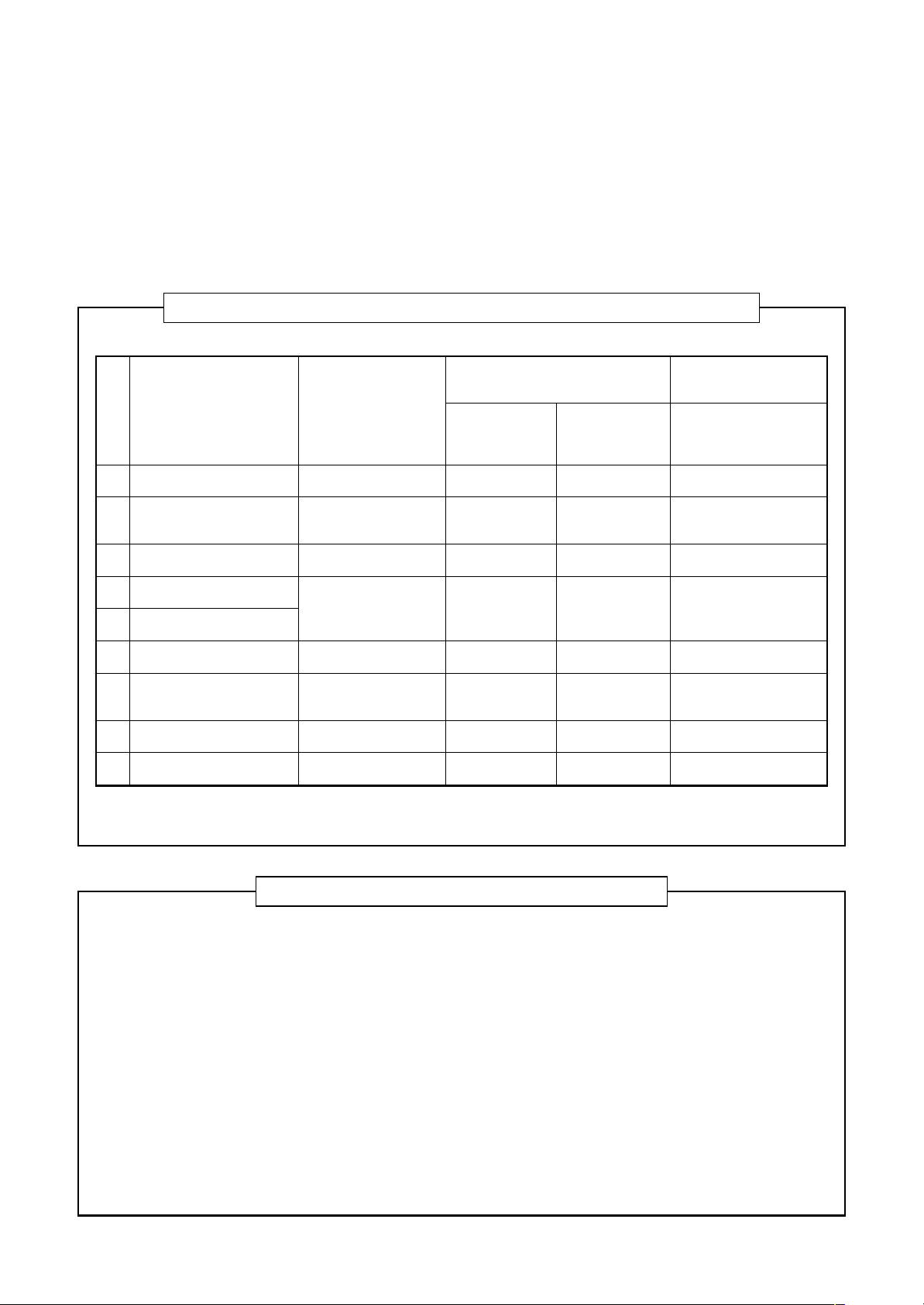
4. Tools
1. Required T ools for R410A
Mixing of different types of oil may cause a trouble such as generation of sludge, clogging of capillary,
etc. Accordingly, the tools to be used are classified into the following three types.
1) Tools exclusive for R410A (Those which cannot be used for conventional refrigerant (R22))
2) Tools exclusive for R410A, but can be also used for conventional refrigerant (R22)
3) Tools commonly used for R410A and for conventional refrigerant (R22)
The table below shows the tools exclusive for R410A and their interchangeability.
Tools exclusive for R410A (The following tools for R410A are required.)
Tools whose specifications are changed for R410A and their interchangeability
No.
Flare tool
Q
Copper pipe gauge for
R
adjusting projection margin
Torque wrench
S
Gauge manifold
T
Charge hose
U
V acuum pump adapter
V
Electronic balance for
W
refrigerant charging
Refrigerant cylinder
X
Leakage detector
Y
Used tool
Usage
Pipe flaring
Flaring by conventional
flare tool
Tightening of flare nut
Evacuating, refrigerant
charge, run check, etc.
Vacuum evacuating
Refrigerant charge
Refrigerant charge
Gas leakage check
air conditioner installation
R410A
Existence of Whether conven-
new equipment tional equipment
for R410A can be used
Ye s *(Note)
Ye s *(Note)
Yes No
Yes No
Yes No
Yes Yes
Yes No
Yes No
Conventional air
conditioner installation
Whether conventional
equipment can be used
Yes
*(Note)
No
No
Yes
Yes
No
Yes
(Note) When flaring is carried out for R410A using the conventional flare tools, adjustment of projection
margin is necessary. For this adjustment, a copper pipe gauge, etc. are necessary.
General tools (Conventional tools can be used.)
In addition to the above exclusive tools, the following equipments which serve also for R22 are necessary
as the general tools.
1) Vacuum pump. Use vacuum pump by
attaching vacuum pump adapter. 7) Screwdriver (+, –)
2) Torque wrench 8) Spanner or Monkey wrench
3) Pipe cutter 9) Hole core drill
4) Reamer 10) Hexagon wrench (Opposite side 4mm)
5) Pipe bender 11) Tape measure
6) Level vial 12) Metal saw
Also prepare the following equipments for other installation method and run check.
1) Clamp meter 3) Insulation resistance tester (Megger)
2) Ther mometer 4) Electroscope
– 8 –
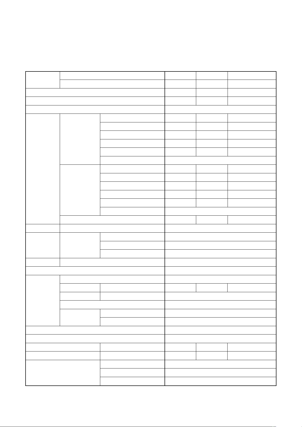
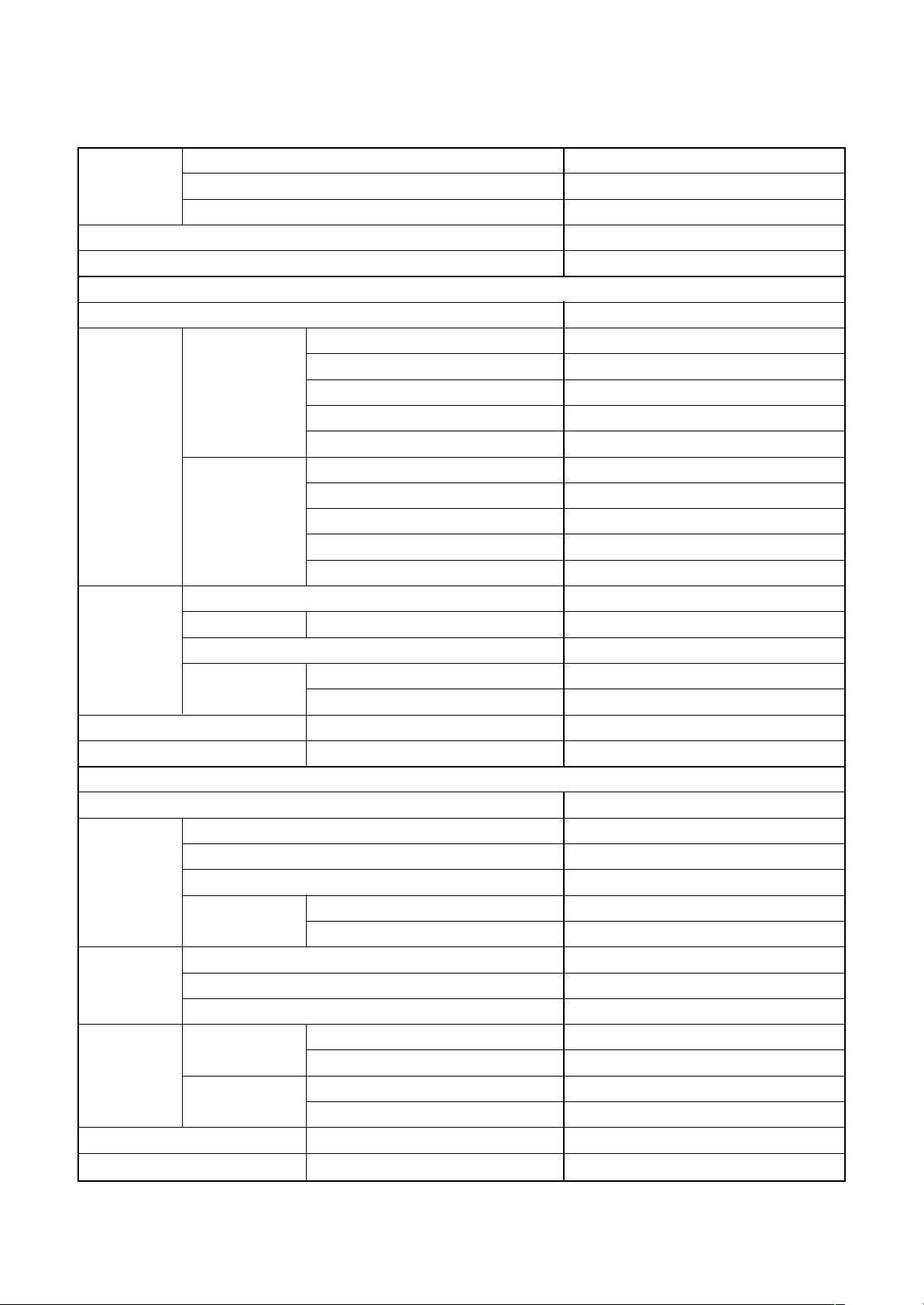
1-1. Indoor Unit
1-1-1. High Static Duct Type
<Single type>
1. SPECIFICATIONS
Model
Cooling capacity (kW)
Heating capacity (kW)
Power supply
Electrical
characteristics
Appearance Main unit
Outer
dimension
Total weight Main unit (kg)
Heat exchanger
Fan unit
Air filter
Controller (sold separately)
Sound pressure level H (dB•A)
Sound power level H (dB•A)
Connecting pipe Liquid side (mm)
Indoor unit RAVOutdoor unit RAV-
Running current (A)
Power consumption (kW)
Cooling
Heating
Maximum current (A)
Main unit Width (mm)
Fan
Standard air flow at 100Pa/HH tap (m³/min.)
Fan speed
Motor (W)
External
static pressure
Power factor (%)
EER
Energy efficiency class ∗
Energy rating ∗∗
Running current (A)
Power consumption (kW)
Power factor (%)
COP
Energy efficiency class ∗
Energy rating ∗∗
Height (mm)
Depth (mm)
Standard (at HH tap) (Pa)
Range at HH tap (Pa)
Gas side (mm)
Drain port (mm)
SM1403DT-A SM1403DT-A SM1603DT-A
SM1403AT-E SP1404AT-E SM1603AT(Z)(ZG)-E
12.5 13.0 14.3
14.0 14.0 16.0
1 phase 240V, 50Hz
21.3 18.5 21.97
4.95 4.32 5.01
96.8 97.3 95
2.53 3.01 2.85
(E) (B) (C)
—
16.9 14.5 20.04
3.94 3.38 4.57
97.1 97.1 95.0
3.55 4.14 3.50
(B) (A) (B)
—
22.8 22.8 32.0
Zinc hot dipping steel plate
380
1050
600
57
Finned tube
Centrifugal fan
55 55 58
2
600
100
50 – 250
None (Arranged locally)
Remote controller
49 49 50
64 64 65
15.9
9.5
32 (VP25)
– 9 –
∗ : IEC standard, ∗∗ : AS standard
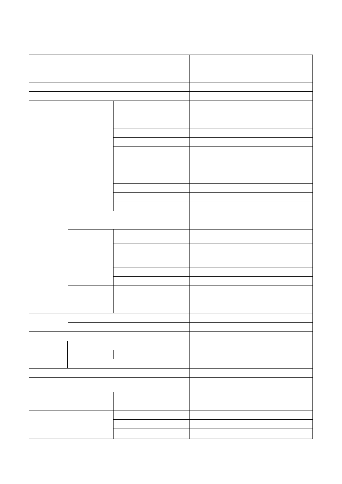
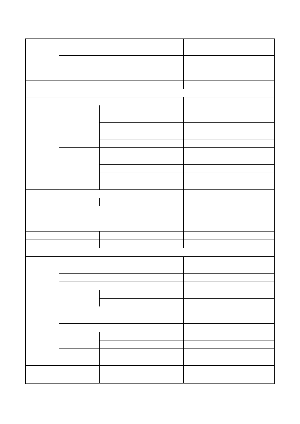
1-1-2. 4-way Air Discharge Cassette Type
<Single type>
Model
Cooling capacity (kW)
Heating capacity (kW)
Power supply
Electrical
characteristics
Appearance
Outer
dimension
Total weight
Heat exchanger
Fan unit Standard air flow H/M/L (m³/min.)
Air filter
Controller (sold separately)
Sound pressure level H/M/L (dB•A)
Sound power level H/M/L (dB•A)
Connecting pipe Liquid side (mm)
Indoor unit RAVOutdoor unit RAV-
Running current (A)
Power consumption (kW)
Cooling
Heating
Maximum current (A)
Main unit
Ceiling panel
(Sold separately)
Main unit Width (mm)
Ceiling panel
(Sold separately)
Main unit (kg)
Ceiling panel (Sold separately) (kg)
Fan
Motor (W)
Power factor (%)
EER
Energy efficiency class ∗
Energy rating ∗∗
Running current (A)
Power consumption (kW)
Power factor (%)
COP
Energy efficiency class ∗
Energy rating ∗∗
Model
Panel color
Height (mm)
Depth (mm)
Height (mm)
Width (mm)
Depth (mm)
Gas side (mm)
Drain port (mm)
SM1604UT-E
SM1603AT(Z)(ZG)-E
14.0
16.0
1 phase 230V (220 – 240V) 50Hz
21.38 – 19.69
4.49
95
3.12
(B)
—
21.20 – 19.43
4.43
95
3.61
(A)
—
29.7
Zinc hot dipping steel plate
RBC-U31PG (W, WS)-E,
RBC-U31PGS (W, WS)-E
W: Moon-white (2.5GY 9.0/0.5),
WS: Stripe-white (2.5GY 9.0/0.5 (Gray: 8B 3/0.3))
319
840
840
30
950
950
24
4.2
Finned tube
Turbo fan
35.5 / 25 / 21
72
Standard filter attached (Long life filter)
RBC-AMT32E, AMS41E,
AS21E2, AX31U (W)-E
45 / 40 / 36
60 / 55 / 51
15.9
9.5
32 (VP25)
– 10 –
∗ : IEC standard, ∗∗ : AS standard
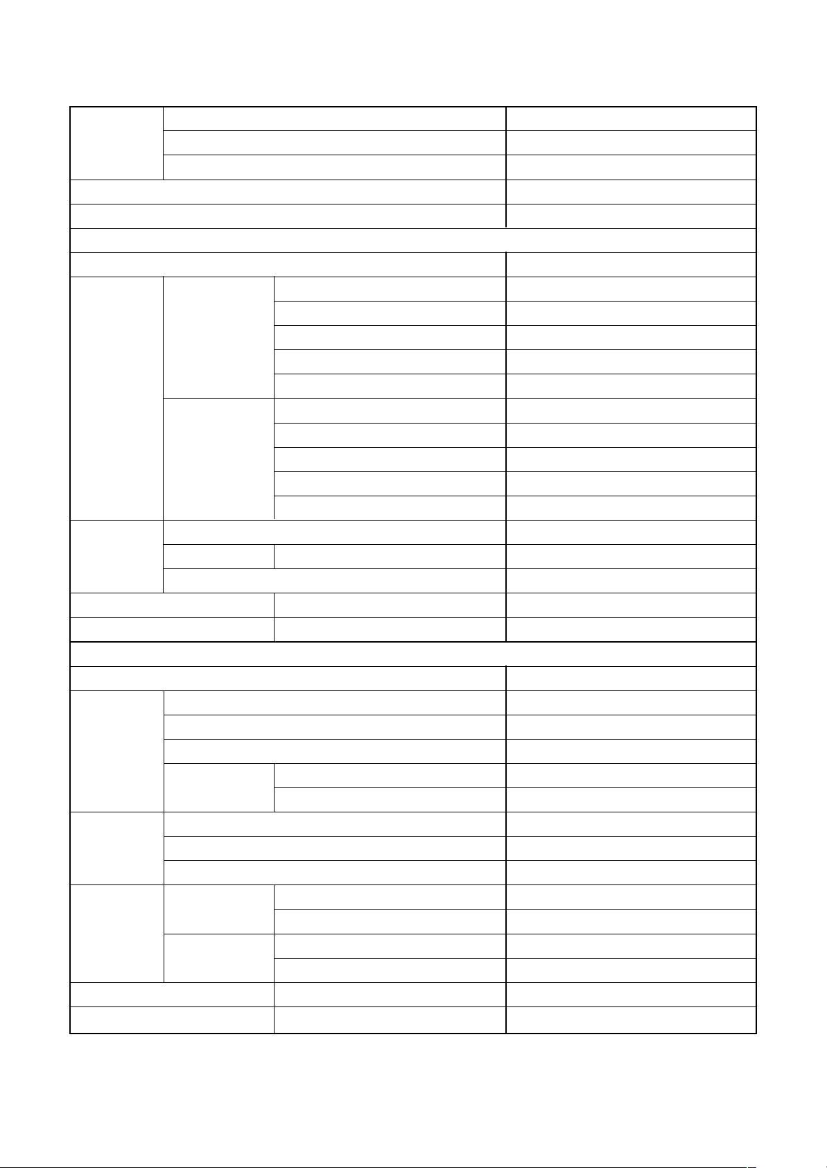
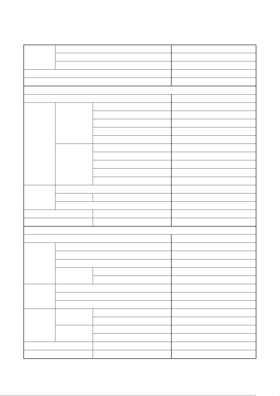
<Twin type>
Indoor unit 1 RAV- SM804UT-E
Model Indoor unit 2 RAV- SM804UT-E
Outdoor unit RAV- SM1603AT(Z)(ZG)-E
Cooling capacity (kW) 14.0
Heating capacity (kW) 16.0
Indoor unit
Power supply 1 phase 230V (220 – 240V) 50Hz
Running current (A) 21.48 – 19.69
Power consumption (kW) 4.49
Cooling Power factor (%) 95
EER 3.12
Electrical
characteristics
Heating Power factor (%) 95
Fan Turbo fan
Fan unit Standard air flow H/M/L (m³/min.) 20.5 / 16.0 / 13.5
Motor (W) 20
Sound pressure level H/M/L (dB•A) 35 / 31 / 28
Sound power level H/M/L (dB•A) 50 / 46 / 43
Power supply 1 phase 230V (220 – 240V) 50Hz
Standard length (m) 7.5
Min. length (m) 5
Refrigerant
pipe
Max. total length (m) 50
Height
difference
Energy efficiency class ∗ (B)
Running current (A) 21.20 – 19.43
Power consumption (kW) 4.43
COP 3.61
Energy efficiency class ∗ (A)
Outdoor unit
Outdoor lower (m) 30
Outdoor higher (m) 30
Fan Propeller fan
Fan unit Standard air flow volume (m³/min.) 103
Motor (W) 100 + 100
Gas side
Connecting
pipe
Liquid side
Sound pressure level Cooling/Heating (dB•A) 51 / 53
Sound power level Cooling/Heating (dB•A) 68 / 70
Main (mm) 15.9
Sub (mm) 15.9
Main (mm) 9.5
Sub (mm) 9.5
– 11 –
∗ : IEC standard
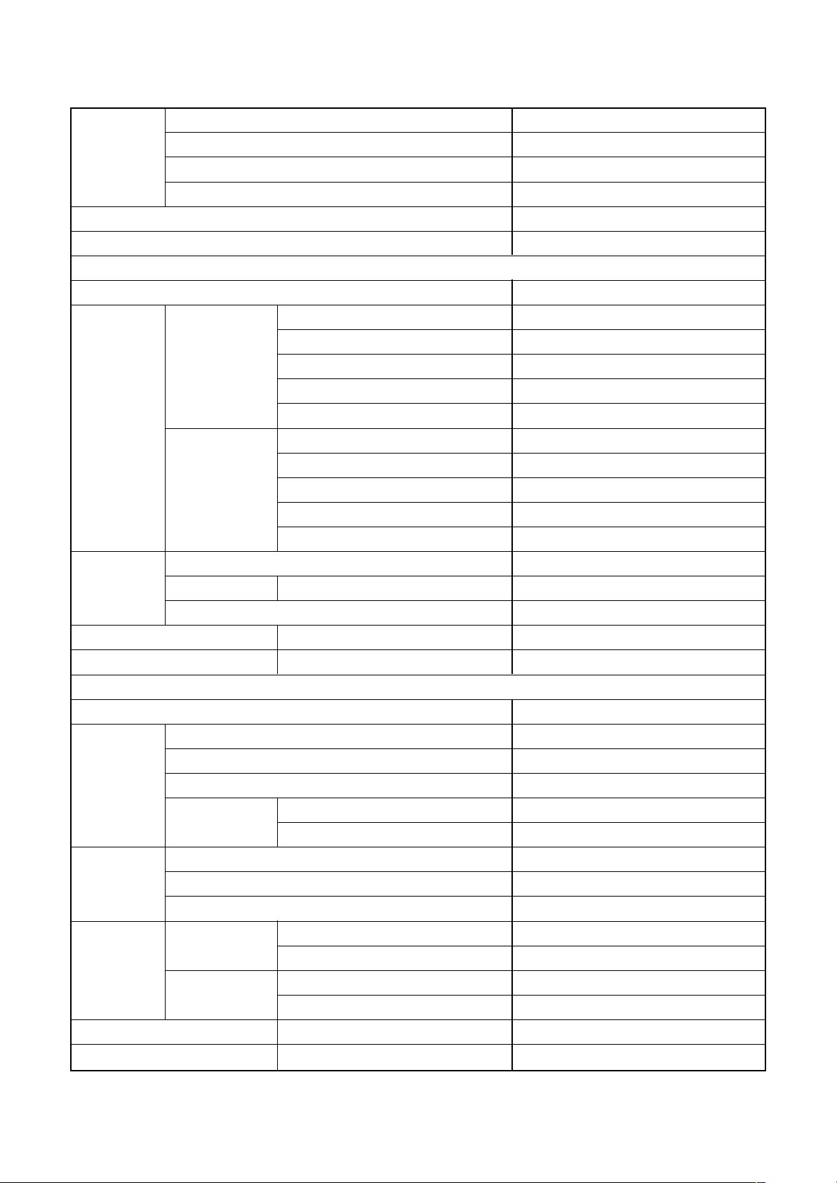
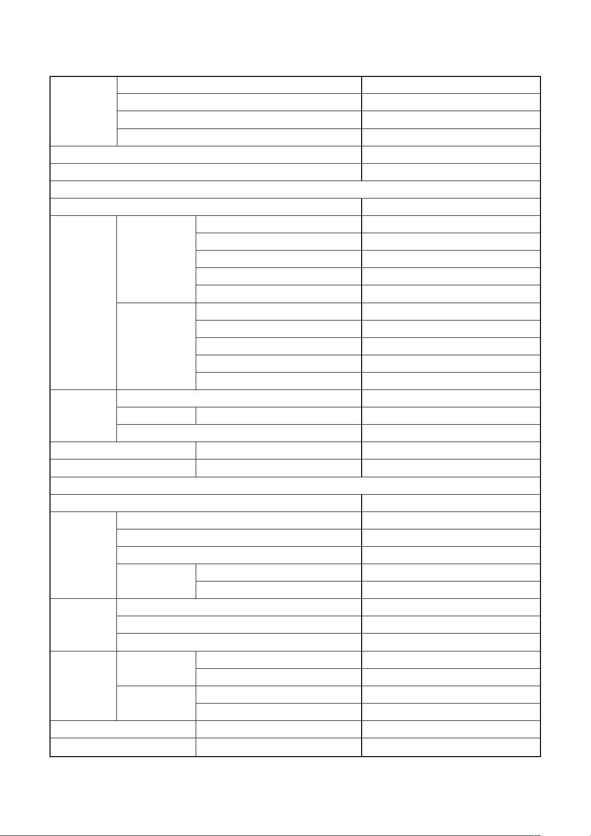
<Triple type>
Indoor unit 1 RAV- SM564UT-E
Model
Cooling capacity (kW) 14.0
Heating capacity (kW) 16.0
Power supply 1 phase 230V (220 – 240V) 50Hz
Electrical
characteristics
Indoor unit 2 RAV- SM564UT-E
Indoor unit 3 RAV- SM564UT-E
Outdoor unit RAV- SM1603AT(Z)(ZG)-E
Indoor unit
Running current (A) 21.48 – 19.69
Power consumption (kW) 4.49
Cooling Power factor (%) 95
EER 3.12
Energy efficiency class ∗ (B)
Running current (A) 21.20 – 19.43
Power consumption (kW) 4.43
Heating Power factor (%) 95
COP 3.61
Energy efficiency class ∗ (A)
Fan Turbo fan
Fan unit Standard air flow H/M/L (m³/min.) 17.5 / 14.5 / 13.0
Motor (W) 14
Sound pressure level H/M/L (dB•A) 32 / 29 / 28
Sound power level H/M/L (dB•A) 47 / 44 / 43
Outdoor unit
Power supply 1 phase 230V (220 – 240V) 50Hz
Standard length (m) 7.5
Min. length (m) 5
Refrigerant
pipe
Fan unit Standard air flow volume (m³/min.) 103
Connecting
pipe
Max. total length (m) 50
Height
difference
Fan Propeller fan
Motor (W) 100 + 100
Gas side
Liquid side
Outdoor lower (m) 30
Outdoor higher (m) 30
Main (mm) 15.9
Sub (mm) 12.7
Main (mm) 9.5
Sub (mm) 6.4
Sound pressure level Cooling/Heating (dB•A) 51 / 53
Sound power level Cooling/Heating (dB•A) 68 / 70
– 12 –
∗ : IEC standard
1-1-3. Concealed Duct Type
<Twin type>
Indoor unit 1 RAV- SM802BT-E
Model Indoor unit 2 RAV- SM802BT-E
Outdoor unit RAV- SM1603AT(Z)(ZG)-E
Cooling capacity (kW) 14.0
Heating capacity (kW) 16.0
Indoor unit
Power supply 1 phase 230V (220 – 240V) 50Hz
Running current (A) 24.50 – 22.46
Power consumption (kW) 5.12
Cooling Power factor (%) 95
EER 2.73
Electrical
characteristics
Heating Power factor (%) 95
Fan Centrifugal fan
Standard air flow H/M/L (m³/min.) 19.0 / 16.2 / 13.3
Fan unit Motor (W) 120
External
static pressure
Sound pressure level H/M/L (dB•A) 40 / 37 / 34
Sound power level H/M/L (dB•A) 55 / 52 / 49
Power supply 1 phase 230V (220 – 240V) 50Hz
Standard length (m) 7.5
Min. length (m) 5
Refrigerant
pipe
Fan unit Standard air flow volume (m³/min.) 103
Connecting
pipe
Sound pressure level Cooling/Heating (dB•A) 51 / 53
Sound power level Cooling/Heating (dB•A) 68 / 70
Max. total length (m) 50
Height
difference
Fan Propeller fan
Motor (W) 100 + 100
Gas side
Liquid side
Energy efficiency class ∗ —
Running current (A) 22.44 – 20.57
Power consumption (kW) 4.69
COP 3.41
Energy efficiency class ∗ —
Standard (at shipment) (Pa) 40
Set up for tap exchange (Pa) 20 / 40 / 70 / 100
Outdoor unit
Outdoor lower (m) 30
Outdoor higher (m) 30
Main (mm) 15.9
Sub (mm) 15.9
Main (mm) 9.5
Sub (mm) 9.5
– 13 –
∗ : IEC standard
<Triple type>
Indoor unit 1 RAV- SM562BT-E
Model
Cooling capacity (kW) 14.0
Heating capacity (kW) 16.0
Power supply 1 phase 230V (220 – 240V) 50Hz
Electrical
characteristics
Fan unit Motor (W) 120
Sound pressure level H/M/L (dB•A) 40 / 37 / 33
Sound power level H/M/L (dB•A) 55 / 52 / 48
Power supply 1 phase 230V (220 – 240V) 50Hz
Refrigerant
pipe
Fan unit Standard air flow volume (m³/min.) 103
Connecting
pipe
Sound pressure level Cooling/Heating (dB•A) 51 / 53
Sound power level Cooling/Heating (dB•A) 68 / 70
Indoor unit 2 RAV- SM562BT-E
Indoor unit 3 RAV- SM562BT-E
Outdoor unit RAV- SM1603AT(Z)(ZG)-E
Indoor unit
Running current (A) 24.50 – 22.46
Power consumption (kW) 5.12
Cooling Power factor (%) 95
EER 2.73
Energy efficiency class ∗ —
Running current (A) 22.44 – 20.57
Power consumption (kW) 4.69
Heating Power factor (%) 95
COP 3.41
Energy efficiency class ∗ —
Fan Centrifugal fan
Standard air flow H/M/L (m³/min.) 13.0 / 11.9 / 9.8
External static pressure (Factory setting) (Pa) 40
External static pressure (Pa) 20 / 40 / 70 / 100
Outdoor unit
Standard length (m) 7.5
Min. length (m) 5
Max. total length (m) 50
Height
difference
Fan Propeller fan
Motor (W) 100 + 100
Gas side
Liquid side
Outdoor lower (m) 30
Outdoor higher (m) 30
Main (mm) 15.9
Sub (mm) 12.7
Main (mm) 9.5
Sub (mm) 6.4
– 14 –
∗ : IEC standard
1-1-4. Under Ceiling Type
<Twin type>
Indoor unit 1 RAV- SM802CT-E
Model Indoor unit 2 RAV- SM802CT-E
Outdoor unit RAV- SM1603AT(Z)(ZG)-E
Cooling capacity (kW) 14.0
Heating capacity (kW) 16.0
Indoor unit
Power supply 1 phase 230V (220 – 240V) 50Hz
Running current (A) 23.88 – 21.89
Power consumption (kW) 4.99
Cooling Power factor (%) 95
EER 2.81
Electrical
characteristics
Heating Power factor (%) 95
Fan Centrifugal fan
Fan unit Standard air flow H/M/L (m³/min.) 18.5 / 16.7 / 14.6
Motor (W) 60
Sound pressure level H/M/L (dB•A) 38 / 36 / 33
Sound power level H/M/L (dB•A) 53 / 51 / 48
Power supply 1 phase 230V (220 – 240V) 50Hz
Standard length (m) 7.5
Min. length (m) 5
Refrigerant
pipe
Max. total length (m) 50
Height
difference
Energy efficiency class ∗ —
Running current (A) 22.44 – 20.57
Power consumption (kW) 4.69
COP 3.41
Energy efficiency class ∗ —
Outdoor unit
Outdoor lower (m) 30
Outdoor higher (m) 30
Fan Propeller fan
Fan unit Standard air flow volume (m³/min.) 103
Motor (W) 100 + 100
Gas side
Connecting
pipe
Liquid side
Sound pressure level Cooling/Heating (dB•A) 51 / 53
Sound power level Cooling/Heating (dB•A) 68 / 70
Main (mm) 15.9
Sub (mm) 15.9
Main (mm) 9.5
Sub (mm) 9.5
– 15 –
∗ : IEC standard

<Triple type>
Indoor unit 1 RAV- SM562CT-E
Model
Cooling capacity (kW) 14.0
Heating capacity (kW) 16.0
Power supply 1 phase 230V (220 – 240V) 50Hz
Electrical
characteristics
Indoor unit 2 RAV- SM562CT-E
Indoor unit 3 RAV- SM562CT-E
Outdoor unit RAV- SM1603AT(Z)(ZG)-E
Indoor unit
Running current (A) 23.88 – 21.89
Power consumption (kW) 4.99
Cooling Power factor (%) 95
EER 2.81
Energy efficiency class ∗ —
Running current (A) 22.44 – 20.57
Power consumption (kW) 4.69
Heating Power factor (%) 95
COP 3.41
Energy efficiency class ∗ —
Fan Centrifugal fan
Fan unit Standard air flow H/M/L (m³/min.) 13.0 / 11.2 / 10.0
Motor (W) 60
Sound pressure level H/M/L (dB•A) 36 / 33 / 30
Sound power level H/M/L (dB•A) 51 / 48 / 45
Outdoor unit
Power supply 1 phase 230V (220 – 240V) 50Hz
Standard length (m) 7.5
Min. length (m) 5
Refrigerant
pipe
Fan unit Standard air flow volume (m³/min.) 103
Connecting
pipe
Max. total length (m) 50
Height
difference
Fan Propeller fan
Motor (W) 100 + 100
Gas side
Liquid side
Outdoor lower (m) 30
Outdoor higher (m) 30
Main (mm) 15.9
Sub (mm) 12.7
Main (mm) 9.5
Sub (mm) 6.4
Sound pressure level Cooling/Heating (dB•A) 51 / 53
Sound power level Cooling/Heating (dB•A) 68 / 70
– 16 –
∗ : IEC standard

1-1-5. High Wall T ype
<Twin type>
Indoor unit 1 RAV- SM802KRT-E
Model Indoor unit 2 RAV- SM802KRT-E
Outdoor unit RAV- SM1603AT(Z)(ZG)-E
Cooling capacity (kW) 14.0
Heating capacity (kW) 16.0
Indoor unit
Power supply 1 phase 230V (220 – 240V) 50Hz
Running current (A) 24.40 – 22.37
Power consumption (kW) 5.10
Cooling Power factor (%) 95
EER 2.75
Electrical
characteristics
Heating Power factor (%) 95
Fan Cross flow fan
Fan unit Standard air flow H/M/L (m³/min.) 18.5 / 14.6 / 12.2
Motor (W) 30
Sound pressure level H/M/L (dB•A) 45 / 41 / 36
Sound power level H/M/L (dB•A) 60 / 56 / 51
Power supply 1 phase 230V (220 – 240V) 50Hz
Standard length (m) 7.5
Min. length (m) 5
Refrigerant
pipe
Max. total length (m) 50
Height
difference
Energy efficiency class ∗ —
Running current (A) 23.83 – 21.84
Power consumption (kW) 4.98
COP 3.21
Energy efficiency class ∗ —
Outdoor unit
Outdoor lower (m) 30
Outdoor higher (m) 30
Fan Propeller fan
Fan unit Standard air flow volume (m³/min.) 103
Motor (W) 100 + 100
Gas side
Connecting
pipe
Liquid side
Sound pressure level Cooling/Heating (dB•A) 51 / 53
Sound power level Cooling/Heating (dB•A) 68 / 70
Main (mm) 15.9
Sub (mm) 15.9
Main (mm) 9.5
Sub (mm) 9.5
– 17 –
∗ : IEC standard
<Triple type>
Indoor unit 1 RAV- SM562KRT-E
Model
Cooling capacity (kW) 14.0
Heating capacity (kW) 16.0
Power supply 1 phase 230V (220 – 240V) 50Hz
Electrical
characteristics
Indoor unit 2 RAV- SM562KRT-E
Indoor unit 3 RAV- SM562KRT-E
Outdoor unit RAV- SM1603AT(Z)(ZG)-E
Indoor unit
Running current (A) 24.40 – 22.37
Power consumption (kW) 5.10
Cooling Power factor (%) 95
EER 2.75
Energy efficiency class ∗ —
Running current (A) 23.83 – 21.84
Power consumption (kW) 4.98
Heating Power factor (%) 95
COP 3.21
Energy efficiency class ∗ —
Fan Cross flow fan
Fan unit Standard air flow H/M/L (m³/min.) 14.0 / 12.5 / 10.7
Motor (W) 30
Sound pressure level H/M/L (dB•A) 39 / 36 / 33
Sound power level H/M/L (dB•A) 54 / 51 / 48
Outdoor unit
Power supply 1 phase 230V (220 – 240V) 50Hz
Standard length (m) 7.5
Min. length (m) 5
Refrigerant
pipe
Fan unit Standard air flow volume (m³/min.) 103
Connecting
pipe
Max. total length (m) 50
Height
difference
Fan Propeller fan
Motor (W) 100 + 100
Gas side
Liquid side
Outdoor lower (m) 30
Outdoor higher (m) 30
Main (mm) 15.9
Sub (mm) 12.7
Main (mm) 9.5
Sub (mm) 6.4
Sound pressure level Cooling/Heating (dB•A) 51 / 53
Sound power level Cooling/Heating (dB•A) 68 / 70
– 18 –
∗ : IEC standard
1-1-6. Compact 4-way Cassette (600 × 600) Type
<Triple type>
Indoor unit 1 RAV- SM562MUT-E
Model
Cooling capacity (kW) 14.0
Heating capacity (kW) 16.0
Power supply 1 phase 230V (220 – 240V) 50Hz
Electrical
characteristics
Indoor unit 2 RAV- SM562MUT-E
Indoor unit 3 RAV- SM562MUT-E
Outdoor unit RAV- SM1603AT(Z)(ZG)-E
Indoor unit
Running current (A) 23.88 – 21.89
Power consumption (kW) 4.99
Cooling Power factor (%) 95
EER 2.81
Energy efficiency class ∗ —
Running current (A) 22.44 – 20.57
Power consumption (kW) 4.69
Heating Power factor (%) 95
COP 3.41
Energy efficiency class ∗ —
Fan Turbo fan
Fan unit Standard air flow H/M/L (m³/min.) 13.3 / 11.2 / 9.1
Motor (W) 60
Sound pressure level H/M/L (dB•A) 43 / 39 / 34
Sound power level H/M/L (dB•A) 58 / 54 / 49
Outdoor unit
Power supply 1 phase 230V (220 – 240V) 50Hz
Standard length (m) 7.5
Min. length (m) 5
Refrigerant
pipe
Fan unit Standard air flow volume (m³/min.) 103
Connecting
pipe
Max. total length (m) 50
Height
difference
Fan Propeller fan
Motor (W) 100 + 100
Gas side
Liquid side
Outdoor lower (m) 30
Outdoor higher (m) 30
Main (mm) 15.9
Sub (mm) 12.7
Main (mm) 9.5
Sub (mm) 6.4
Sound pressure level Cooling/Heating (dB•A) 51 / 53
Sound power level Cooling/Heating (dB•A) 68 / 70
– 19 –
∗ : IEC standard
1-1-7. Slim Duct Type
<Triple type>
Indoor unit 1 RAV- SM564SDT-E
Model
Cooling capacity (kW) 14.0
Heating capacity (kW) 16.0
Power supply 1 phase 230V (220 – 240V) 50Hz
Electrical
characteristics
Fan unit Motor (W) 60
Sound
pressure level
Sound
power level
Power supply 1 phase 230V (220 – 240V) 50Hz
Refrigerant
pipe
Fan unit Standard air flow volume (m³/min.) 103
Connecting
pipe
Sound pressure level Cooling/Heating (dB•A) 51 / 53
Sound power level Cooling/Heating (dB•A) 68 / 70
Indoor unit 2 RAV- SM564SDT-E
Indoor unit 3 RAV- SM564SDT-E
Outdoor unit RAV- SM1603AT(Z)(ZG)-E
Indoor unit
Running current (A) 23.88 – 21.89
Power consumption (kW) 4.99
Cooling Power factor (%) 95
EER 2.81
Energy efficiency class ∗ —
Running current (A) 22.44 – 20.57
Power consumption (kW) 4.69
Heating Power factor (%) 95
COP 3.41
Energy efficiency class ∗ —
Fan Centrifugal fan
Standard air flow H/M/L (m³/min.) 13.0 / 11.3 / 9.7
External
static pressure
Under air inlet H/M/L (dB•A) 45 / 40 / 36
Back air inlet H/M/L (dB•A) 33 / 31 / 28
Under air inlet H/M/L (dB•A) 60 / 55 / 51
Back air inlet H/M/L (dB•A) 48 / 46 / 43
Standard length (m) 7.5
Min. length (m) 5
Max. total length (m) 50
Height
difference
Fan Propeller fan
Motor (W) 100 + 100
Gas side
Liquid side
Standard (at shipment) (Pa) 10
Set up for tap exchange (Pa) 10 / 20 / 35 / 50
Outdoor unit
Outdoor lower (m) 30
Outdoor higher (m) 30
Main (mm) 15.9
Sub (mm) 12.7
Main (mm) 9.5
Sub (mm) 6.4
– 20 –
∗ : IEC standard
1-2. Outdoor Unit
Model name
Power supply
Type
Compressor Motor (kW)
Pole
Refrigerant charged (kg)
Refrigerant control
Standard length (m)
Min. length (m)
Inter
connecting pipe
Max. total length (m)
Additional refrigerant charge
under long piping connector
Height
difference
Height (mm)
Outdoor lower (m)
Outdoor higher (m)
RAV-SM1603AT(Z)(ZG)-E
1 phase 230V (220 – 240V) 50Hz
Hermetic compressor
3.75
4
3.1
Pulse motor valve
7.5
5
50
40g/m
(31m to 50m)
30
30
1340
Outer dimension Width (mm)
Depth (mm)
Appearance
Total weight (kg)
Heat exchanger
Fan
Fan unit Standard air flow (m³/h)
Motor (W)
Gas side (mm)
Connecting pipe
Liquid side (mm)
Sound pressure level Cooling/Heating (dB•A)
Sound power level Cooling/Heating (dB•A)
Outside air temperature, Cooling (°C)
Outside air temperature, Heating (°C)
900
320
Silky shade (Muncel 1Y8.5/0.5)
99
Finned tube
Propeller fan
103
100 + 100
15.9
9.5
51 / 53
68 / 70
43 to –15
15 to –15
– 21 –
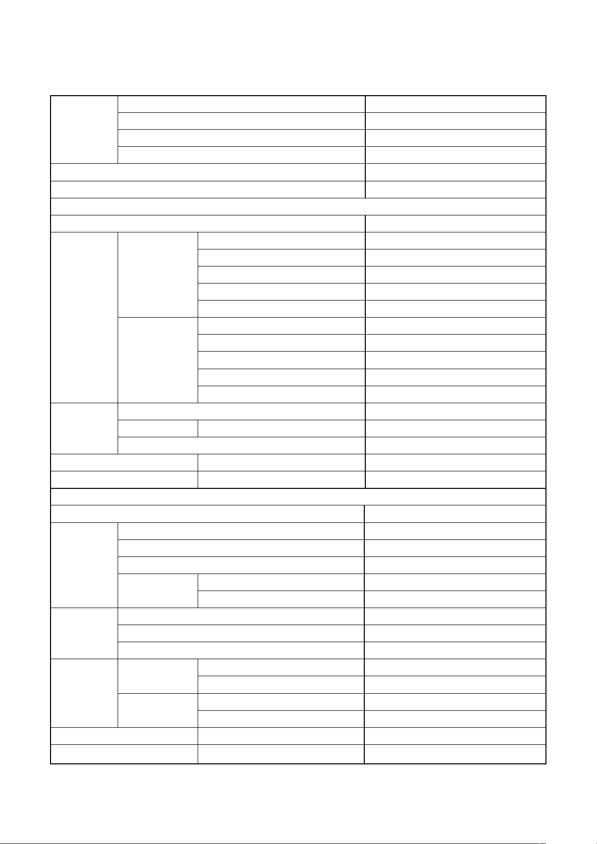
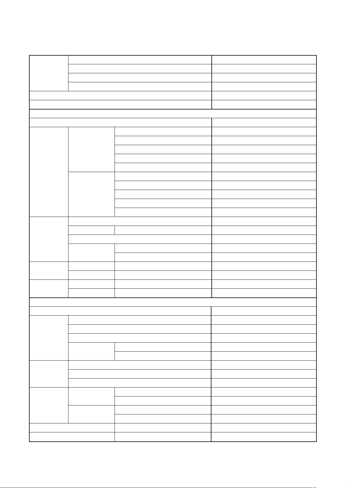
1-3. Operation Characteristic Curve
• Operation characteristic curve
RAV-SM1603A T-E, RAV -SM1603ATZ-E, RAV-SM1603ATZG-E
<Cooling> <Heating>
25
23.7
22
20
18
16
14
12
Current (A)
10
8
6
4
2
0
0 204060
Compressor speed (rps)
• Conditions
Indoor : DB27°C/WB19°C
Outdoor : DB35°C
Air flow : High
Pipe length : 7.5m
230V
79 100 120
28.2
26
24
22
20
18
16
14
12
10
8
6
4
2
30
28.2
26
24
22
20
18
16
14
Current (A)
12
10
8
6
4
2
0
0 204060
Compressor speed (rps)
• Conditions
Indoor : DB20°C
Outdoor : DB7°C/WB6°C
Air flow : High
Pipe length : 7.5m
230V
78.6 100 120
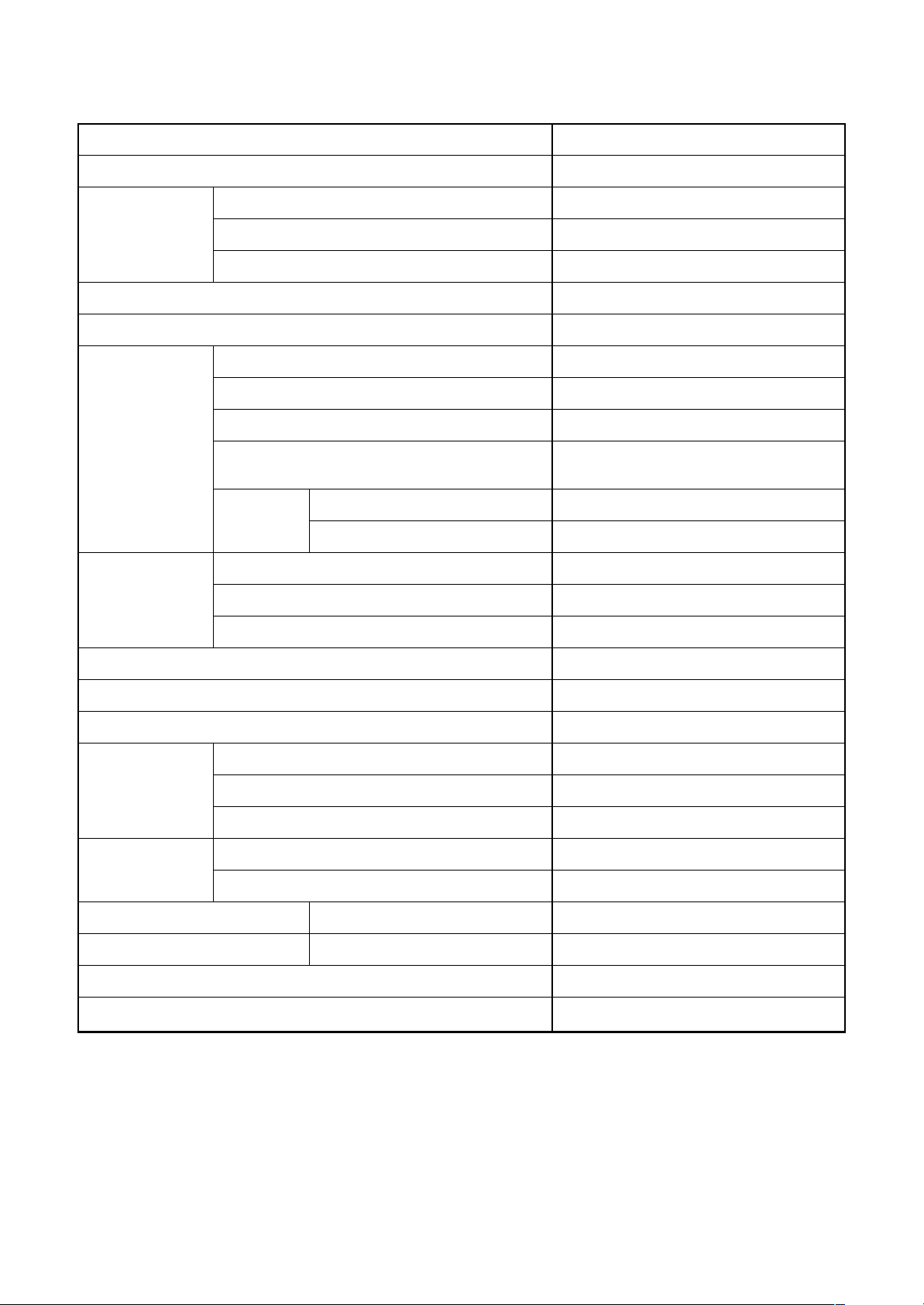
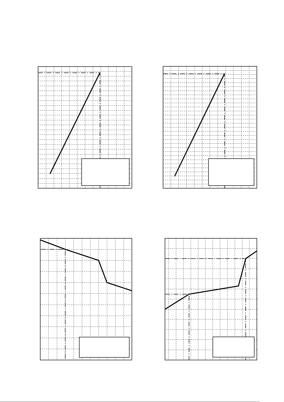
• Capacity variation ratio according to temperature
RAV-SM1603A T-E, RAV -SM1603ATZ-E, RAV-SM1603ATZG-E
<Cooling> <Heating>
105
100
95
90
85
80
75
70
Capacity ratio (%)
65
60
55
50
32 33 34 35 36 37 38 39
• Conditions
Indoor : DB27°C/WB19°C
Indoor air flow : High
Pipe length : 7.5m
40
41 42 43
120
110
100
90
80
70
60
50
Capacity ratio (%)
40
30
20
10
0
-14-12-10-8-6-4-20246810
• Conditions
Indoor : DB20°C
Indoor air flow : High
Pipe length : 7.5m
Outdoor temp. (°C)
Outdoor temp. (°C)
– 22 –
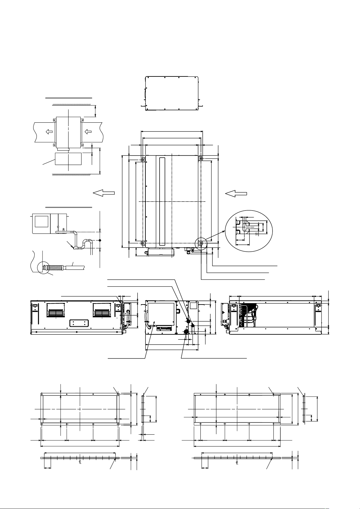
2. CONSTRUCTION VIEWS (EXTERNAL VIEWS)
2-1. Indoor Unit
RAV-SM1403DT-A, RAV-SM1603DT-A
Service work space
200
or more
704
664
600(52) (52)
Check port
400 × 800
Plug
(Port for check
and clean)
200
Drain trap
Drain pipe
Adhesive inhibited
3-M5 hole for drain pump kit
1300 or more
Air flow Air flow
1050
(900)(95)
950 (Bolt pitch) (50)(50)
100
or more
50
or more
Refrigerant piping (3/8” (Ø9.52))
Refrigerant piping (5/8” (Ø15.88))
25
145145 20
25
490
600
Electric parts box Drain port (Outer diameter: Ø32)
(915)
(36)
(53)
(72)
Refrigerant piping (5/8” (Ø15.88))
Refrigerant piping (3/8” (Ø9.52))
Drain port (Outer diameter: Ø32)
380
97 50 42
(30)
48
Hung-up plate
965 (Bolt pitch) (35)(50)
(111) 854 (85)
12
30
50
32
52
271 (28)81
Flange (Air outlet side) Flange (Air inlet side)
20
276
(Inside)
25 25
12
20
256 256271
65 65
757 (Inside)
807
11 × 65 = 715
24-Ø5 hole
(Include in the other side)
8-Ø7 hole
10-Ø5 hole
(Include in the other side)
10296
316
4 × 60 = 240
60
15
10
12 25 67.5 250 250
15
25
– 23 –
10-Ø5 hole
(Include in the other side)8-Ø7 hole
274
(Inside)
20 20
25 25
845 (Inside)
885
11 × 65 = 715
24-Ø5 hole
(Include in the other side)
250 67.5
300
15
324
25
4 × 60 = 240
60
365 17.5
17.5
Drain hole (Ø28 × 88)
128
118
74
Air inlet port
380
200 60
Air inlet
port
75
Air outlet
port
383
150 600
46
70
Drain hole (Ø25)
34
170
A legs
B legs
48
39
96
Mounting bolt hole
(Ø12 × 17 long hole)
54
40
40
Details of A legs Details of B legs
12
Name Note
Refrigerant piping hole
1
Indoor/Outdoor unit
connecting wire inlet hole
2
Power supply inlet hole Ø38 Kockout hole
Mounting bolt hole
(Ø12 × 17 U-shape hole)
——
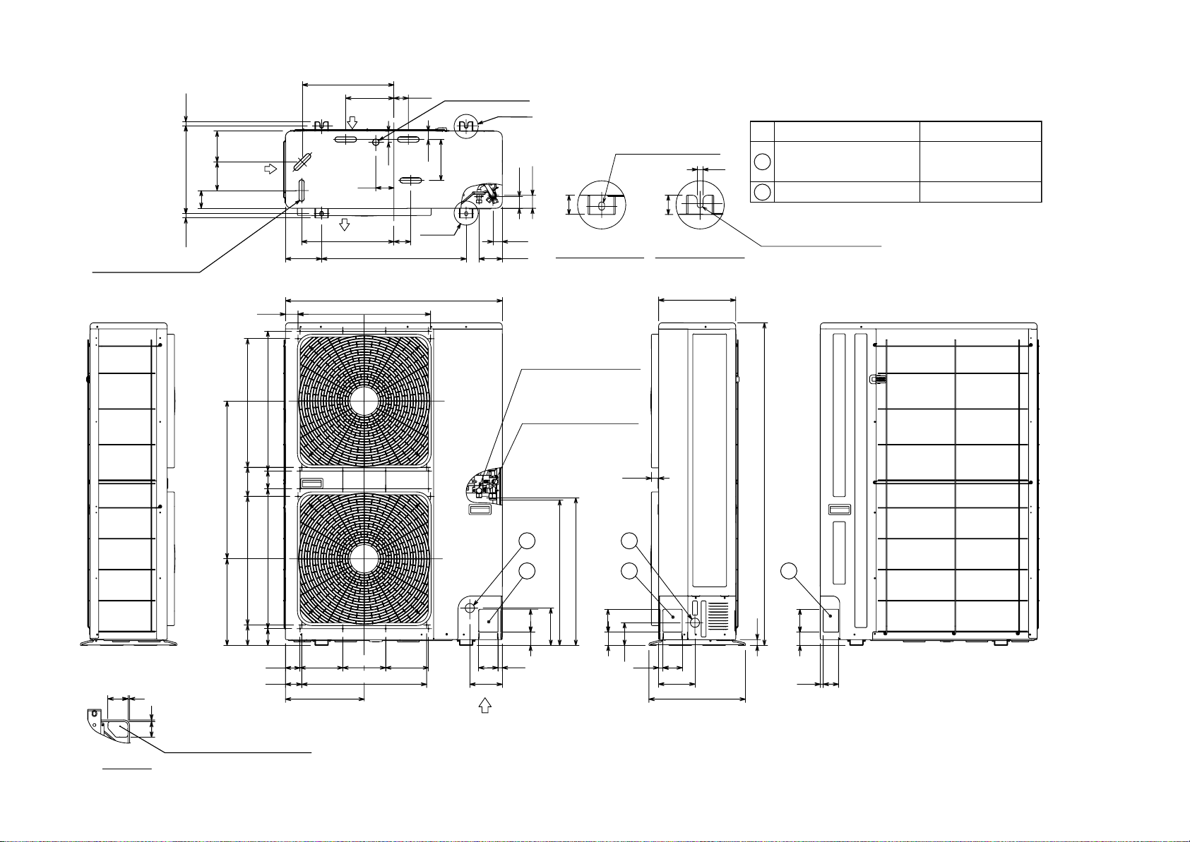
2-2. Outdoor Unit
RAV-SM1603A T-E, RAV -SM1603ATZ-E, RAV-SM1603ATZG-E
52
– 24 –
121 53453485
655
360
70 74581 581
60
68 518 135 151 12
83 7
178
327 400
900
550
Refrigerant pipe
connecting port
(Ø9.5 flare at liquid side)
Refrigerant pipe
connecting port
(Ø15.9 flare at gas side)
30
2
1
605
613
155
55 95
178 178 80 18 8018
2
1 1
95
55
94
320
1340
24
55 95
64
Z views
65 7
Knockout for downward piping
Z
Unit : mm
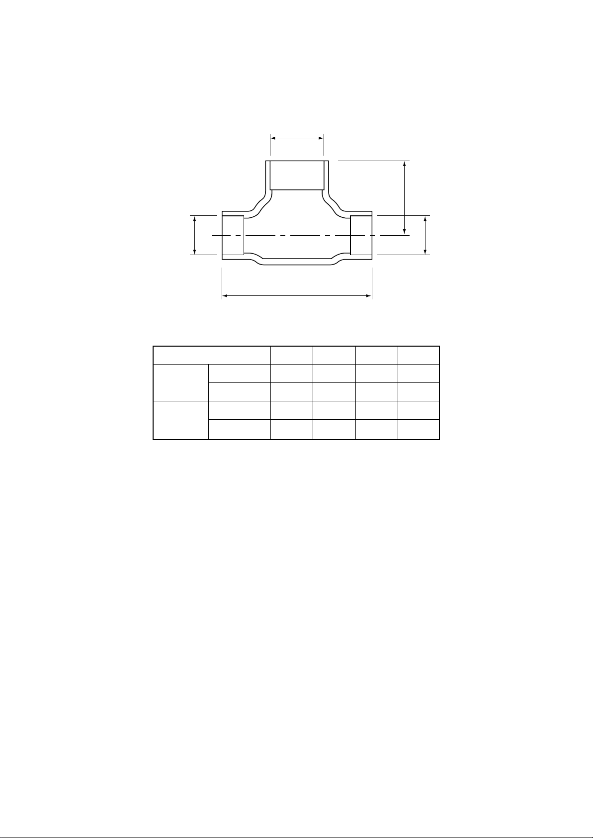
RBC-TWP30E2, RBC-TWP50E2 (Simultaneous Twin)
Inner diameter Ø C
B
Inner
diameter Ø D
Model (RBC-)
TWP30E2
TWP50E2
Liquid side
Gas side
Liquid side
Gas side
Inner
diameter Ø D
A
ABCD
36 14 Ø9.5 Ø6.4
43 23 Ø15.9 Ø12.7
34 14 Ø9.5 Ø9.5
44 21 Ø15.9 Ø15.9
– 25 –
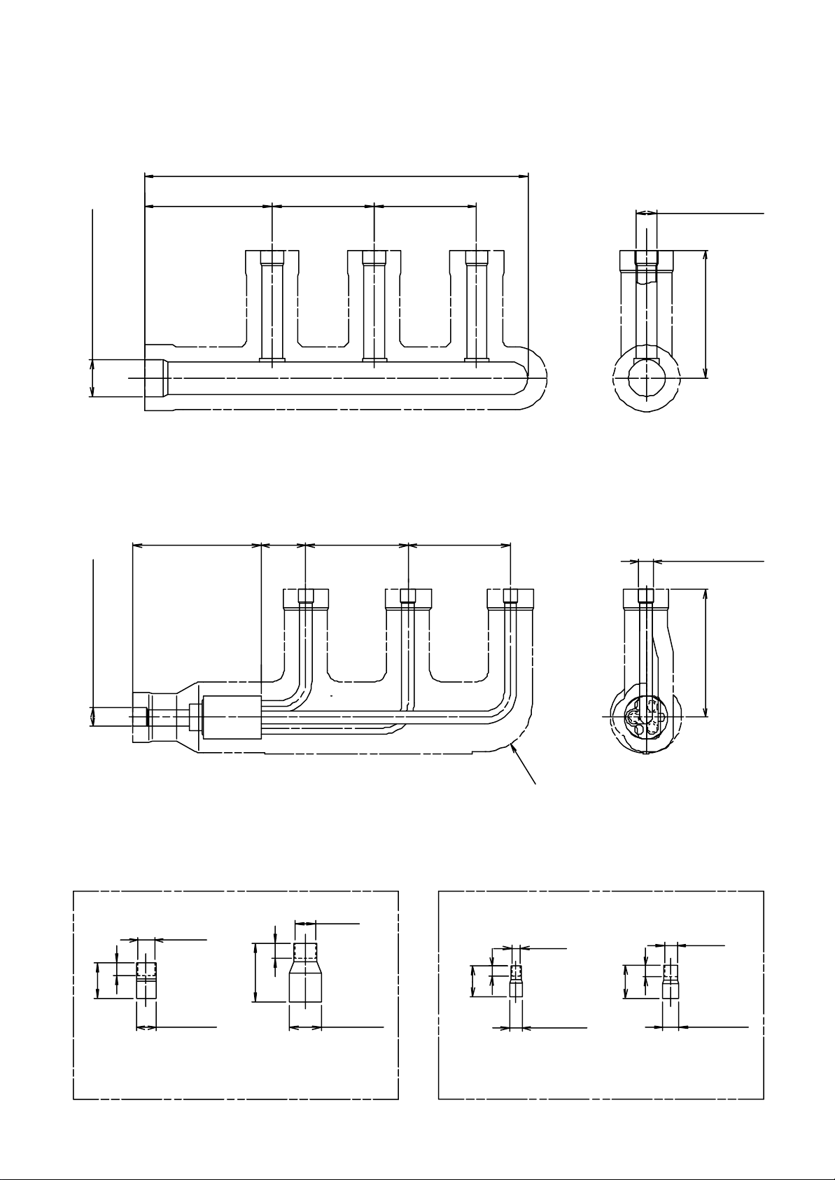
RBC-TRP100E (Simultaneous Triple)
<Gas side>
Header assembly
300
Inner diameter Ø25.4Inner diameter Ø12.7
<Liquid side>
Branch pipe assembly
35
80 80100
Inner diameter
Ø15.9
100
80 80100
Inner diameter
Ø9.52
Insulator
Gas side socket Liquid side socket
Ø15.9
28
10
Ø12.7
Ø15.9
(External
diameter)
46
12
6
24
Ø25.4
(External
diameter)
Ø6.4
Ø9.5
(External
diameter)
100
Ø9.5
9
26
Ø12.7
(External
diameter)
3 pcs. 3 pcs.1 pc. 1 pc.
– 26 –
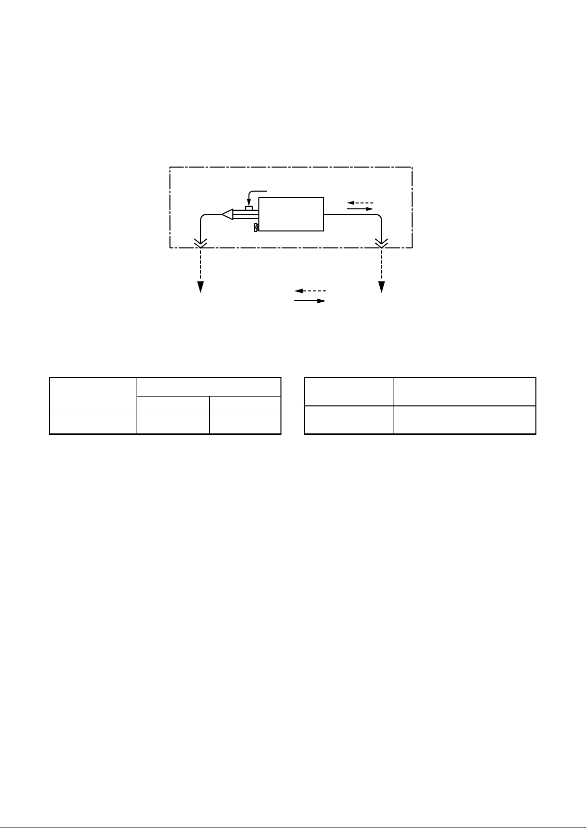
3. SYSTEMATIC REFRIGERATING CYCLE DIAGRAM
3-1. Indoor Unit
<Indoor unit to be connected to RAV-SM1403DT-A, RAV-SM1603DT-A>
• Single type (Combination of one indoor unit and one outdoor unit)
Distributor
(Strainer
incorporated)
TC sensor
Refrigerant pipe
at liquid side ØB
Indoor unit
TCJ sensor
Air heat
exchanger
Heating
Cooling
Refrigerant pipe
at gas side ØA
To outdoor unitTo outdoor unit
Dimension table Capillary tube specifications
Indoor unit
SM140, 160 type
Outer diameter of refrigerant pipe
Gas side ØA Liquid side ØB
15.9 9.5
Model
RAV-SM∗∗∗DT
SM140, 160 type
Inner dia. × Length × Q’ty
Ø2 × 200 × 3, Ø2 × 300 × 1
Ø2 × 350 × 2, Ø2 × 400 × 1
– 27 –
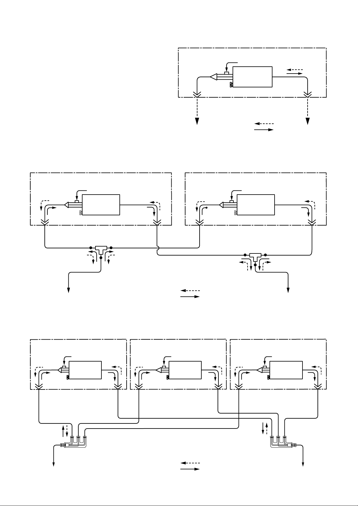
<Indoor unit to be connected to RAV-SM1603AT-E, RAV-SM1603ATZ-E, RAV-SM1603ATZG-E>
• Single type
(Combination of one indoor unit and
one outdoor unit)
Distributor
(Strainer
incorporated)
TC sensor
Refrigerant pipe
at liquid side
Outer diameter Ø9.5
Heating
Cooling
• Twin type (Combination of two indoor units and one outdoor unit)
Distributor
(Strainer
incorporated)
TC sensor
Indoor A unit
TCJ sensor
Air heat
exchanger
Distributor
(Strainer
incorporated)
TC sensor
Indoor unit
TCJ sensor
Air heat
exchanger
Refrigerant pipe
at gas side
Outer diameter Ø15.9
To outdoor unitTo outdoor unit
Indoor B unit
TCJ sensor
Air heat
exchanger
Refrigerant pipe
at liquid side
Outer diameter Ø6.4
Branch pipe
Refrigerant pipeat liquid side
Outer diameter Ø9.5
To outdoor unit
Refrigerant pipe
at gas side
Outer diameter Ø12.7
Refrigerant pipe
at liquid side
Outer diameter Ø6.4
Refrigerant pipeat gas side
Outer diameter Ø15.9
Heating
Cooling
• Triple type (Combination of three indoor units and one outdoor unit)
Distributor
(Strainer
incorporated)
TC sensor
Refrigerant pipe
at liquid side
Outer diameter
Ø6.4
Indoor A unit
TCJ sensor
Air heat
exchanger
Refrigerant pipe
at gas side
Outer diameter
Ø12.7
Distributor
(Strainer
incorporated)
TC sensor
Refrigerant pipe
at liquid side
Outer diameter
Ø6.4
Indoor B unit
TCJ sensor
Air heat
exchanger
Refrigerant pipe
at gas side
Outer diameter
Ø12.7
Distributor
(Strainer
incorporated)
TC sensor
Refrigerant pipe
at liquid side
Outer diameter
Ø6.4
Refrigerant pipe
at gas side
Outer diameter Ø12.7
Branch pipe
To outdoor unit
Indoor C unit
TCJ sensor
Air heat
exchanger
Refrigerant pipe
at gas side
Outer diameter
Ø12.7
Refrigerant
pipeat liquid side
Outer diameter Ø9.5
To outdoor unit
Distributor
Heating
Cooling
– 28 –
Distributor
Refrigerant
pipeat gas side
Outer diameter Ø15.9
To outdoor unit
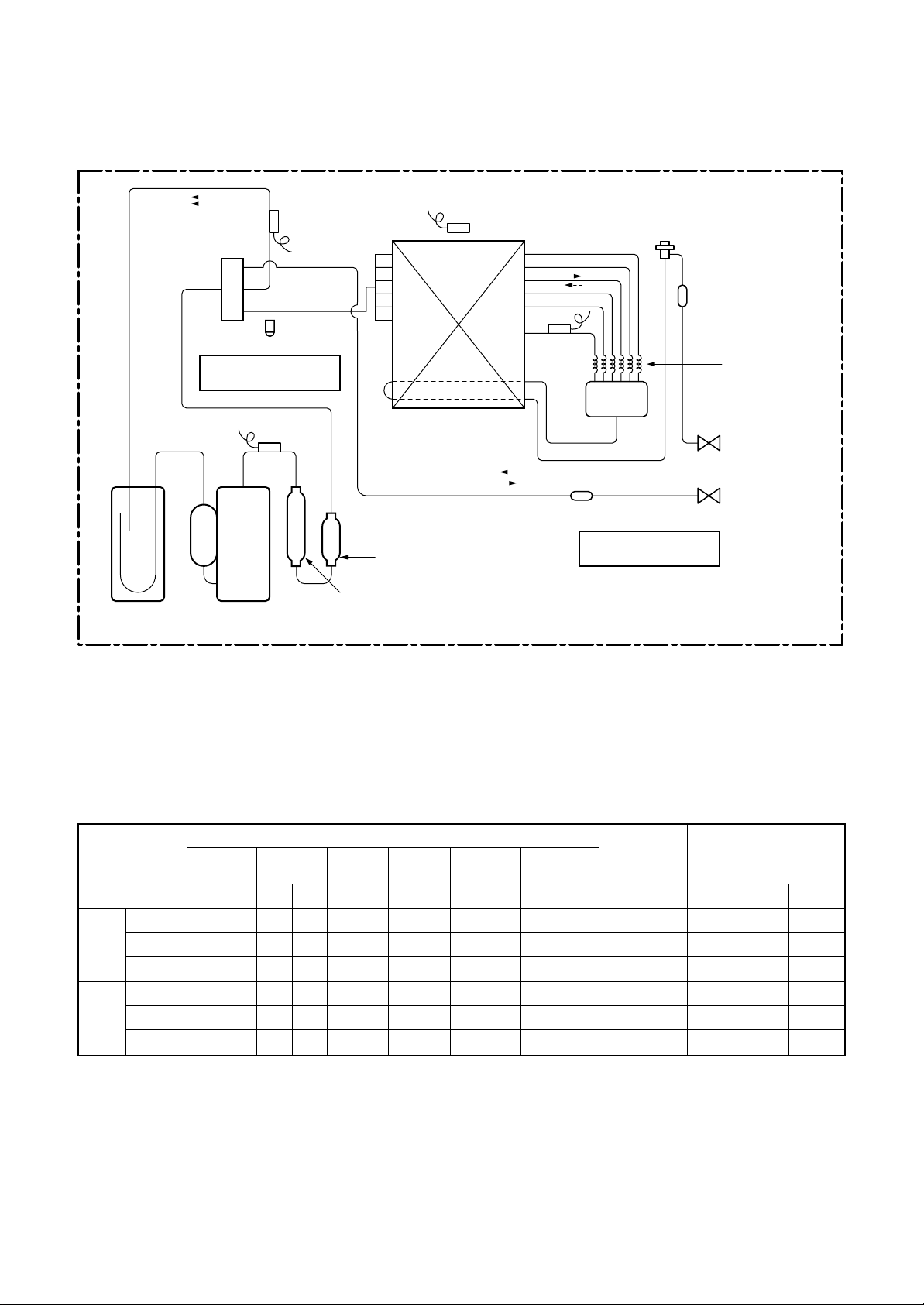
3-2. Outdoor Unit
Muffler
RAV-SM1603A T-E, RAV -SM1603ATZ-E, RAV-SM1603ATZG-E
Accumulator
(2500cc)
TS sensor
Check joint
Cooling: High pressure
Heating: Low pressure
TD sensor
Rotary compressor
(DA422A3F-25M)
Muffler
Muffler
Ø25 × L210
TO sensor
Heat exchanger
Ø8, 2 rows, 52 stages
FP1.45, flat fin
In cooling operation
In heating operation
Ø25 × L180
TE sensor
Distributor
Strainer
PMV
Strainer
Capillary
Ø4 ×Ø3 (6 pcs.)
Refrigerant pipe
at liquid side Ø9.5
Packed valve
Refrigerant pipe
at gas side Ø15.9
Ball valve
Cooling: Low pressure
Heating: High pressure
Systematic Diagram of Refrigerating Cycle
* This compressor has 4-pole motor.
The value when compressor frequency (Hz) is measured by a clamp meter becomes 2 times of No. of
compressor revolutions (rps).
Standard
Cooling Overload
Low load
Standard
Heating Overload
Low load
Pressure
(MPa) (kg/cm²g)
Pd Ps Pd Ps
2.85 0.83 29.1 8.5
3.41 1.04 34.8 10.6
2.08 0.54 21.2 5.5
2.82 0.66 28.7 6.7
2.44 1.13 24.9 11.5
2.32 0.25 23.7 2.5
Discharge Suction
Pipe surface temperature (°C)
Indoor heat Outdoor heat
exchanger exchanger
(TD) (TS) (TC) (TE)
80 11 9 39
84 14 15 49
54 5 8 37
83 3 46 2
82 18 55 15
88 –20 38 –16
Compressor
drive revolution
frequency
(rps)
65
56
30
62
32
84
Indoor
fan
HIGH
HIGH
LOW
HIGH
LOW
HIGH
Indoor/Outdoor
temp. conditions
Indoor Outdoor
27/19 35/–
32/24 43/–
18/15.5 –15/–
(DB/WB) (°C)
20/– 7/6
30/– 24/18
15/––15/–
– 29 –
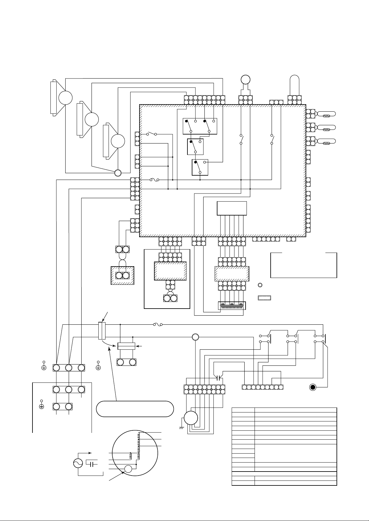
4-1. Indoor Unit
RAV-SM1403DT-A, RAV-SM1603DT-A
4. WIRING DIAGRAM
Earth
screw
Earth
screw
Power supply
220–240V~, 50Hz
Outdoor unit
8
Relay
43F3
7
Noise absorber
RED WHI BLK
1 2
1 2 3
WHIRED
Serial
L N
signal
8
Relay
43F2
7
Noise absorber
8
Relay
43F1
7
Noise absorber
WHIWHIWHI
1
BLKBLK
A B
A B
Wired
remote controller
3P Connector (RED)
(At the time of shipment)
RED
WHI
RED
BRW
RED WHI
L N
3
Earth
screw
RC
Overheating protection switch
Power supply
220–240V~, 50Hz
(Only use twin setting)
For twin setting,
please reconnect this 3P connector
to the R-S terminal 3P connector.
Internal wiring part of fan motor
BLK
WHI
GRY
RED
49F
YEL
BLU
ORN
WHI
CN083 (WHI)
1
3
1
3
1 1
3 3
5 5
1
2
1
2
313
Fuse (T10A, 250V~)
RY004
CN034 (GRY)
CN309
(YEL)
Fuse
(T5A, 250V~)
CN067
(BLK)
CN066
(WHI)
CN041
(BLU)
CN51
(RED)
3P Connector (RED)
(At the time of twin setting)
CN050
1 2 3 4 5
1 2 3 4 5
1 2
P.C. board
for TCC-LINK
(MCC-1440)
CN40
(BLU)
U3 U4
Relay terminal
Option
YEL
BLU
ORN
Fan
(WHI)
(Normal)
99775 331
RY007
3 4 5
1 2
1 2
BRW BRW
BRW
WHI
1 3 4 5 6 9
1 3 4 5 6 7 9
WHI
1
HMLUL
RY006 RY002 RY001
RY005
Power supply
circuit
CN074
(WHI)
3
113
CN01
(WHI)
TR
WHI
1 2 3 4 5 6
BLK
WHI
1 2 3 4 5 6
1 2 3 4 5 6
P.C. board
(MCC-1520)
1 2 3 4 5 6
1 2 3 4 5 6
BRW
2
RC
GRY
(WHI)
(WHI)
YEL
BLK
BLU
RED
ORN
GRY
FM
DP
DP
CN033
CN068
(GRN)
(BLU)
113 1 3 1 2 3
P.C. board
(MCC-1403)
CN075
(WHI)
6
RED
RED
ORN
ORN
CN02
(YEL)
RED
ORN
WHI
RED
YEL
WHI
1 3 4 5 7 9
(High satatic pressure)
Symbol
FM
RC
TR
TA
TC, TCJ
49F
RY002
RY005
RY006
RY007
43F1, 2, 3
Fuse
Fuse
CS
DP
CN061
(YEL)
1 2 3 4 5 61 2 3 4 51 2 3 4 5
1. indicates the terminal board and
the number indicates the terminal number.
2. The dashed line indicates wiring at the local site.
3. indicates P.C. board.
4. When install Drain Pump. please connect
Float Switch Connector to Connector CN030.
5. When changing external static pressure,
please reconnect Fan Motor connecter (WHI)
to high static pressure connector (RED).
65
Relay
43F3
43
YEL
GRY
Fan motor
Running capacitor
Power transformer
Indoor temp. sensor
Indoor heat exchanger sensor
Overheating protection switch (OFF: 135°C)
Relay for drain pump motor
Relay for fan motor
T10A, 250V~
T5A, 250V~ (On P.C. board (MCC-1403))
Optional parts
Float switch
Drain pump motor
WHI
1 33
CN104
(YEL)
CN102
(RED)
CN101
(BLK)
CN080
(GRN)
CN073
(RED)
CN070
(WHI)
CN060
(WHI)
CN032
(WHI)
1 2
(Fan drive)
Color Identification
RED : RED
WHI : WHITE
BLK : BLACK
YEL : YELLOW
BLU : BLUE
65
Relay
43
BLU
BLU
(RED)
Parts name
CS
CN030
(RED)
121
2
TCJ
121
2
121
2
1
2
3
Outside
( )
error input
1
(EXCT)
2
1
(Filter)
2
6
5
4
Option
3
2
1
GRY : GRAY
ORN : ORANGE
BRW : BROWN
GRN : GREEN
REDRED
65
43F2
3
4
ORN
BLK
Closed-end
connector
TA
TC
Relay
43F1
BLK
– 30 –
 Loading...