


 Loading...
SERVICE MANUAL
REVERSING AUTOMATIC DOCUMENT FEEDER
MR-3018/3020/3021/3022
Model: MR-3018/3020/3021/3022
Publish Date: June 2005
File No. SME050006H0
R05032183100-TTEC
Ver08_2011-12

Trademarks
•The official name of Windows XP is Microsoft Windows XP Operating System.
•The official name of Windows 7 is Microsoft Windows 7 Operating System.
•Microsoft, Windows, Windows NT, Windows Vista and the brand names and product names of other Microsoft products are trademarks or registered trademarks of Microsoft Corporation in the U.S. and/or other countries.
•Molykote is a registered trademark of Dow Corning Corporation.
•FLOIL is a registered trademark of Kanto Kasei Ltd. CORPORATION.
•Other company names and product names in this manual are the trademarks of their respective companies.
© 2005 - 2011 TOSHIBA TEC CORPORATION All rights reserved
Under the copyright laws, this manual cannot be reproduced in any form without prior written permission of TOSHIBA TEC CORPORATION.
11/12
General Precautions for Installation/Servicing/Maintenance for the MR-3018/3020/3021/3022
The installation and service shall be done by a qualified service technician.
1)When installing the MR-3018/3020/3021/3022 to the Equipment, be sure to follow the instructions described in the “Unpacking/Set-Up Procedure for the MR-3018/3020/3021/3022” booklet which comes with each unit of the MR-3018/3020/3021/3022.
2)The MR-3018/3020/3021/3022 should be installed by an authorized/qualified person.
3)The equipment must be grounded for safety.
4)Before starting installation, servicing or maintenance work, be sure to turn OFF and unplug the equipment first.
5)The equipment shall be installed near the socket outlet and shall be easily accessible.
6)Be sure to fix and plug in the power cable securely after the installation so that no one trips over it.
7)Unplug the power cable and clean the area around the prongs of the plug and socket outlet once a year or more. A fire may occur when dust lies on this area.
8)The MR-3018/3020/3021/3022 should be grounded to the specified positions on the machine frame.
9)When servicing or maintaining the MR-3018/3020/3021/3022, be careful about the rotating or operation sections such as gears, pulleys, sprockets, cams, belts, etc.
10)Reassembly of disassembled parts is the reverse of the disassembly unless otherwise noted in this manual or other related documents.
Care should be taken that small parts, such as screws, washers, pins, E-rings, star washers, harnesses are not installed in the wrong places.
11)Basically, the machine should not be operated with any parts removed or disassembled.
12)Delicate parts for preventing safety hazard problems (such as switches, sensors, etc. if any) should be handled/installed/adjusted correctly.
13)Use suitable measuring instruments and tools.
14)During servicing or maintenance work, be sure to check the serial No. plate and other cautionary labels (if any) to see if they are clean and firmly fixed. If not, take appropriate actions.
15)The PC board must be stored in an anti-electrostatic bag and handled carefully using a wristband, because the ICs on it may be damaged due to static electricity. Before using the wrist band, pull out the power cord plug of the equipment and make sure that there is no uninsulated charged objects in the vicinity.
16)For the recovery and disposal of used MR-3018/3020/3021/3022, consumable parts and packing materials, follow the relevant local regulations/rules should be followed.
17)After completing installation, servicing and maintenance of the MR-3018/3020/3021/3022, return the MR-3018/3020/3021/3022 to its original state, and check operation.
11/12
|
|
CONTENTS |
|
1. |
SPECIFICATIONS......................................................................................................... |
1-1 |
|
2. |
GENERAL DESCRIPTION............................................................................................ |
2-1 |
|
|
2.1 |
Main Components................................................................................................................ |
2-1 |
|
2.2 |
Sectional View ..................................................................................................................... |
2-2 |
|
2.3 |
Electric Parts Layout............................................................................................................ |
2-3 |
|
2.4 |
Symbols and Functions of Various Components................................................................. |
2-4 |
|
2.5 |
Diagram of Signal Blocks..................................................................................................... |
2-5 |
|
2.6 |
Description of Interface Signals........................................................................................... |
2-6 |
3. |
DESCRIPTION OF OPERATIONS ............................................................................... |
3-1 |
|
|
3.1 |
DRIVE SYSTEM .................................................................................................................. |
3-1 |
|
|
3.1.1 Outline ...................................................................................................................... |
3-1 |
|
|
3.1.2 Original feed motor drive section.............................................................................. |
3-2 |
|
|
3.1.3 Read motor drive section ......................................................................................... |
3-3 |
|
|
3.1.4 Original exit/reverse motor drive section .................................................................. |
3-4 |
|
3.2 |
Original Size Detection ........................................................................................................ |
3-5 |
|
|
3.2.1 Outline ...................................................................................................................... |
3-5 |
|
|
3.2.2 Original tray width sensor......................................................................................... |
3-5 |
|
|
3.2.3 Original width detection sensors-1 and -2 / Original length detection sensor........... |
3-6 |
|
3.3 |
FLOW CHART..................................................................................................................... |
3-8 |
|
3.4 |
DESCRIPTION OF CIRCUIT............................................................................................. |
3-16 |
|
|
3.4.1 Drive Circuit for Feed Motor ................................................................................... |
3-16 |
|
|
3.4.2 Drive Circuit for Read Motor................................................................................... |
3-17 |
|
|
3.4.3 Drive Circuit for Exit Motor .................................................................................... |
3-18 |
|
|
3.4.4 Drive Circuit for FAN Motor ................................................................................... |
3-18 |
|
|
3.4.5 Reset Circuit .......................................................................................................... |
3-19 |
|
|
3.4.6 Drive Circuit for Pickup Solenoid ........................................................................... |
3-19 |
|
|
3.4.7 Drive Circuit for Gate Solenoid .............................................................................. |
3-20 |
4. |
DISASSEMBLY AND ASSEMBLY ............................................................................... |
4-1 |
|
|
4.1 |
Cover ................................................................................................................................... |
4-1 |
|
4.2 |
Roller ................................................................................................................................... |
4-6 |
|
4.3 |
Motor / Motor drive section ............................................................................................... |
4-18 |
|
4.4 |
Solenoid............................................................................................................................. |
4-24 |
|
4.5 |
Sensor/switch .................................................................................................................... |
4-26 |
|
4.6 |
PC Board ........................................................................................................................... |
4-34 |
|
4.7 |
Others................................................................................................................................ |
4-35 |
5. |
ADJUSTMENT .............................................................................................................. |
5-1 |
|
|
5.1 |
Adjustment of Position......................................................................................................... |
5-1 |
|
5.2 |
Adjustment of Height ........................................................................................................... |
5-7 |
|
5.3 |
Adjustment of Skew............................................................................................................. |
5-9 |
|
5.4 |
Adjustment of the Leading Edge Position.......................................................................... |
5-12 |
|
5.5 |
Adjustment of Horizontal Position...................................................................................... |
5-14 |
|
5.6 |
Adjustment of Copy Ratio.................................................................................................. |
5-16 |
|
5.7 |
Adjustment of RADF Opening/Closing Sensor .................................................................. |
5-17 |
6. |
TROUBLESHOOTING .................................................................................................. |
6-1 |
|
|
6.1 |
Troubleshooting for Mechanical Errors................................................................................ |
6-1 |
|
6.2 |
Troubleshooting for Electrical Errors ................................................................................... |
6-2 |
|
6.3 |
Jam...................................................................................................................................... |
6-4 |
7. MAINTENANCE AND REWRITING ROM .................................................................... |
7-1 |
||
|
7.1 |
Periodic Maintenance .......................................................................................................... |
7-1 |
© 2005 - 2011 TOSHIBA TEC CORPORATION All rights reserved |
MR-3018/3020/3021/3022 |
|
CONTENTS |
|
1 |
09/05
7.2 Rewriting ROM (Firmware Updating)................................................................................... |
7-2 |
8. CIRCUIT DIAGRAM / HARNESS DIAGRAM |
............................................................... 8-1 |
||
8.1 |
Assembly of PC Board......................................................................................................... |
8-1 |
|
8.2 |
Circuit Diagram .................................................................................................................... |
8-2 |
|
8.3 |
Control PC Board Circuit ..................................................................................................... |
8-4 |
|
|
8.3.1 |
MR-3018/3020.......................................................................................................... |
8-4 |
|
8.3.2 |
MR-3021................................................................................................................. |
8-10 |
|
8.3.3 |
MR-3022................................................................................................................. |
8-16 |
MR-3018/3020/3021/3022 |
© 2005 - 2011 TOSHIBA TEC CORPORATION All rights reserved |
CONTENTS |
|
2
09/05

1. |
SPECIFICATIONS |
|
|
|
|
|
|
|
1 |
|
Item |
MR-3018/3020 |
|
MR-3021/3022 |
Maximum number of originals |
Up to 100 sheets or 16 mm in height. |
← |
|
|
on the original feeding tray |
* 35 - 80 g/m2 (9.3 - 21.3 lb. Bond) |
|
|
|
Acceptable paper size |
A5-R, A4, A4-R, B5, B5-R, B4, A3, |
← |
|
|
|
|
FOLIO, ST-R, LT, LT-R, LG, LD, COM- |
|
|
|
|
PUTER |
|
|
Acceptable paper weight |
1-sided: 35 - 157 g/m2 |
← |
|
|
|
|
(9.3 lb. Bond - 58 lb. Cover) |
|
|
|
|
2-sided: 50 - 157 g/m2 |
|
|
|
|
(13.3 lb. Bond - 58 lb. Cover) |
|
|
Dimensions |
W600 x D523 x H135 (mm) |
W575 x D528 x H135 (mm) |
||
|
|
* Excluding hinges and original tray |
* |
Excluding original tray |
Weight |
12.5 kg |
← |
|
|
Power consumption |
Approx. 49.5 W |
← |
|
|
Power requirements |
DC5 V, DC24 V |
← |
|
|
|
|
* Supplied from the equipment |
|
|
Co-packed items |
Unpacking Instruction (1 set) |
Unpacking Instruction (1 set) |
||
|
|
Charts (A4/LT: 1 sheet each) |
Charts (A4/LT: 1 sheet each) |
|
|
|
Mounting screws (6 pcs) |
Mounting screws (6 pcs) |
|
|
|
Positioning pins (2 pcs) |
Positioning pins (2 pcs) |
|
|
|
Washer (1 pc) |
Washer (1 pc) |
|
|
|
|
Stopper bracket (1 pc) |
|
|
|
|
Stopper bracket fixing screw (2 pcs) |
|
Applicable models |
MR-3018: |
MR-3021: e-STUDIO205L/255/305, |
||
|
|
e-STUDIO352/353/452/453 |
|
e-STUDIO206L/256/306, |
|
|
e-STUDIO281c/351c/451c |
|
e-STUDIO2040C/2540C/ |
|
|
e-STUDIO2500c/3500c/3510c |
|
3040C |
|
|
e-STUDIO2330C/2820C/2830C/ |
MR-3022: e-STUDIO355/455, |
|
|
|
3520C/3530C/4520C |
|
e-STUDIO356/456, |
|
|
MR-3020: |
|
e-STUDIO3540C/4540C |
|
|
e-STUDIO202L/203L/232/233/282/ |
|
|
|
|
283 |
|
|
Remarks |
|
The differences between MR-3021 |
||
|
|
|
and MR-3022 are the RADF control |
|
|
|
|
PC board and connection cable. |
|
© 2005 - 2011 TOSHIBA TEC CORPORATION All rights reserved |
MR-3018/3020/3021/3022 |
|
SPECIFICATIONS |
1 - 1
11/12
MR-3018/3020/3021/3022 |
© 2005 - 2011 TOSHIBA TEC CORPORATION All rights reserved |
SPECIFICATIONS |
|
1 - 2
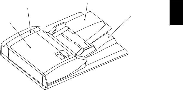
2.GENERAL DESCRIPTION
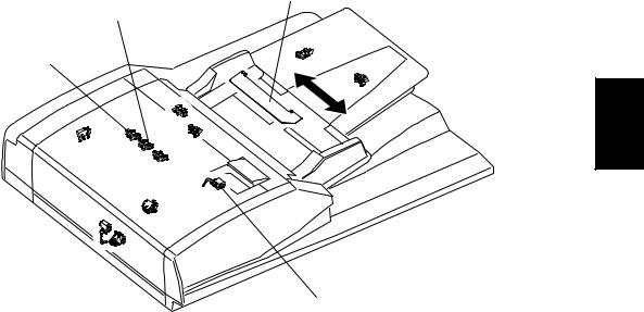
2.1Main Components
Original tray section |
|
Drive/Control section |
|
Original exit tray section |
2 |
Feeding/Transporting section |
|
|
Fig. 2-1 |
|
|
|
|
|
|
Location |
|
|
Components |
|
|
|
|
Feeding/Transporting |
Pickup roller |
|
Original empty sensor (S3) |
section |
Feed roller |
|
Original length detection sensor (S4) |
|
Separation roller |
|
Original registration sensor (S5) |
|
Registration roller |
|
Original width detection sensor-1 (S6) |
|
Intermediate transfer roller |
|
Original width detection sensor-2 (S7) |
|
Pre-reading roller |
|
Original intermediate transport sensor(S8) |
|
Post-reading roller |
|
Read sensor (S9) |
|
Exit/reverse roller |
|
Original exit/reverse sensor (S10) |
|
Reverse registration roller |
|
Jam access cover sensor (S11) |
Original tray section |
Original width guide |
|
Original tray sensor (S1) |
|
Original tray |
|
Original tray width sensor (S2) |
|
Original reverse tray |
|
|
Original exit tray section |
Original exit tray |
|
|
|
|
|
|
Drive/Control section |
|
|
Original feed motor (M1) |
|
|
|
Read motor (M2) |
|
|
|
Original exit/reverse motor (M3) |
|
|
|
Fan motor (M4) |
|
|
|
Original pickup solenoid (SOL1) |
|
|
|
Gate solenoid (SOL2) |
|
|
|
RADF opening/closing sensor (S12) |
|
|
|
Jam access cover opening/closing switch (SW1) |
|
|
|
RADF control PC board (ADF) |
© 2005 - 2011 TOSHIBA TEC CORPORATION All rights reserved |
MR-3018/3020/3021/3022 |
|
GENERAL DESCRIPTION |
2 - 1
06/09
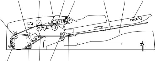
2.2Sectional View
R8 |
R4 R2 |
R3 R1 |
TRY2 |
TRY3 |
TRY1 |
R5
|
|
|
|
|
|
|
|
|
|
|
|
|
|
|
|
|
|
|
|
|
|
|
|
|
|
|
|
|
|
|
|
|
|
|
|
|
|
|
|
|
|
|
|
|
|
|
|
|
|
|
|
|
|
|
|
|
|
|
|
|
R6 |
R7 FLP1 R9 |
FLP2 |
|
|
|
|
||||||||||||
|
|
|
|
|
|||||||||||||||
|
|
|
|
|
|||||||||||||||
|
|
|
|
|
|
|
|
|
|
|
|
|
|
Fig. 2-2 |
|
|
|
|
|
|
|
|
|
|
|
|
|
|
|
|
|
|
|
|
|
|
|
|
|
TRY1 |
Original tray |
|
|
|
|
|
|
|
|
|
|
|
|
|
R3 |
Separation roller |
|||
|
|
|
|
|
|
|
|
|
|
|
|
|
|
|
|
|
|
|
|
TRY2 |
Original reverse tray |
|
|
|
|
R4 |
Registration roller |
||||||||||||
|
|
|
|
|
|
|
|
|
|
|
|
|
|
|
|
|
|
|
|
TRY3 |
Original exit tray |
|
|
|
|
|
|
|
|
|
|
|
|
|
R5 |
Intermediate transfer roller |
|||
|
|
|
|
|
|
|
|
|
|
|
|
|
|
|
|
|
|
|
|
FLP1 |
Exit gate |
|
|
|
|
|
|
|
|
|
|
|
|
|
R6 |
Pre-reading roller |
|||
|
|
|
|
|
|
|
|
|
|
|
|
|
|
|
|
|
|
|
|
FLP2 |
Reverse flap |
|
|
|
|
|
|
|
|
|
|
|
|
|
R7 |
Post-reading roller |
|||
|
|
|
|
|
|
|
|
|
|
|
|
|
|
|
|
|
|
|
|
R1 |
Pickup roller |
|
|
|
|
|
|
|
|
|
|
|
|
|
R8 |
Reverse registration roller |
|||
|
|
|
|
|
|
|
|
|
|
|
|
|
|
|
|
|
|
|
|
R2 |
Feed roller |
|
|
|
|
|
|
|
|
|
|
|
|
|
R9 |
Exit/reverse roller |
|||
|
|
|
|
|
|
|
|
|
|
|
|
|
|
|
|
|
|
|
|
MR-3018/3020/3021/3022 |
© 2005 - 2011 TOSHIBA TEC CORPORATION All rights reserved |
GENERAL DESCRIPTION |
|
2 - 2
06/09

2.3Electric Parts Layout
|
ADF |
SOL1 |
SOL2 |
M1 |
|
M4 |
2 |
|
M2
M3
|
S2 |
S12 |
S11 |
S3 |
S1 |
|
S7 S6 S5
SW1
S9
S8 |
S4 |
S10
Fig. 2-3
© 2005 - 2011 TOSHIBA TEC CORPORATION All rights reserved |
MR-3018/3020/3021/3022 |
|
GENERAL DESCRIPTION |
2 - 3
06/09
2.4Symbols and Functions of Various Components
1) Motors
Symbol |
Name |
Function |
|
|
|
M1 |
Original feed motor |
Drives the original feed roller, pickup roller and registration roller. |
|
|
|
M2 |
Read motor |
Transports originals by driving the intermediate transport roller, |
|
|
front read roller, rear read roller and reverse registration roller. |
M3 |
Original exit/reverse motor |
Drives the original exit/reverse roller. |
|
|
|
M4 |
Fan motor |
Cools off the ADF drive section and ADF board. |
|
|
|
2) Sensors and Switches
Symbol |
Name |
Function |
|
|
|
S1 |
Original tray sensor |
Detects the length of the original set on the original tray. |
|
|
|
S2 |
Original tray width sensor |
Detects the width of the original set on the original tray. |
|
|
|
S3 |
Original empty sensor |
Detects the original set on the original tray. |
|
|
|
S4 |
Original length detection |
Detects the length of the original. |
|
sensor |
|
S5 |
Original registration sensor |
Detects transport of the original at the registration roller section. |
|
|
|
S6 |
Original width detection sen- |
Detects the width of the original. |
|
sor-1 |
|
S7 |
Original width detection sen- |
Detects the width of the original. |
|
sor-2 |
|
|
|
|
S8 |
Original intermediate trans- |
Detects the original transported to the Pre-scanning section. |
|
port sensor |
|
S9 |
Read sensor |
Detects the leading edge of the original at the original scanning section. |
|
|
|
S10 |
Original exit/reverse sensor |
Detects the exit (transit) of an original. Also detects the stop reference |
|
|
position for an original when in reverse. |
S11 |
Jam access cover sensor |
Detects opening/closing of the Jam access cover. |
|
|
|
S12 |
RADF opening/closing sen- |
Detects opening/closing of the RADF. |
|
sor |
|
|
|
|
SW1 |
Jam access cover opening/ |
Switches between cutoff and supply state of the 24 V power by open- |
|
closing switch |
ing/closing of the jam access cover. |
3) Solenoid
Symbol |
Name |
Function |
|
|
|
SOL1 |
Original pickup solenoid |
Drives up and down the original pickup roller. |
|
|
|
SOL2 |
Gate solenoid |
Drives the reverse flap. (Switches the flap to the reverse side when |
|
|
turned to ON.) |
4) PC board
Symbol |
Name |
Function |
|
|
|
ADF |
RADF control PC board |
Controls the RADF. |
|
(ADF board) |
|
MR-3018/3020/3021/3022 |
© 2005 - 2011 TOSHIBA TEC CORPORATION All rights reserved |
GENERAL DESCRIPTION |
|
2 - 4
06/06
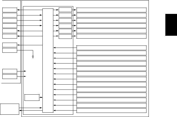
2.5Diagram of Signal Blocks
Equipment |
RADF |
|
|
|
RxD |
|
Driver |
Original feed motor (M1) |
|
TxD |
|
Driver |
Read motor (M2) |
|
REQ |
|
Driver |
Original exit/reverse motor (M3) |
2 |
ACK |
|
Driver |
Fan motor (M4) |
|
DF-REQ |
|
Driver |
Original pickup solenoid (SOL1) |
|
DF-ACK |
|
Driver |
Gate solenoid (SOL2) |
|
SCAN-ST |
|
|
Original tray sensor (S1) |
|
CNT |
|
|
|
|
|
|
Original tray width sensor (S2) |
|
|
|
|
|
|
|
|
|
|
Original empty sensor (S3) |
|
|
CPU |
|
Original length detection sensor (S4) |
|
DC 24V |
|
|
Original registration sensor (S5) |
|
|
|
Original width detection sensor-1 (S6) |
|
|
DC 5V |
|
|
|
|
|
|
Original width detection sensor-2 (S7) |
|
|
|
|
|
|
|
|
|
|
Original intermediate transport sensor (S8) |
|
|
|
|
Read sensor (S9) |
|
|
Reset IC |
|
Original exit/reverse sensor (S10) |
|
|
|
Jam access cover sensor (S11) |
|
|
|
|
|
|
|
|
|
|
RADF opening/closing sensor (S12) |
|
Downlad jig |
|
|
Jam access cover opening/closing switch (SW1) |
|
|
|
|
|
|
|
|
|
Fig. 2-4 |
|
© 2005 - 2011 TOSHIBA TEC CORPORATION All rights reserved |
MR-3018/3020/3021/3022 |
|
GENERAL DESCRIPTION |
2 - 5
09/05
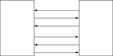
2.6Description of Interface Signals
The following 6 lines are used to transmit/receive signals between the equipment and the RADF.
REQ ...................... |
Communication request signal (from equipment to the RADF) |
DF-REQ ................ |
Communication request signal (from the RADF to equipment) |
DF-ACK................. |
Communication request acknowledging signal (from the RADF to equipment) |
ACK....................... |
Communication request acknowledging signal (from equipment to the RADF) |
TxD ....................... |
Data transmitted from equipment to the RADF |
RxD ....................... |
Data transmitted from the RADF to equipment |
Data communication (RxD and TxD) between the scanner and the RADF has adopted the serial communication system which does not allow checking using testing devices to see whether the signals are transmitted/received properly in the field.
RADF |
Equipment |
REQ
DF-ACK
TxD
DF-REQ
ACK
RxD
Fig. 2-5
MR-3018/3020/3021/3022 |
© 2005 - 2011 TOSHIBA TEC CORPORATION All rights reserved |
GENERAL DESCRIPTION |
|
2 - 6
05/12
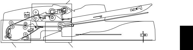
3.DESCRIPTION OF OPERATIONS
3.1DRIVE SYSTEM
Feed motor drive section
|
3 |
Read motor drive section |
Exit/reverse motor drive section |
|
Fig. 3-1 |
3.1.1Outline
Originals are transported by the original feed motor, read motor and original exit/reverse motor. Each motor has a drive section for the following operations:
Original feed motor drive section: |
picks up originals and drives the registration roller. |
Read motor drive section: |
transports originals and drives parts such as the pre-reading |
roller.
Original exit/reverse motor drive section: exits and reverses originals, and drives the exit/reverse roller.
The Original feed motor rotates reversely when the originals are being transported at the registration roller, compared to its rotational direction when they are being picked up.
The original exit/reverse motor also rotates reversely when the originals are being reversed and transported, compared to its rotational direction when they are being exited.
The read motor always rotates in a constant direction.
© 2005 - 2011 TOSHIBA TEC CORPORATION All rights reserved |
MR-3018/3020/3021/3022 |
|
DESCRIPTION OF OPERATIONS |
3 - 1
06/09
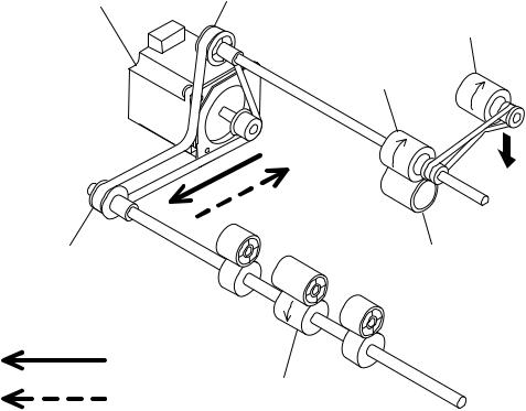
3.1.2Original feed motor drive section
Original feed motor |
Oneway clutch |
Pickup roller
Feed roller
Oneway clutch |
Separation roller |
Pickup
Registration roller
Feed
Fig. 3-2
When an original is placed on the original tray and the RADF receives a feed request signal from the equipment, the feeding of the original is started.
The original empty sensor detects the presence of the original, and then the pickup roller is lowered by the drive from the original pickup solenoid.
The Original feed motor rotates, and the pickup roller and the feed roller then rotate in a normal direction (shown in a solid line in the figure) to guide the original into the transport path. Then the original is transported to the registration roller to be aligned.
The original aligned with the registration roller is then transported by the reverse rotation of the Original feed motor (shown in a dotted line in the figure).
A one-way clutch is installed inside of each gear of the feed roller and the registration roller, so these gears will not be driven in a reverse rotation.
When the original empty sensor detects that there is no original on the original tray, the original pickup solenoid is turned OFF and the pickup roller is raised.
The original pickup solenoid is the one can operate both suction and recovery.
MR-3018/3020/3021/3022 |
© 2005 - 2011 TOSHIBA TEC CORPORATION All rights reserved |
DESCRIPTION OF OPERATIONS |
|
3 - 2
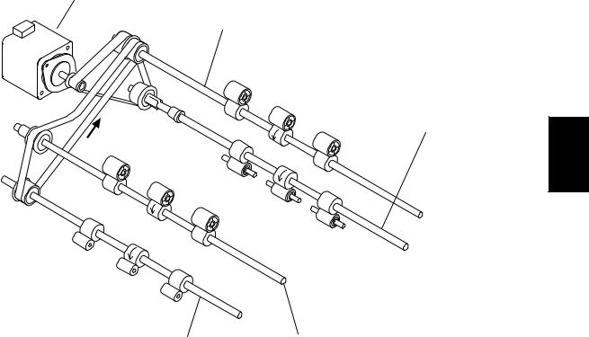
3.1.3Read motor drive section
Read motor
Reverse registration roller
Post-reading roller
3
Pre-reading roller |
Intermediate transfer roller |
Fig. 3-3
The transported original is driven by the read motor.
Then the original is transported to a scanning start position by the intermediate transfer roller and prereading roller.
The original transported to the scanning start position is then scanned in the scanner function of the equipment.
When the data of the original have been scanned, the original is then transported to the original exit tray side by the post-reading roller.
© 2005 - 2011 TOSHIBA TEC CORPORATION All rights reserved |
MR-3018/3020/3021/3022 |
|
DESCRIPTION OF OPERATIONS |
3 - 3
06/06
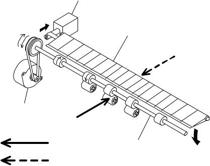
3.1.4Original exit/reverse motor drive section
Gate solenoid
Reverse flap
Exit/reverse motor
Exit |
Exit/reverse roller |
|
Reverse
Fig. 3-4
When the data of the original have been scanned, the original is exited to the original exit tray by the exit/reverse roller driven by the exit motor (shown in a solid line in the figure).
In the duplex scanning mode, the gate solenoid is turned ON and the reverse flap is lowered to switch the transport path to the reverse tray side when the scanning of one side of the original is completed. When the reverse flap is lowered, the original is temporarily transported to the reverse tray, and then the exit motor rotates reversely to return the original to the transport path switched for reverse operation (shown in a dotted line in the figure).
The reversed original is aligned with the reverse registration roller, and then the other side of the original is scanned. When the scanning is completed, the original is exited to the original exit tray.
MR-3018/3020/3021/3022 |
© 2005 - 2011 TOSHIBA TEC CORPORATION All rights reserved |
DESCRIPTION OF OPERATIONS |
|
3 - 4
06/09
3.2Original Size Detection
The original tray width sensor, original length detection sensor, and original width detection sensors-1 and -2 work in combination to detect the size of originals.
Original tray width sensor
Original width detection sensor-1
Original width detection sensor-2
3 |
Original length detection sensor
Fig. 3-5
3.2.1Outline
When an original is placed on the original tray, the width of the original is detected by the positions of the original width guides. Then the original width sensors -1 and -2 and the original length detection sensor detect the size of the original being transported. Based on the detection result of these sensors, the size of the original is finally determined.
3.2.2Original tray width sensor
The original tray width sensor detects the width of an original placed on the original tray.
It is detected by the brush attached to the rack moving on the original tray width sensor, which is a board with the different length of the patterns written.
This brush is moved as the original width guide is moved. Signals (TWID0S, TWID1S, TWID2S) are opened and shorted to SG by this movement.
The combination of these short (= low level) and open (= high level) can determine the width of the original.
Sizes detectable in combination of these open and short of the signals are as follows:
TWID2S |
TWID1S |
TWID0S |
|
Original width size |
Original width size |
|
(LT series) |
(A4 series) |
|||
|
|
|
|
||
L |
H |
H |
|
- |
B5-R |
H |
L |
H |
|
ST-R |
A5-R |
L |
L |
H |
|
LD / LT |
A3 / A4 |
L |
H |
L |
|
8.5 x 8.5 / LT-R / LG / 13"LG |
A4-R / FOLIO |
L |
L |
L |
|
COMPUTER |
B4 / B5 |
|
H (= high level): Open |
L (= low level): Short |
|
||
© 2005 - 2011 TOSHIBA TEC CORPORATION All rights reserved |
MR-3018/3020/3021/3022 |
|
DESCRIPTION OF OPERATIONS |
3 - 5
11/12
3.2.3Original width detection sensors-1 and -2 / Original length
detection sensor
The size of the original is determined by the detection performed in combination of the original width detection sensors-1 and -2 and the original length detection sensor, as well as the detection performed by the original tray width sensor.
Sizes detectable in combination of these sensors are as follows:
A4 series (ORG-SRS: 1)
Original length |
Original width |
Original width |
Size determined |
Original tray width |
|
detection sensor |
sensor-1 |
sensor-2 |
|||
|
|
||||
|
OFF |
OFF |
A5-R |
- |
|
OFF |
|
|
|
|
|
ON |
OFF |
B5 |
- |
||
|
|
|
|
|
|
|
ON |
ON |
A4 |
- |
|
|
|
|
|
|
|
|
OFF |
OFF |
B5-R |
- |
|
|
|
|
|
|
|
ON |
ON |
OFF |
A4-R / FOLIO |
Determined by a gap |
|
B4 |
between guides |
||||
|
|
|
|||
|
|
|
|
|
|
|
ON |
ON |
A3 |
- |
|
|
|
|
|
|
A4 series (width sizes mixed at A3 / A4 standard)
Original length |
Original width |
Original width |
Size determined |
Original tray width |
|
detection sensor |
sensor-1 |
sensor-2 |
|||
|
|
||||
|
|
|
|
|
|
|
ON |
ON |
A3 |
|
|
ON |
|
|
|
|
|
OFF |
OFF |
A4-R / FOLIO |
|
||
|
|
|
|
A3 / A4 |
|
|
ON |
OFF |
B4 |
||
|
|
|
|
|
|
OFF |
ON |
OFF |
B5 |
|
|
|
|
|
|
||
ON |
ON |
A4 |
|
||
|
|
||||
|
|
|
|
|
A4 series (width sizes mixed at B4 / B5 standard)
Original length |
Original width |
Original width |
Size determined |
Original tray width |
|
detection sensor |
sensor-1 |
sensor-2 |
|||
|
|
||||
ON |
OFF |
OFF |
A4-R / FOLIO |
|
|
|
|
|
|
||
ON |
OFF |
B4 |
B4/B5 |
||
|
|||||
|
|
|
|
||
OFF |
ON |
OFF |
B5 |
||
|
|||||
|
|
|
|
||
OFF |
OFF |
A5-R |
|
||
|
|
||||
|
|
|
|
|
A4 series (width sizes mixed at A4-R standard)
Original length |
Original width |
Original width |
Size determined |
Original tray width |
|
detection sensor |
sensor-1 |
sensor-2 |
|||
|
|
||||
ON |
OFF |
OFF |
B5-R |
|
|
|
|
|
|
||
ON |
OFF |
A4-R / FOLIO |
A4-R |
||
|
|||||
|
|
|
|
|
|
OFF |
OFF |
OFF |
A5-R |
|
|
|
|
|
|
|
A4 series (width sizes mixed at B5-R standard)
Original length |
Original width |
Original width |
Size determined |
Original tray width |
|
detection sensor |
sensor-1 |
sensor-2 |
|||
|
|
||||
ON |
OFF |
OFF |
B5-R |
B5-R |
|
|
|
|
|
||
OFF |
OFF |
OFF |
A5-R |
||
|
|||||
|
|
|
|
|
MR-3018/3020/3021/3022 |
© 2005 - 2011 TOSHIBA TEC CORPORATION All rights reserved |
DESCRIPTION OF OPERATIONS |
|
3 - 6
LT series (ORG-SRS: 0)
Original length |
Original width |
Original width |
Size determined |
Original tray width |
|
detection sensor |
sensor-1 |
sensor-2 |
|||
|
|
||||
|
OFF |
OFF |
ST-R |
- |
|
OFF |
ON |
OFF |
8.5x8.5 |
- |
|
|
ON |
ON |
A4 |
- |
|
ON |
ON |
OFF |
LT-R / LG / COMP / 13”LG |
- |
|
ON |
ON |
LD |
- |
||
|
LT series (width sizes mixed at LD / LT standard)
Original length |
Original width |
Original width |
Size determined |
Original tray width |
|
detection sensor |
sensor-1 |
sensor-2 |
|||
|
|
||||
|
ON |
ON |
LD |
|
|
ON |
ON |
OFF |
COMP |
LD / LT |
|
|
OFF |
OFF |
LT-R / LG / 8.5x8.5 / 13”LG |
||
|
|
||||
OFF |
ON |
ON |
LT |
|
3 |
LT series (width sizes mixed at LG / LT-R standard)
Original length |
Original width |
Original width |
Size determined |
Original tray width |
|
detection sensor |
sensor-1 |
sensor-2 |
|||
|
|
||||
ON |
ON |
OFF |
LT-R / LG / 8.5x8.5 / 13”LG |
LD / LT |
|
OFF |
OFF |
OFF |
ST-R |
||
|
© 2005 - 2011 TOSHIBA TEC CORPORATION All rights reserved |
MR-3018/3020/3021/3022 |
|
DESCRIPTION OF OPERATIONS |
3 - 7
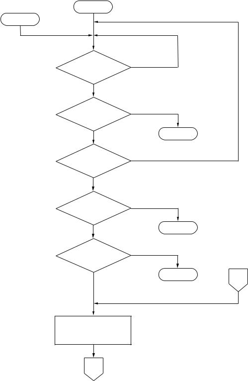
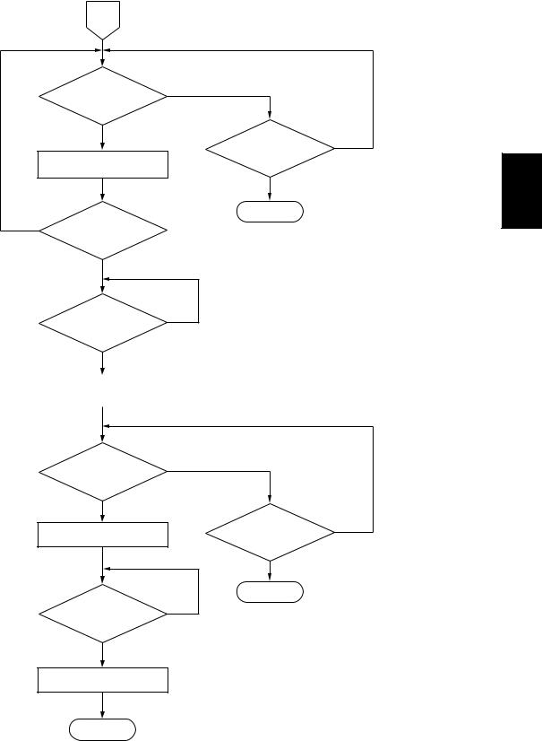
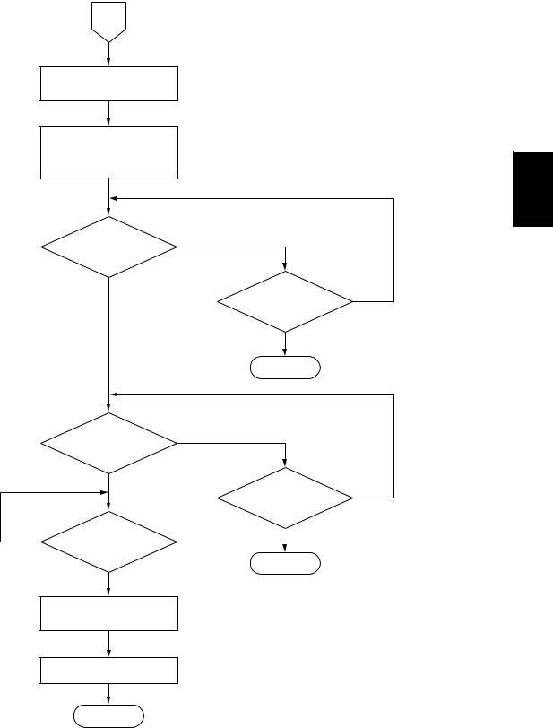
3.3FLOW CHART
Power ON
Standby
RADF jam access |
YES |
cover OPEN? |
|
NO |
|
All sensors OFF? |
NO |
|
|
YES |
Jam |
Empty sensor ON? |
NO |
|
|
YES |
|
Feed request |
NO |
signal received? |
|
YES |
Standby |
|
Original on |
NO |
|
feeding tray? |
|
|
YES |
Jam |
D |
|
Pickup solenoid ON, pickup roller goes down, feed motor rotates forward.
A
MR-3018/3020/3021/3022 |
© 2005 - 2011 TOSHIBA TEC CORPORATION All rights reserved |
DESCRIPTION OF OPERATIONS |
|
3 - 8
A
Original |
|
registration |
NO |
|
|
||
sensor |
|
ON? |
|
|
|
YES |
|
|
|
|
|
Feed motor stops after transporting for a certain period of time.
A certain period |
NO |
|
of time passed? |
|
|
|
YES |
|
|
|
|
|
|
|
Registration roller rotates. (Feed motor rotates reverse.)
Read motor rotates.
|
|
|
|
|
|
|
|
|
|
Paper transported |
NO |
|||
before the intermediate |
||||
|
||||
transport roller? |
|
|||
|
YES |
|
||
|
|
|||
|
|
|
|
|
Feed motor rotation speed switches. First scan: Highest speed
Second scan/later: Requested speed
B
A certain period |
NO |
of time passed? |
3 |
|
|
YES |
|
Jam |
|
Monitoring registration sensor by parallel processing.
Feed motor stops when registration sensor detects trailing edge of original. Skip to D .
© 2005 - 2011 TOSHIBA TEC CORPORATION All rights reserved |
MR-3018/3020/3021/3022 |
|
DESCRIPTION OF OPERATIONS |
3 - 9
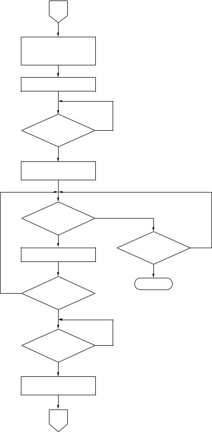
B
Original |
intermediate |
NO |
transport |
sensor ON? |
|
|
YES |
|
|
|
|
|
|
|
Feed motor and read motor |
|
|
stop after transporting for |
|
|
certain period of time. |
|
|
|
|
|
A certain period |
NO |
of time passed? |
|
YES |
|
Jam |
|
Feed request signal |
NO |
|
|
received? |
|
YES
YES
Duplex?
NO
E
Registration roller also rotates, while read motor rotates
and registration sensor ON.
Transport for |
NO |
|
a certain amount of |
||
|
||
distance completed? |
|
|
YES |
|
|
Scanning start signal |
Exposure and scanning start. |
|
sent (level: High) |
||
|
||
C |
|
MR-3018/3020/3021/3022 |
© 2005 - 2011 TOSHIBA TEC CORPORATION All rights reserved |
DESCRIPTION OF OPERATIONS |
|
3 - 10
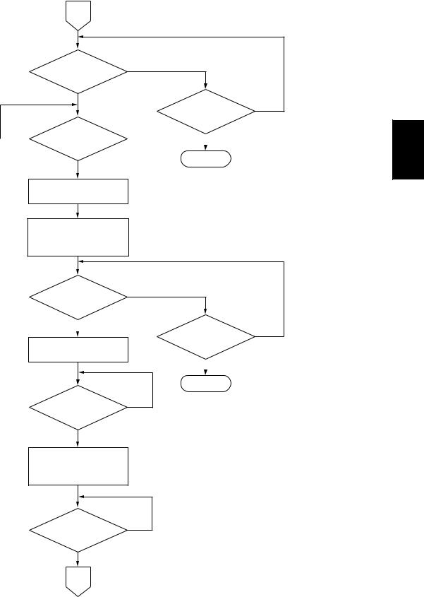
C |
|
|
Original exit/reverse |
NO |
|
|
|
|
sensor ON? |
|
|
YES |
|
|
|
A certain period |
NO |
Original exit/reverse |
of time passed? |
|
|
|
|
motor rotates. |
|
|
|
YES |
|
|
Jam |
|
NO |
|
|
Read sensor OFF? |
|
|
YES |
|
|
A certain period |
NO |
of time passed? |
|
YES
Scanning start signal |
Scanning completed. |
|
sent (level: High) |
||
|
||
|
|
D |
NO |
|
Original exit/reverse |
|
|
|
|
|
sensor OFF? |
|
|
YES |
|
|
Read motor stops. |
A certain period |
NO |
of time passed? |
|
|
|
|
YES
|
Jam |
|
Transport for |
NO |
|
a certain amount of |
||
|
||
distance completed? |
|
YES
Original exit/reverse motor stops.
END
© 2005 - 2011 TOSHIBA TEC CORPORATION All rights reserved |
MR-3018/3020/3021/3022 |
|
DESCRIPTION OF OPERATIONS |
3 |
3 - 11
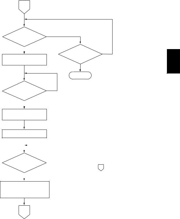
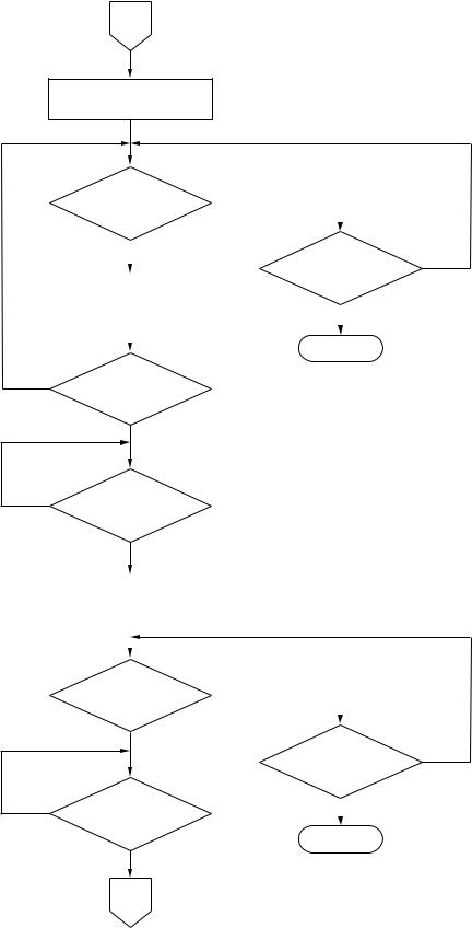
E
Registration roller also rotates, while read motor rotates
and registration sensor ON.
Gate solenoid ON
Transport for |
NO |
|
a certain amount of |
||
|
||
distance completed? |
|
YES
Scanning start signal
Exposure and scanning start.
sent (level: High)
Original exit/reverse |
NO |
|
|
|
|
sensor ON? |
|
|
YES |
|
|
|
A certain period |
NO |
Original exit/reverse |
of time passed? |
|
motor rotates. |
|
|
|
YES |
|
|
Jam |
|
Read sensor OFF? |
|
|
YES |
|
A certain period |
NO |
of time passed? |
|
YES
Scanning start signal
Scanning completed.
sent (level: Low)
F
MR-3018/3020/3021/3022 |
© 2005 - 2011 TOSHIBA TEC CORPORATION All rights reserved |
DESCRIPTION OF OPERATIONS |
|
3 - 12
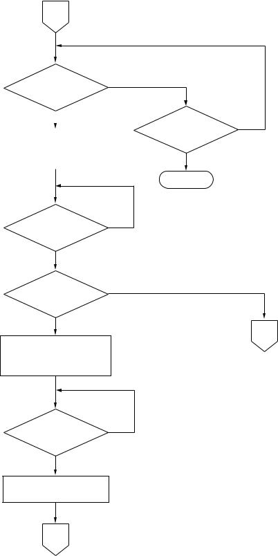
F |
|
|
Original exit/reverse |
NO |
|
sensor OFF? |
|
|
YES |
A certain period |
NO |
|
||
|
of time passed? |
|
NO |
|
Transport for |
YES |
a |
certain amount of |
||
|
distance completed? |
|
|
Jam
YES
Original exit/reverse motor and read motor stop.
After a certain period of time, original exit/reverse motor reverses, read motor starts, reverse roller
aligns original, and then system reboots.
Original intermediate |
NO |
|
transport sensor ON? |
|
|
|
YES |
|
|
|
|
|
|
|
Exit/reverse and read motor stop after transporting for
a certain amount of distance.
A certain period |
NO |
|
of time passed? |
|
|
|
YES |
|
|
|
|
|
|
|
|
Jam |
Transport request |
NO |
signal received? |
|
YES |
|
Read motor and exit/reverse motor rotate at requested speed.
Transport for
a certain amount of NO distance completed?
YES
G
© 2005 - 2011 TOSHIBA TEC CORPORATION All rights reserved |
MR-3018/3020/3021/3022 |
|
DESCRIPTION OF OPERATIONS |
3 |
3 - 13
G
Scanning start signal
Exposure and scanning start.
sent (level: High)
Original |
exit/reverse |
NO |
|
||
sensor |
ON? |
|
|
|
|
|
YES |
|
|
|
|
|
|
|
A certain period |
NO |
|
|
|
|
of time passed? |
|
|
Original exit/reverse |
|
||||
|
|
|
|||
motor rotates. |
|
|
|
||
|
|
|
|||
|
|
|
|
YES |
|
|
|
|
|
|
|
|
|
|
Jam |
|
|
|
|
|
|
||
NO
Read sensor OFF?
|
YES |
NO |
A certain period |
|
of time passed? |
YES
Scanning start signal |
Scanning completed. |
||
sent (level: Low) |
|||
|
|||
|
|
|
|
|
|
|
|
Original exit/reverse |
NO |
|
|
sensor OFF? |
|
|
|
|
YES |
|
NO |
Transport for |
|
a certain amount of |
||
|
||
|
distance completed? |
A certain period |
NO |
|
|
||
of time passed? |
|
|
|
YES |
|
|
|
|
|
|
|
Jam
YES
H
MR-3018/3020/3021/3022 |
© 2005 - 2011 TOSHIBA TEC CORPORATION All rights reserved |
DESCRIPTION OF OPERATIONS |
|
3 - 14
H
Original exit/reverse motor |
|
|
and read motor stop. |
|
|
After a certain period of time, |
|
|
original exit/reverse motor reverses, |
|
|
read motor starts, reverse roller |
|
|
aligns original, and then system reboots. |
|
|
|
|
3 |
Original intermediate |
NO |
|
transport sensor ON? |
|
|
YES |
|
|
|
A certain period |
NO |
|
of time passed? |
|
|
YES |
|
|
Jam |
|
Original exit/reverse |
NO |
|
|
|
|
sensor OFF? |
|
|
YES |
|
|
|
A certain period |
NO |
|
of time passed? |
|
NO |
Transport for |
|
YES |
|
|||
a certain amount of |
|
||
|
distance completed? |
|
|
Jam
YES
Original exit/reverse motor and read motor stop.
Gate solenoid OFF
END
© 2005 - 2011 TOSHIBA TEC CORPORATION All rights reserved |
MR-3018/3020/3021/3022 |
|
DESCRIPTION OF OPERATIONS |
3 - 15
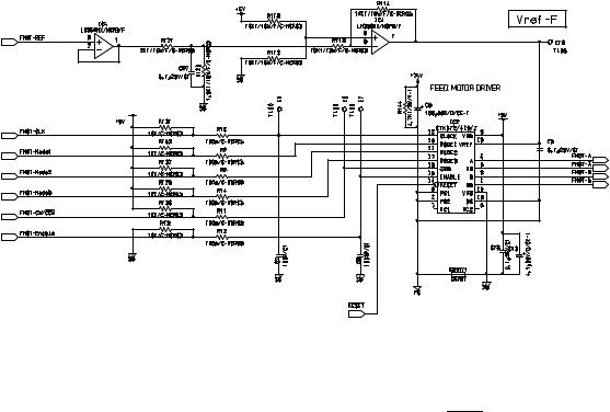
3.4DESCRIPTION OF CIRCUIT
3.4.1Drive Circuit for Feed Motor
Fig. 3-6 |
This circuit controls the rotation/stoppage and the direction of rotation, excitation mode and motor current of the feed motor.
A drive clock signal (FMOT-CLK) and rotation direction signal (FMOT-CW/CCW) are input to control the speed and direction of the motor rotation.
When the level of the enabling signal (FMOT-Enable) is set to "L", motor current is turned OFF regardless of the state of other signals.
For the excitation mode, either of 2 phase excitation, 1-2 phase excitation, W1-2 phase excitation, 2W1-2 phase excitation or the 4W1-2 phase excitation can be selected using the excitation switching signal (FMOT-Mode1/FMOT-Mode2).
The edge switching signal (FMOT-Mode3) is used to specify the switching timing for excitation phase either from when both the rise and decay edge of the CLK input are detected or when only the rising edge is detected.
Motor current value can be set discretionary by changing the level of the reference setting signal (FMOT-REF).
MR-3018/3020/3021/3022 |
© 2005 - 2011 TOSHIBA TEC CORPORATION All rights reserved |
DESCRIPTION OF OPERATIONS |
|
3 - 16
Loading...