


INSTALLATION MANUAL MANUEL D’INSTALLATION INSTALLATIONS-HANDBUCH MANUALE DI INSTALLAZIONE MANUAL DE INSTALACIÓN MANUAL DE INSTALAÇÃO INSTALLATIE HANDLEIDING
ЕГЧЕЙСЙДЙП ЕГКБФБУФБУЗУ
SUPER MODULAR MULTI SYSTEM AIR CONDITIONER
SMMS CLIMATISEUR
SMMS KLIMAGERÄ T
SMMS CONDIZIONATORE D'ARIA
SMMS APARATO DE AIRE ACONDICIONADO
SMMS AR CONDICIONADO
SMMS AIRCONDITIONER
SMMS КЛЙМБФЙУФЙКП
SMMS
Indoor Unit Unité intérieure Raumeinheit Unità interna Unidad interior Unidade interior Binnenunit
ЕущфесйкЮ mпнЬдб
For commercial use (Not accessible to the general public) Pour usage commercial (Vente interdite au grand public)
Nur fü r gewerbliche Nutzung (kein öffentlicher Zugang)
Per uso commerciale (Non accessibile a clienti generici) Para uso comercial (no destinado al público en general) Para uso comercial (não acessível ao público em geral)
Voor commercieel gebruik (niet geschikt voor huishoudelijk gebruik)
Гйб емрпсйкЮ чсЮуз (Мз дйбиЭуймп уфп ехсэ кпйнь)
<High-Wall Type> <Type mural haut> <Wand modell> <Tipo per mura alte>
<Tipo parte alta de la pared> <Tipo para Parede Alta> <Hogewandmodel>
<Фэрпт фпрпиефзмЭнпх шзлЬ уфпн фпЯчп>
MMK-AP0072H, MMK-AP0092H, MMK-AP0122H

ADOPTION OF NEW REFRIGERANT
This Air Conditioner is a new type which adopts a new refrigerant HFC (R410A) instead of the conventional refrigerant R22 in order to prevent destruction of the ozone layer.
Thank you very much for purchasing TOSHIBA Air Conditioner.
Please read this Installation manual carefully before using your Air Conditioner.
•Be sure to obtain the “Owner’s manual” and “Installation manual” from constructor (or dealer).
Request to constructor or dealer
Please clearly explain the contents of the Owner’s manual and hand over it.
UTILISATION DU NOUVEAU REFRIGERANT
Ce climatiseur est d’un type inédit qui utilise le nouveau réfrigérant HFC (R410A) au lieu du réfrigérant traditionnel R22, afin d’éviter la destruction de la couche d’ozone.
Nous vous remercions pour avoir choisi un climatiseur TOSHIBA.
Veuillez lire attentivement ce Manuel d’installation avant d’utiliser votre climatiseur.
•Assurez-vous que le constructeur (ou le revendeur) vous remette le “Manuel du propriétaire” et le “Manuel d’installation”.
Demande au constructeur ou au revendeur
Veuillez expliquer clairement le contenu du Manuel du propriétaire et le remettre au client.
EINFÜ HRUNG EINES NEUEN KÜ HLMITTELS
Dies ist ein neuartiges Klimagerät. Anstatt des herkömmlichen Kühlmittels R22 verwendet es das neue ozonschicht-schonende HFC Kühlmittel R410A.
Wir danken Ihnen, dass Sie sich für ein TOSHIBA Klimagerät entschieden haben.
Bitte lesen Sie diese Installations-Handbuch, bevor Sie Ihr Klimagerät benutzen, sorgfältig.
•Lassen Sie sich die “Betriebsanleitung” und das “Installations-Handbuch” unbedingt vom Installateur oder vom Lieferanten aushändigen.
Eine Bitte an den Installateur oder Lieferanten:
Bitte erklären Sie dem Käufer den Inhalt der Betriebsanleitung und händigen sie ihm aus.
ADOZIONE DI UN NUOVO REFRIGERANTE
Questo condizionatore d'ariaè di un tipo nuovo che adotta un nuovo refrigerate HFC (R410A) al posto del refrigerante convenzionale R22, per prevenire la distruzione dello strato di ozono dell'atmosfera terrestre.
Grazie di aver acquistato un condizionatore d'aria TOSHIBA.
Prima di usare il condizionatore d'aria, leggere con attenzione questo Manuale di installazione.
•Si raccomanda di tenere a portata di mano il “Manuale del proprietario” e il “Manuale di installazione” ricevuti dal produttore (o dal rivenditore).
Richiesta al produttore o al rivenditore
Spiegare chiaramente il contenuto del Manuale del proprietario e consegnarne una copia all'utente.
ADOPCIÓ N DE NUEVO REFRIGERANTE
Este aparato de aire acondicionado es un modelo reciente que incorpora el nuevo refrigerante HFC (R410A) en lugar del refrigerante convencional R22 para asíevitar daños en la capa de ozono.
Muchas gracias por haber adquirido el aparato de aire acondicionado TOSHIBA. Lea atentamente este Manual de instalación antes de utilizar el aparato de aire acondicionado.
•Asegúrese de que el fabricante (o distribuidor) le proporcione el “Manual del propietario” y el “Manual de instalación”.
Solicitud al fabricante o distribuidor
Explique con claridad el contenido del Manual del propietario y entréguelo al cliente.
ADOPÇÃ O DO NOVO REFRIGERANTE
Este ar condicionado é um modelo novo que adopta um novo refrigerante HFC (R410A) em vez do refrigerante convencional R22 para evitar a destruição da cama de ozono.
Muito obrigada por adquirir o Ar Condicionado TOSHIBA.
Leia atentamente este Manual de inslatação antes de utilizar o seu ar condicionado.
•Não se esqueça de receber o “Manual do utilizador” e o “Manual de inslatação” do fabricante (ou agente).
Pedido ao fabricante ou agente
Explique por favor o conteúdo do Manual do utilizador e entregue-o.
TOEPASSING VAN EEN NIEUW KOELMIDDEL
Deze airconditioner is een nieuwe type dat werkt met een nieuw koelmiddel HFC (R410A) in plaats van met het conventionele koelmiddel R22, als bijdrage om de aantasting van de ozonlaag te reduceren.
Hartelijk dank voor uw keuze voor een airconditioner van TOSHIBA.
Lees deze installatiehandleiding zorgvuldig door voordat u de airconditioner gaat gebruiken.
•Zorg ervoor dat u zowel de “gebruiksaanwijzing” als de
“installatiehandleiding” van de installateur (of leverancier) krijgt.
Verzoek aan de installateur of de leverancier
Leg de inhoud van de gebruiksaanwijzing duidelijk uit en overhandig de gebruiksaanwijzing nadien aan de klant.
ХЙПИЕФЗУЗ НЕПХ ШХКФЙКПХ |
Убт ехчбсйуфпэме рплэ рпх рспфймЮубфе гйб фзн бгпсЬ убт Энб |
|
Клймбфйуфйкь TOSHIBA. |
||
Фп рбсьн Клймбфйуфйкь еЯнбй нЭпт фэрпт рпх хйпиефеЯ нЭп |
Рбсбкблпэме дйбвЬуфе рспуечфйкЬ фйт ЕгчейсЯдйп ЕгкбфЬуфбузт рсйн брь фз |
|
чсЮуз фпх Клймбфйуфйкпэ. |
||
шхкфйкь HFC (R410A) уфз иЭуз фпх ухмвбфйкпэ |
• ВевбйщиеЯфе ьфй п кбфбукехбуфЮт (Ю п рщлзфЮт) убт рбсЭдщуе кбй фйт |
|
шхкфйкпэ R22 рспкеймЭнпх нб впзиЮуей уфзн рспуфбуЯб |
“ПдзгЯет ЧсЮузт” кбй фп “ЕгчейсЯдйп ЕгкбфЬуфбузт”. |
|
фпх ьжпнфпт. |
РбсЬклзуз гйб фпн кбфбукехбуфЮ Ю фпн рщлзфЮ |
|
Рбсбкблю еозгЮуфе ме убцЮнейб фб ресйечьменб фщн Пдзгйюн ЧсЮузт кбй |
||
|
||
|
|


 HFC
HFC
 R410A
R410A


 R22
R22

|
|
CONTENTS |
|
ENGLISH |
|||
Accessory parts and parts to be procured locally ....................................... |
1 |
7 |
DRAINAGE |
9 |
|||
1 |
PRECAUTIONS FOR SAFETY |
2 |
|||||
8 |
REFRIGERANT PIPING |
10 |
|||||
2 |
SELECTION OF INSTALLATION PLACE |
3 |
|||||
9 |
ELECTRIC WORK |
12 |
|||||
3 |
INSTALLATION OF INDOOR UNIT |
5 |
|||||
10 |
APPLICABLE CONTROLS |
16 |
|||||
4 |
CUTTING A HOLE AND MOUNTING INSTALLATION PLATE |
6 |
|||||
11 |
TEST RUN ............................................................................................ |
18 |
|||||
5 |
PIPING AND DRAIN HOSE INSTALLATION .......................................... |
7 |
12 |
TROUBLESHOOTING |
20 |
|
|
6 |
INDOOR UNIT FIXING |
9 |
|
||||
|
|
|
|
||||
|
|
|
|
|
|
|
|
|
|
SOMMAIRE |
|
FRANCAIS |
||
Piè ces accessoires et piè ces non fournies ................................................ |
25 |
6 |
FIXATION DE L’UNITÉ INTÉ RIEURE ................................................... |
33 |
||
1 |
MESURES DE SECURITE ................................................................... |
26 |
7 |
É VACUATION ........................................................................................ |
33 |
|
2 |
SELECTION DU LIEU D’INSTALLATION ............................................. |
27 |
8 |
TUYAUX DE RÉ FRIGÉ RANT ............................................................... |
34 |
|
3 |
INSTALLATION DE L’UNITE INTERIEURE .......................................... |
29 |
9 |
TRAVAUX D’É LECTRICITÉ .................................................................. |
36 |
|
4 |
DÉ COUPAGE D’UN TROU ET MONTAGE DE LA PLAQUE |
30 |
10 |
COMMANDES UTILISABLES .............................................................. |
40 |
|
5 |
D’INSTALLATION ................................................................................. |
11 |
ESSAI DE FONCTIONNEMENT |
42 |
||
INSTALLATION DE LA TUYAUTERIE ET DU TUYAU FLEXIBLE |
|
|||||
|
12 |
DÉ PANNAGE |
44 |
|
||
|
D’É VACUATION |
31 |
|
|||
|
|
|
|
|
||
|
|
|
|
|
|
|
|
|
INHALT |
|
|
DEUTSCH |
||
Zubehö r und bauseits bereitzustellendeTeile ............................................ |
49 |
6 |
BEFESTIGUNG DER INNENEINHEIT .................................................. |
57 |
|||
1 |
SICHERHEITSVORKEHRUNGEN ........................................................ |
50 |
7 |
KONDENSATABLAUF |
57 |
||
2 |
AUSWAHL DES AUFSTELLUNGSORTES |
51 |
|||||
8 |
KÜ HLMITTELLEITUNGEN |
58 |
|||||
3 |
INSTALLATION DER RAUMEINHEIT |
53 |
|||||
9 |
ELEKTROARBEITEN |
60 |
|||||
4 |
HERAUSTRENNEN EINER Ö FFNUNG UND MONTAGE DER |
|
|||||
|
10 |
STEUERUNGSMÖ GLICHKEITEN |
64 |
||||
|
INSTALLATIONSPLATTE |
54 |
|||||
5 |
11 |
TESTLAUF |
66 |
||||
INSTALLATION DER ROHRLEITUNGEN UND DES |
|
||||||
|
12 |
FEHLERSUCHE |
68 |
|
|||
|
KONDENSATSCHLAUCHS .................................................................. |
55 |
|
||||
|
|
|
|
|
|
|
|
|
|
INDICE |
|
|
ITALIANO |
|
Accessori e parti da acquistare sul posto .................................................. |
73 |
7 |
SCARICO .............................................................................................. |
81 |
||
1 |
PRECAUZIONI PER LA SICUREZZA .................................................. |
74 |
8 |
TUBAZIONI DEL REFRIGERANTE ...................................................... |
82 |
|
2 |
SCELTA DEL POSTO D’INSTALLAZIONE ........................................... |
75 |
9 |
COLLEGAMENTI ELETTRICI .............................................................. |
84 |
|
3 |
INSTALLAZIONE DELL’UNITÀ INTERNA ............................................ |
77 |
10 |
COMANDI APPLICABILI ...................................................................... |
88 |
|
4 |
TAGLIARE UN FORO E MONTARE LA PIASTRA D’INSTALLAZIONE ... |
78 |
11 |
FUNZIONAMENTO DI PROVA ............................................................. |
90 |
|
5 |
INSTALLAZIONE DEITUBI E DELTUBO FLESSIBILE DI SCARICO ...... |
79 |
12 |
RISOLUZIONE DEI PROBLEMI ........................................................... |
92 |
|
6 |
FISSAGGIO UNITÀ INTERNA .............................................................. |
81 |
|
|
|
|
|
|
|
|
|
|
|
|
CONTENIDO |
|
OL |
||||
Componentes accesorios y componentes de suministro local ................ |
97 |
7 |
DESAGÜ E ........................................................................................... |
105 |
|||
1 |
PRECAUCIONES PARA SU SEGURIDAD |
98 |
8 |
TUBERÍA DE REGRIGERANTE |
106 |
||
|
|||||||
2 |
SELECCIÓ N DEL LUGAR DE INSTALACIÓ N |
99 |
ESPAÑ |
||||
9 |
INSTALACIÓ N ELÉ CTRICA |
108 |
|||||
3 |
INSTALACIÓ N DE LA UNIDAD INTERIOR |
101 |
|||||
10 |
CONTROLES APLICABLES |
112 |
|||||
4 |
Hacer un agujero y montar la placa de instalaciÓ N |
102 |
|||||
11 |
PRUEBA DE FUNCIONAMIENTO |
114 |
|||||
5 |
INSTALACIÓ N DE LA TUBERÍAY LA MANGUERA DE DESAGÜ E |
103 |
|||||
12 |
RESOLUCIÓ N DE PROBLEMAS ....................................................... |
116 |
|||||
6 |
FIJACIÓ N DE LA UNIDAD INTERIOR ............................................... |
105 |
|
|
|
|
|
|
|
|
|
|
|
||
|
|
ÍNDICE |
|
|
S |
||
Acessó rios e peç as adquiridas localmente ............................................. |
121 |
7 |
DRENAGEM |
129 |
PORTUGUÊ |
||
1 |
PRECAUÇÕ ES DE SEGURANÇ A |
122 |
|||||
8 |
TUBAGEM DE REFRIGERANTE |
130 |
|||||
2 |
SELECÇÃ O DO LOCAL DE INSTALAÇÃ O |
123 |
|||||
9 |
TRABALHOS DE ELECTRICIDADE |
132 |
|||||
3 |
INSTALAÇÃ O DA UNIDADE INTERIOR |
125 |
|||||
10 |
CONTROLOS APLICÁ VEIS |
136 |
|||||
4 |
ABRIR UM ORIFÍCIO E MONTAR A CHAPA DE INSTALAÇÃ O |
126 |
|||||
11 |
TESTE DE FUNCIONAMENTO |
138 |
|||||
5 |
INSTALAÇÃ O DA TUBAGEM E MANGUEIRA DE DRENAGEM |
127 |
|||||
12 |
RESOLUÇÃ O DE PROBLEMAS |
140 |
|||||
6 |
FIXAÇÃ O DA UNIDADE INTERIOR ................................................... |
129 |
|||||
|
|
|
|
|
|
||
|
|
INHOUD |
|
|
NEDERLANDS |
||
Accessoires en niet meegeleverde onderdelen ....................................... |
145 |
6 |
MONTEREN VAN DE BINNENUNIT ................................................... |
153 |
|||
1 |
VOORZORGSMAATREGELEN VOOR UW VEILIGHEID ................... |
146 |
7 |
AFVOER .............................................................................................. |
153 |
||
2 |
KEUZE VAN DE LOCATIE VOOR DE INSTALLATIE .......................... |
147 |
8 |
KOELMIDDELLEIDINGEN ................................................................. |
154 |
||
3 |
INSTALLATIE VAN DE BINNENUNIT ................................................. |
149 |
9 |
ELEKTRISCHE BEDRADING ............................................................ |
156 |
||
4 |
EEN DOORVOEROPENING MAKEN EN DE INSTALLATIEPLAAT |
150 |
10 |
BEDIENINGSELEMENTEN ................................................................ |
160 |
||
5 |
MONTEREN ........................................................................................ |
11 |
WERKINGSTEST |
162 |
|||
INSTALLATIE VAN DE LEIDINGEN EN DE AFVOERSLANG |
151 |
||||||
12 |
STORINGEN VERHELPEN |
164 |
|||||
|
|
|
|||||
|
|
|
|
||||
|
РЕСЙЕЧПМЕНБ |
|
ЕЛЛЗНЙКБ |
||||
Рбселкьменб бнфбллбкфйкЬ кбй ЕобсфЮмбфб брь фзн фпрйкЮ бгпсЬ .... |
169 |
6 |
УФЕСЕЩУЗ ФЗУ ЕУЩФЕСЙКЗУ МПНБДБУ ....................................... |
177 |
|||
1 |
РСПЦХЛБОЕЙУ БУЦБЛЕЙБУ ............................................................. |
170 |
7 |
БРПУФСБГГЙУЗ |
177 |
||
2 |
ЕРЙЛПГЗ ФПХ ЧЩСПХ ЕГКБФБУФБУЗУ |
171 |
|||||
8 |
УЩЛЗНЩУЗ ШХКФЙКПХ МЕУПХ |
178 |
|||||
3 |
ЕГКБФБУФБУЗ ФЗУ ЕУЩФЕСЙКЗУ МПНБДБУ |
173 |
|||||
9 |
ЗЛЕКФСЙКЗ ЕСГБУЙБ |
180 |
|||||
4 |
КПШЙМП ФСХРБУ КБЙ ФПРПИЕФЗУЗ ФЗУ РЛБКБУ ЕГКБФБУФБУЗУ |
174 |
|||||
10 |
ЕЦБСМПУЙМПЙ ЕЛЕГЧПЙ |
184 |
|||||
5 |
ЕГКБФБУФБУЗ УЩЛЗНЩУЗУ КБЙ ЕХКБМРФПХ УЩЛЗНБ |
|
|||||
175 |
11 |
ДПКЙМЗ ЛЕЙФПХСГЙБУ ...................................................................... |
186 |
||||
|
БРПУФСБГГЙУЗУ ............................................................................... |
12 |
БНФЙМЕФЩРЙУЗ РСПВЛЗМБФЩН |
188 |
|
||
|
|
|
|
||||
|
|
|
|
|
|
|
|
|
|
|
|
|
|
|
|
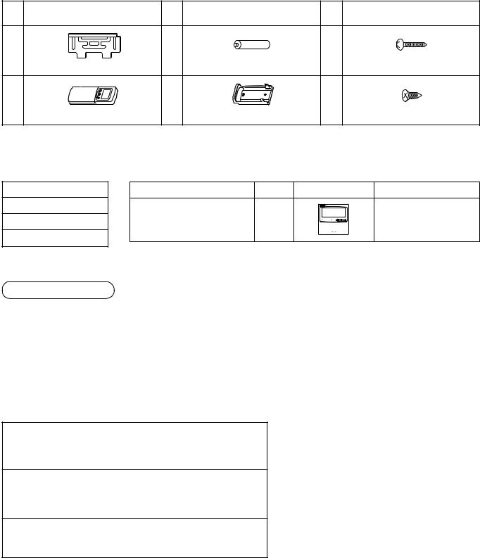
Accessory parts and parts to be procured locally
H Accessory parts
Part |
Part name (Q'ty) |
Part |
Part name (Q'ty) |
Part |
Part name (Q'ty) |
|
No. |
No. |
No. |
||||
|
|
|
||||
1 |
|
3 |
|
5 |
|
|
|
Installation plate × 1 |
|
Battery × 2 |
|
Mounting screw Ø4 × 25 l x 6 |
|
2 |
|
4 |
|
6 |
|
|
|
Wireless remote controller × 1 |
|
Remote controller holder × 1 |
|
Pan head wood screw Ø3.1 × 16 l × 2 |
<Others>
Name
Owner’ s manual
Installation manual
Paper pattern
<Separate sold parts>
Part name |
Q’ty |
Shape |
Usage |
Standard wired remote controller |
1 |
|
Model : RBC-AMT21E |
Refrigerant piping
•Piping material used for the conventional refrigerant cannot be used.
•Use copper pipe with 0.8 mm or more thickness for Ø6.4, Ø9.5.
•Flare nut and flare works are also different from those of the conventional refrigerant. Take out the flare nut attached to the indoor unit of the air conditioner, and use it.
H Parts to be procured locally
Connecting pipe (Liquid side)
(6.4mm (diam.), Nominal (diam.) 1/4” thick 0.8mm) MMK-AP0072H to MMK-AP0122H
Connecting pipe (Gas side)
(9.5mm (diam.), Nominal (diam.) 3/8” thick 0.8mm) MMK-AP0072H to MMK-AP0122H
Power supply cord
Cable 3-core 2.5mm2, in conformity with Design 60245 IEC57
1

1 PRECAUTIONS FOR SAFETY
•Ensure that all Local, National and International regulations are satisfied.
•Read this “PRECAUTIONS FOR SAFETY” carefully before Installation.
•The precautions described below include the important items regarding safety. Observe them without fail.
•After the installation work, perform a trial operation to check for any problem.
Follow the Owner’s Manual to explain how to use and maintain the unit to the customer.
•Turn off the main power supply switch (or breaker) before the unit maintenance.
•Ask the customer to keep the Installation Manual together with the Owner’s Manual.
CAUTION New Refrigerant Air Conditioner Installation
•THIS AIR CONDITIONER ADOPTS THE NEW HFC REFRIGERANT (R410A) WHICH DOES NOT DESTROY OZONE LAYER.
The characteristics of R410A refrigerant are ; easy to absorb water, oxidizing membrane or oil, and its pressure is approx. 1.6 times higher than that of refrigerant R22. Accompanied with the new refrigerant, refrigerating oil has also been changed. Therefore, during installation work, be sure that water, dust, former refrigerant, or refrigerating oil does not enter the refrigerating cycle.
To prevent charging an incorrect refrigerant and refrigerating oil, the sizes of connecting sections of charging port of the main unit and installation tools are charged from those for the conventional refrigerant.
Accordingly the exclusive tools are required for the new refrigerant (R410A).
For connecting pipes, use new and clean piping designed for R410A, and please care so that water or dust does not enter. Moreover, do not use the existing piping because there are problems with pressure-resistance force and impurity in it.
CAUTION To Disconnect the Appliance from Main Power Supply
This appliance must be connected to the main power supply by means of a switch with a contact separation of at least 3 mm.
 WARNING
•Ask an authorized dealer or qualified installation professional to install/maintain the air conditioner.
Inappropriate installation may result in water leakage, electric shock or fire.
•Turn off the main power supply switch or breaker before attempting any electrical work.
Make sure all power switches are off. Failure to do so may cause electric shock.
•Connect the connecting wire correctly.
If the connecting wire is connected in a wrong way, electric parts may be damaged.
•When moving the air conditioner for the installation into another place, be very careful not to enter any gaseous matter other than the specified refrigerant into the refrigeration cycle.
If air or any other gas is mixed in the refrigerant, the gas pressure in the refrigeration cycle becomes abnormally high and it as a result causes pipe burst and injuries on persons.
•Do not modify this unit by removing any of the safety guards or by by-passing any of the safety interlock switches.
•Exposure of unit to water or other moisture before installation may cause a short-circuit of electrical parts.
Do not store it in a wet basement or expose to rain or water.
•After unpacking the unit, examine it carefully if there are possible damage.
•Do not install in a place that might increase the vibration of the unit.
•To avoid personal injury (with sharp edges), be careful when handling parts.
•Perform installation work properly according to the Installation Manual.
Inappropriate installation may result in water leakage, electric shock or fire.
•When the air conditioner is installed in a small room, provide appropriate measures to ensure that the concentration of refrigerant leakage occur in the room does not exceed the critical level.
ENGLISH
2

1 PRECAUTIONS FOR SAFETY
•Install the air conditioner securely in a location where the base can sustain the weight adequately.
•Perform the specified installation work to guard against an earthquake.
If the air conditioner is not installed appropriately, accidents may occur due to the falling unit.
•If refrigerant gas has leaked during the installation work, ventilate the room immediately.
If the leaked refrigerant gas comes in contact with fire, noxious gas may generate.
•After the installation work, confirm that refrigerant gas does not leak.
If refrigerant gas leaks into the room and flows near a fire source, such as a cooking range, noxious gas might generate.
•Electrical work must be performed by a qualified electrician in accordance with the Installation Manual. Make sure the air conditioner uses an exclusive power supply.
An insufficient power supply capacity or inappropriate installation may cause fire.
•Use the specified wires for wiring connect the terminals securely fix. To prevent external forces applied to the terminals from affecting the terminals.
•Conform to the regulations of the local electric company when wiring the power supply.
Inappropriate grounding may cause electric shock.
•Do not install the air conditioner in a location subject to a risk of exposure to a combustible gas.
If a combustible gas leaks, and stays around the unit, a fire may occur.
2 SELECTION OF INSTALLATION PLACE
WARNING
•Install the air conditioner where there is sufficient strength to weight of the unit.
If strength is insufficient, the unit may fall down resulting in human injury.
•Perform a specified installation work to guard against an earthquake.
An incomplete installation can cause accidents by the units failing and dropping.
 CAUTION
•Do not install the air conditioner in a location subject to a risk of exposure to combustible gas.
Should the combustible gas leak and collect near the unit, fire may occur.
Upon approval of the customer, install the air conditioner in a place that satisfies the following conditions.
•Place where the unit can be installed horizontally.
•Place where a sufficient servicing space can be ensured for safe maintenance and check.
•Place where drained water will not cause any problem.
Avoid installing in the following places.
•Place exposed to air with high salt content (seaside area), or place exposed to large quantities of sulfide gas (hot spring). (Should the unit be used in these places, special protective measures are needed.)
•Place exposed to oil, vapor, oil smoke or corrosive gas.
•Place where organic solvent is used nearby.
•Place close to a machine generating high frequency.
•Place near door or window where may come to contact with the outside air of high humidity. (Dewing may be caused.)
•Place where special spray is frequently used.
•Place with poor ventilation.
3

Installation space
Reserve space required to install the indoor unit and for service work.
Keep 100mm or more for clearance between top plate of the indoor unit and the ceiling surface.
Installation diagram of Indoor and outdoor units
Before installing the wireless remote controller
•With the remote controller cover open, load the batteries supplied correctly, observeing their polarity.
2 Wireless remote controller
Cover
3 Batteries
or170mm more
Hook
Air filter
(Attach |
|
|
to |
|
|
the |
front |
panel) |
|
||
|
|
6 Pan head wood screw
2 Wireless
remote controller
4 Remote control holder
When installing the Flow Selector Unit (FS Unit), keep a space more than 300mm for wiring work.
100 mm or more
Hook
1 Installation  plate
plate
or170mm more
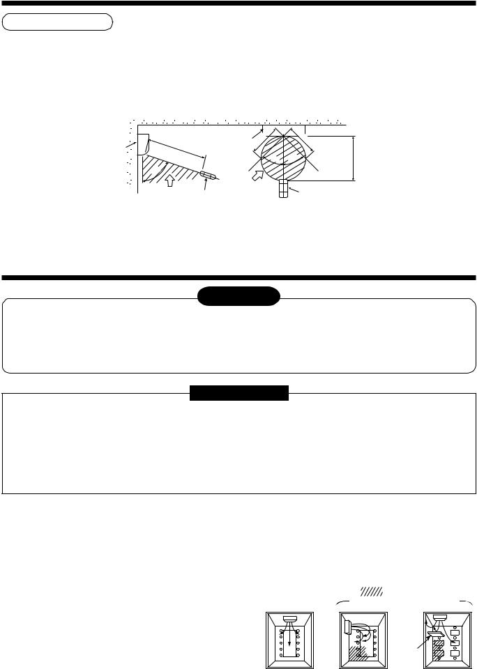
Shield pipe
For the rear left and left piping
 Wall
Wall
Insert the cushion between the indoor unit and wall, and tilt the indoor unit for better operation.
Do not allow the drain hose to get slack
Cut the piping hole sloped slightly
Make sure to run the drain hose sloped downward.
The auxiliary piping can be connected the left, rear left, rear right, right, bottom right or bottom left.
Right |
|
|
Rear right |
Rear left |
Left |
Bottom right |
Bottom left |
|
|
|
|
Installation place
•A place which provides the spaces around the indoor unit as shown in the above diagram.
•A place where there is no obstacle near the air inlet and outlet.
•A place that allows easy installation of the piping to the outdoor unit.
•A place which allows the front panel to be opened.
CAUTION
•Direct sunlight to the indoor unit’ s wireless receiver should be avoided.
•The microprocessor in the indoor unit should not be too close to RF noise sources. (For details, see the owner’ s manual.)
4
2 SELECTION OF INSTALLATION PLACE
Remote controller
•A place where there are no obstacles such as a curtain that may block the signal from the indoor unit.
•Do not install the remote controller in a place exposed to direct sunlight or close to a heating source, such as a stove.
•Keep the remote controller at least 1m apart from the nearest TV set or stereo equipment. (This is necessary to prevent image distur-bances or noise interference.)
•The location of the remote controller should be determined as shown below.
Indoor unit
(Side view) |
(Top view) |
|
|
|
7 |
|
Indoor unit |
5 |
m |
m |
|
|||
|
|
|||
|
|
|
||
|
|
|
|
|
|
|
|
|
45˚ |
75˚ |
|
|
|
|
Reception |
Reception range |
|||
Remote controller |
|
|
||
range |
|
|
|
|
|
|
|
|
|
|
|
* : Axial distance |
||
|
5 |
|
m |
45˚ |
7 m |
* |
Remote controller
3 INSTALLATION OF INDOOR UNIT
WARNING
Install the air conditioner certainly to sufficiently withstand the weight.
If the strength is insufficient, the unit may fall down resulting in human injury.
Perform a specified installation work to guard against strong wind or earthquake.
An incomplete installation can cause accidents by the units falling and dropping.
REQUIREMENT
Strictly comply with the following rules to prevent damage of the indoor units and human injury.
•Do not put a heavy article on the indoor unit. (Even units are packaged)
•Carry in the indoor unit as it is packaged if possible. If carrying in the indoor unit unpacked by necessity, be sure to use buffering cloth, etc. to not damage the unit.
•To move the indoor unit, do not apply force to the refrigerant pipe, drain pan, foamed parts, or resin parts, etc.
•Carry the package by two or more persons, and do not bundle it with PP band at positions other than specified.
Be careful to the following items when installing the unit.
•Considering air discharge direction, select an installation place where discharge air can circulate evenly in a room. Avoid to install the unit at place with “NO GOOD” mark in the right figure.
OK |
NO GOOD |
||
|
|
Bad installation place |
|
Good installation place |
|
: Not cooled well. |
|
|
|
||
Cooled well all over. |
|
|
|
|
|
|
|
Screen
5
4 CUTTING A HOLE AND MOUNTING INSTALLATION PLATE
Cutting a hole
In case of installing the refrigerant pipes from the rear:
1.Decide the hole position for piping at 100mm from
the arrow mark (  ) on the installation plate and drill a hole with Ø65mm at a slight downward slant toward outdoor side.
Pipe hole
65 mm
The center of the pipe hole is above the arrow.
100 mm
NOTE
•When drilling a wall that contains a metal lath, wire lath or metal plate, be sure to use a pipe hole brim ring sold separately.
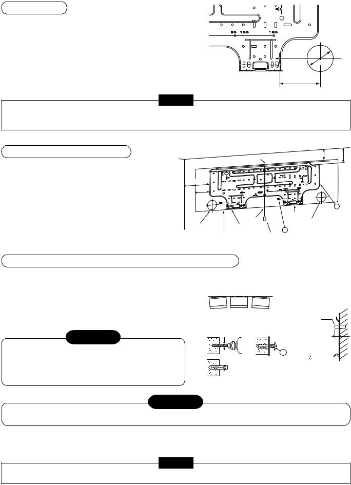
Mounting the installation plate
107 127.5
Hook
For installation of the indoor unit,
use the paper pattern in the accessory parts.
170 |
|
|
|
|
85 |
|
|
|
|
|
|
|
1 |
|
|
|
Hook |
Installation |
|
|
Thread |
plate |
||
Pipe hole |
Pipe hole |
|||
Hook |
5 Mounting screw |
|||
|
||||
|
|
|||
Indoor unit |
Weight |
|
||
When the installation plate is directly mounted on the wall
1.Securely fit the installation plate onto the wall by screwing it in the upper and lower parts to hook up the indoor unit.
2.To mount the installation plate on a concrete wall with anchor bolts, utilize the anchor bolt holes as illustrated in the above figure.
3.Install the installation plate horizontally in the wall.
CAUTION
When installing the installation plate with a mounting screw, do not use the anchor bolt hole.
Otherwise the unit may fall down and result in personal injury and property damage.
NO OK |
NO |
Anchor bolt |
GOOD |
GOOD |
|
5mm dia. hole |
|
Projection |
|
|
|
|
|
15mm or less |
|
7 |
Mounting screw |
|
|
Ø4 × 25 |
 Clip anchor (local parts)
CAUTION
Failure to firmly install the unit may result in personal injury and property damage if the unit falls.
•In case of block, brick, concrete or similar type walls, make 5mm dia. holes in the wall.
•Insert clip anchors for appropriate … mounting screws.
NOTE
• Secure four corners and lower parts of the installation plate with 4 to 6 mounting screws to install it.
6
 Loading...