


6 F 8 A 0 9 3 4
Electromagnetic Flowmeter CAPACITANCE TYPE
MODEL LF516 / LF546
INSTRUCTION MANUAL
NOTES
Before using the equipment, please read this manual carefully and understand the contents, and then use the equipment correctly.
•NEVER attempt to operate the equipment in any ways that are not described in this instruction manual.
•After reading this manual, store it with care in a place where it can be referred to whenever needed.
•Please be sure that this manual is delivered to the personnel who will use this product.

6 F 8 A 0 9 3 4
NOTICE
We thank you very much for your purchase of our LF516/LF546 CAPACITANCE TYPE series electromagnetic flowmeter.
This instruction manual describes the notes on using an electromagnetic flowmeter , installation, configuration and maintenance. It is intended for the personnel in charge of installation, operation and maintenance.
To use this product properly and safely, read this manual carefully before using this product. After reading this manual, store it in a place where it can be referred to
whenever needed.
About a PROFIBUS communication function, please read each instruction manual.
For the notes on usage, piping, installation, configuration and maintenance of the combined detector, check the model number of the combined detector and read the instruction manual of the relevant detector.
About Safety Precautions
Read the Safety Precautions described at the front carefully and understand the contents before using this product.
The “Safely symbols” used in the “Safety Precautions” are shown in a location such as in the margin to the left of the corresponding commentary in the main text.
NOTES
1.The reproduction of the contents of this Manual in any form, whether wholly or in part, is not permitted without explicit prior consent and approval.
2.The information contained in this Manual is subject to change or review without prior notice.
3.Be sure to follow all safety, operating and handling precautions described in this Manual and the regulations in force in the country in which this product is to be used.
First Edition |
Dec., 2009 |
1
6 F 8 A 0 9 3 4
SAFETY PRECAUTIONS
Safety signs and labels affixed to the product and/or described in this manual give important information for using the product safely. They help prevent damage to property and obviate hazards for
persons using the product.
Make yourself familiar with signal words and symbols used for safety signs and labels. Then read the safety precautions that follow to prevent an accident involving personal injury, death or damage to property.
Explanation of signal words
The signal word or words are used to designate a degree or level of hazard seriousness.
The signal words used for the product described in this manual are WARNING and CAUTION.
WARNING |
Indicates a potentially hazardous situation which, if not avoided, |
|
could result in death or serious injury. |
||
|
|
|
CAUTION |
Indicates a potentially hazardous situation which, if not avoided, |
|
may result in minor to moderate injuries or in property |
||
|
||
|
damage. |
|
|
|
Notes:
1“Serious injury” refers to an injury such as loss of sight, physical damage, burns (high temperature or low temperature) electric shock, bone fracture and poisoning and the after effect of the injury remains or the injury requires hospitalization or long periods of outpatient treatment.
2“Minor to moderate injuries” refers to burns, electric shocks, and so on, that do not require the injured person to be hospitalized or go to a hospital for a long period of time for medical treatment. “Property damage” includes all kinds of damage to property, equipment or materials.
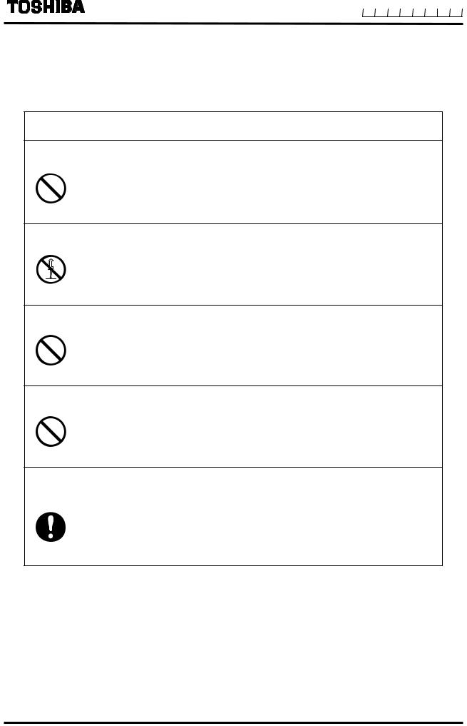
Safety symbols
The following symbols are used in safety signs and labels affixed to a product and/or in the manual for giving safety instructions.
Indicates an action that is prohibited. Simply DON’T do this action.
The prohibited action is indicated by a picture or text inside or next to the circle
Indicates an action that is mandatory. DO this action.
The mandatory action is indicated by a picture or text inside or next to the circle.
Indicates a potential hazard. The potentially hazardous situation is indicated by a picture or text inside or next to the triangle.
Color explanation
WARNING |
Background color: Yellow and Red, |
Border: Black, |
Picture display: Black |
CAUTION |
Background color: Yellow, |
Border: Black, |
Picture display: Black |
2
6 F 8 A 0 9 3 4
SAFETY PRECAUTIONS (continued)
Safety Precautions for Hazardous Locations
 WARNING
Do not disconnect while circuit is live unless location is known to be nonhazardous.
Live part of electric circuit or a high temperature department can cause explosion.
DON’T
Do not modify or disassemble the enclosure.
Strength degradation and defects of enclosure can cause explosion.
DON’T
Do not use parts of other products.
Protective performance degradation for hazardous location can cause explosion.
DON’T
Do not touch circuits until assembly of all components is over.
Protective performance degradation for hazardous location can cause explosion.
DON’T
Install per the National Electrical Code for the US (NEC, ANSI/NFPA 70) and the Canadian Electrical code for Canada (CEC, CAN/CSA-C22.1) and the drawing 3S8A2699(Refer to Appendix 2.).
Unsuitable conduit connections for hazardous location can cause explosion.
DO
3
6 F 8 A 0 9 3 4
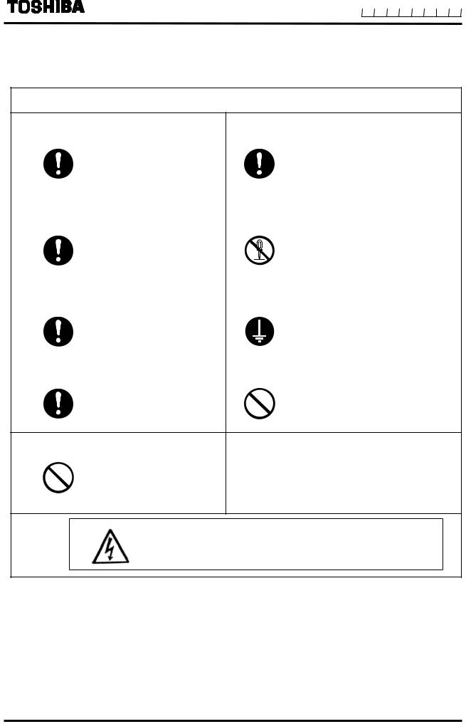
Safety Precautions for Installation and Wiring
 CAUTION
Install a switch and fuse to isolate the |
Use an appropriate device to carry and install the |
||
LF516/LF546 from mains power. |
LF516/LF546. |
||
|
Power supply from mains |
|
If this product falls to the ground, |
|
power can cause electric |
|
injury, or malfunction of or damage to |
|
shock or circuit |
|
the product, can be caused. |
DO |
break-down. |
DO |
|
|
|
||
■ Use crimped terminal lugs for the terminal |
Do not modify or disassemble LF516/LF546 |
||
board and GND terminal. |
unnecessarily. |
||
|
Loose connections can |
|
Modifying or disassembling this |
|
cause electric shock, |
|
product can cause |
|
fire from excessive |
|
electric shock, |
DO |
current or system |
DON’T |
malfunction of or damage to this |
|
malfunction. |
|
product. |
Turn off mains power before conducting |
Ground LF516/LF546 independently from power |
||
wiring work. |
|
equipment. |
(100 ohm or less ground resistance) |
|
Wiring while power is |
|
Operating this product |
|
applied can cause electric |
|
without grounding can cause |
DO |
shock. |
DO |
electric shock or malfunction. |
|
|
||
Turn off mains power before working on |
Do not work on piping and wiring with wet hands. |
||
pipes. |
|
||
|
|
|
|
|
Working on pipes while |
|
Wet hands may result in electric |
|
power is applied can cause |
|
shock. |
DO |
electric shock. |
DON’T |
|
|
|
||
Do not conduct wiring work with bare hands.
|
Remaining electric |
|
charge even if power is |
|
turned off can still cause |
DON’T |
electric shock. |
The label shown left is placed near the terminal board for power supply on the converter.
Be alert to electric shock.
4
6 F 8 A 0 9 3 4
SAFETY PRECAUTIONS (continued)
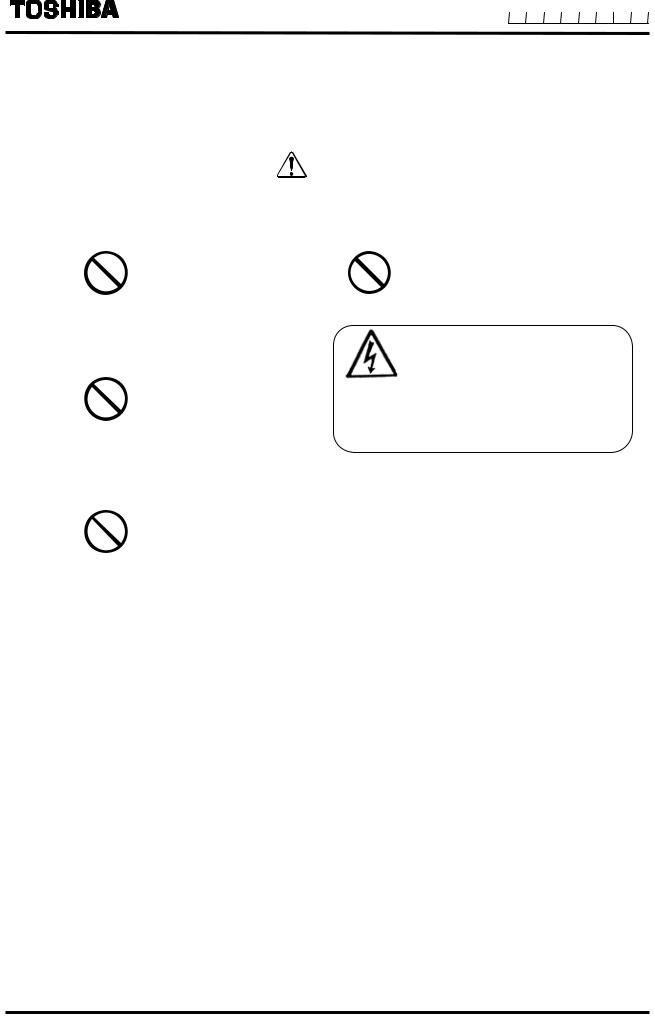
Safety Precautions for Maintenance and Inspection
|
|
CAUTION |
|
Do not touch LF516/LF546 main body |
|
Do not conduct wiring work when power is |
|
when high temperature fluid is |
|
applied. |
|
being measured. |
|
|
|
|
The fluid raises the main |
|
Wiring while power is applied can |
|
body temperature and can |
|
cause electric shock. |
DON’T |
cause burns when touched. |
|
DON’T |
|
|
|
|
Do not conduct wiring work with wet |
|
The label shown left is placed near |
|
hands. |
|
|
|
|
|
|
the terminal board for power input. |
|
Wet hands may result in |
|
(A black border and symbol on |
|
|
yellow triangle) |
|
DON’T |
electric shock. |
|
|
|
Be alert to electric shock. |
||
|
|
||
|
|
|
|
Do not use a fuse other than the one |
|
Use a rated fuse as follows: |
|
specified. |
|
|
Fuse rating: |
|
|
• 0.8A/250V for 100 to 240Vac |
|
|
Using a fuse other than the |
|
|
|
|
Dimensions: |
|
|
one specified can cause |
|
Diameter 5.2 mm × 20 mm |
DON’T |
system failure, damage or |
|
Melting time characteristic: |
malfunction. |
|
• Time Lag Fuses for 100 to 240Vac |
|
|
|
|
|
Usage limitation
This product is not manufactured for applying to a system requiring safety directly involved human life as follows. Please contact your nearest Toshiba reprehensive if there is a possibility of using this product for such use.
-Main control systems of nuclear power plants, safety protection systems in nuclear facilities or other important systems requiring safety
-Medical control systems relating to life support
Warranty and Limitation of Liability
Toshiba does not accept liability for any damage or loss, material or personal, caused as a direct or indirect result of the operation of this product in connection with, or due to, the occurrence of any event of force majeure (including fire or earthquake) or the misuse of this product, whether
intentional or accidental.
5

6 F 8 A 0 9 3 4
Handling Precautions
To obtain the optimum performance from LF516/LF546 flowmeter for years of continuous operation, observe the following precautions.
(1) Do not store or install the flowmeter in :Where there is direct sunlight.
Where excessive vibration or mechanical shock occurs.Where high temperature or high humidity conditions obtain.Where corrosive atmospheres exist.
That can be places submerged under water.
Where there is a sloped floor. To put the flowmeter temporarily on the floor, place it carefully with something, such as a block, to support it so that the flowmeter will not topple over.
Places where there is following factors.
■Factors to impede infrared switch to operate properly
Intense light such as direct sunlight and reflected sunlight by window glass or metal platePlace where brightness changes suddenly such as ON/OFF of lighting
Dense smoke or steam near the control panel
Those attached on the control panel such as rain (dew drop), snow, ice, mud and oil, and haze due to their attachment
Light reflecting object near the control panel, or reflecting object such as metal plate placed opposing to the control panel
When any of above factors is considered, take a measure for the proper operation of infrared switch such as to place a cover or to secure a space for at least a person to stand in front of the control panel.
When unable to avoid above factors, operate the EMF converter removing the factor by covering the control panel by hand so that light does not shine on it, by cleaning those attached on the control panel, or by standing in-between the reflecting object and the control panel to block the light.
(2) Wire cables correctly and securely.
Be sure to ground at the combined converter side (grounding resistance 100Ω or less). Avoid a common ground used with other equipment where earth current may flow. An independent ground is preferable
(3)Select cable paths away from electrical equipment (motors, transformers, or radio transmitters), which causes electromagnetic or electrostatic interference.
(4)The cable lead-in section must be tightened securely to keep air tightness.
NOTE : The cable connections are not provide with flowmeter. Because 1/2-14NPT screw holes are processed to this place, please prepare yourself for the cable connections.
(5)If the inside of the converter or cable terminals are wetted or humidified, it may cause insulation deterioration, which can result in fault or noise occurrence. So do not conduct wiring in the open air on rainy days.
Also, be careful not to wet down the converter even in the case of indoor wiring, and complete wiring work in a short period of time.
6

6 F 8 A 0 9 3 4
Handling Precautions (continued)
(6)Observe the following precautions when you open the converter housing cover:
•Do not open the cover in the open air unprotected against rain or wind. This can cause electric shock or cause damage to the flowmeter electronics.
•Do not open the cover under high ambient temperature or high humidity conditions or in corrosive atmospheres. This can cause deterioration of system accuracy or cause damage to the flowmeter electronics.
(7)Since a varistor is built in converter, do not conduct a withstand voltage test for the converter.
In addition, the voltage for checking the insulation of the converter must be 250VDC or lower.
(8)This product may cause interference to radio and television sets if they are used near the installation site. Use metal conduits etc. for cables to prevent this interference.
(9)Radio transmitters such as transceivers or cellular phones may cause interference to the flowmeter if they are used near the installation site. Observe the following precautions when using them:
•Close a transmitter cover before using a transceiver.
•Do not use a transceiver whose output power is more than 5 W.
•Move the antenna of a transceiver or a cellular phone at least 50 cm away from the flowmeter and signal cables when using it.
•Do not use a radio transmitter or a cellular phone near the flowmeter while it is operating online. The transmitter or cellular phone’s output impulse noise may interfere with the flowmeter.
•Do not install a radio transmitter antenna near the flowmeter and signal cables.
(10)For reasons of flowmeter failure, inappropriate parameters, unsuitable cable connections or poor installation conditions, the flowmeter may not operate properly. To
prevent any of these problems causing a system failure, it is recommended that you have preventive measures designed and installed on the flowmeter signal receiving side.
* We assume no responsibility for nonconformity caused by violation of precautions described in this manual or used in violation of the installation method and the operation method stipulated in a relevant ordinance or other regulations.
7

6 F 8 A 0 9 3 4
Table of Contents
1. |
Product Inspection and Storage............................................................................................................................ |
11 |
||
|
1.1 |
Product Inspection......................................................................................................................................... |
11 |
|
|
1.2 |
Storage.......................................................................................................................................................... |
|
11 |
2. |
Overview.................................................................................................................................................................. |
|
12 |
|
3. |
Names of Parts........................................................................................................................................................ |
|
13 |
|
|
3.1 |
Appearance OF LF516/LF546....................................................................................................................... |
13 |
|
|
3.2 |
Construction of the terminal blocks................................................................................................................ |
14 |
|
4. |
Installation............................................................................................................................................................... |
|
15 |
|
|
4.1 |
Notes on Selecting the Installation Location.................................................................................................. |
16 |
|
|
4.2 |
Mounting Procedure ...................................................................................................................................... |
17 |
|
|
|
4.2.1 |
Pipe checks.................................................................................................................................... |
17 |
|
|
4.2.2 |
Installation Procedure..................................................................................................................... |
19 |
|
4.3 |
Piping Connections ....................................................................................................................................... |
21 |
|
4.4Grounding………………………………………………………………………………………………………………24
5. Wiring |
...................................................................................................................................................................... |
|
25 |
5.1 |
Cables ........................................................................................................................................................... |
|
27 |
5.2 |
External Device Connections and Grounding ................................................................................................ |
28 |
|
5.3 |
Notes on Wiring............................................................................................................................................. |
29 |
|
5.4 |
Wiring ............................................................................................................................................................ |
|
30 |
|
5.4.1 |
Terminal Treatment of Cables ......................................................................................................... |
30 |
|
5.4.2 |
Cable Connection ............................................................................................................................ |
31 |
5.5 |
Digital I/O Connections.................................................................................................................................. |
32 |
|
6. Operation................................................................................................................................................................. |
|
33 |
|
6.1 |
Preparatory check ......................................................................................................................................... |
33 |
|
6.2 |
Zero Adjustment ............................................................................................................................................ |
34 |
|
7. LCD Display and Controls...................................................................................................................................... |
35 |
||
7.1 |
Name and Function of Each Part of LCD Display.......................................................................................... |
35 |
|
7.2 |
Display Format .............................................................................................................................................. |
38 |
|
7.3 |
Basic operations............................................................................................................................................ |
42 |
|
|
7.3.1 |
Mode Change.................................................................................................................................. |
42 |
|
7.3.2 |
Setting and Calibration .................................................................................................................... |
46 |
7.4 |
Configuration Items Selection Table.............................................................................................................. |
50 |
|
7.5 |
Password input.............................................................................................................................................. |
52 |
|
8. Parameter Settings ................................................................................................................................................. |
53 |
8

|
|
|
|
|
|
|
|
|
|
|
|
|
|
|
|
|
|
|
|
|
|
|
6 F 8 A 0 9 3 4 |
|
|
|
|
|
|
|
|
|
|
|
|
|
|
|
|
|
|
|
|
|
|
|
|
8.1 |
|
|
|
|
Parameter Setting Items................................................................................................................................ |
53 |
|||||||||||||||||
8.2 |
|
|
|
|
Check/Change of Parameters ....................................................................................................................... |
54 |
|||||||||||||||||
|
|
|
|
|
|
|
|
|
|
8.2.1 |
|
Menu Configuration Selection Screen ............................................................................................. |
54 |
||||||||||
|
|
|
|
|
|
|
|
|
|
8.2.2 |
|
Exciting Current Value..................................................................................................................... |
55 |
||||||||||
|
|
|
|
|
|
|
|
|
|
8.2.3 |
|
Meter Size ....................................................................................................................................... |
56 |
||||||||||
|
|
|
|
|
|
|
|
|
|
8.2.4 |
|
Exciting Frequency .......................................................................................................................... |
58 |
||||||||||
|
|
|
|
|
|
|
|
|
|
8.2.5 |
|
Flow Direction Setting...................................................................................................................... |
58 |
||||||||||
|
|
|
|
|
|
|
|
|
|
8.2.6 |
|
Display Setting ................................................................................................................................ |
59 |
||||||||||
|
|
|
|
|
|
|
|
|
|
8.2.7 |
|
Custom Coefficient Setting .............................................................................................................. |
63 |
||||||||||
|
|
|
|
|
|
|
|
|
|
8.2.8 |
|
Custom Unit Setting......................................................................................................................... |
64 |
||||||||||
|
|
|
|
|
|
|
|
|
|
8.2.9 |
|
Span (Range) .................................................................................................................................. |
65 |
||||||||||
|
|
|
|
|
|
|
|
|
|
8.2.10 |
|
Damping Constant........................................................................................................................... |
71 |
||||||||||
|
|
|
|
|
|
|
|
|
|
8.2.11 |
|
Rate-Of-Change Limit and Control Limit Time................................................................................. |
72 |
||||||||||
|
|
|
|
|
|
|
|
|
|
8.2.12 |
|
Low Cutoff ....................................................................................................................................... |
74 |
||||||||||
|
|
|
|
|
|
|
|
|
|
8.2.13 |
|
Display Low Cutoff........................................................................................................................... |
75 |
||||||||||
|
|
|
|
|
|
|
|
|
|
8.2.14 |
|
Still Water Zero Adjustment............................................................................................................. |
76 |
||||||||||
|
|
|
|
|
|
|
|
|
|
8.2.15 |
|
Manual Zero Adjustment ................................................................................................................. |
77 |
||||||||||
|
|
|
|
|
|
|
|
|
|
8.2.16 |
|
4-20mA Alarm Output Setting.......................................................................................................... |
78 |
||||||||||
|
|
|
|
|
|
|
|
|
|
8.2.17 |
|
Output Low Limit Setting ................................................................................................................. |
79 |
||||||||||
|
|
|
|
|
|
|
|
|
|
8.2.18 |
|
Digital Output................................................................................................................................... |
80 |
||||||||||
|
|
|
|
|
|
|
|
|
|
8.2.19 |
|
Digital Input ..................................................................................................................................... |
82 |
||||||||||
|
|
|
|
|
|
|
|
|
|
8.2.20 |
|
Count Rate (Pulse Rate), Pulse Width Setting Mode and Pulse Width ........................................... |
84 |
||||||||||
|
|
|
|
|
|
|
|
|
|
8.2.21 |
|
Preset Count ................................................................................................................................... |
87 |
||||||||||
|
|
|
|
|
|
|
|
|
|
8.2.22 |
|
Preset Mode .................................................................................................................................... |
89 |
||||||||||
|
|
|
|
|
|
|
|
|
|
8.2.23 |
|
Flow Rate High/Low Alarm and High-High/Low-Low Alarm............................................................. |
90 |
||||||||||
|
|
|
|
|
|
|
|
|
|
8.2.24 |
|
Mag-Prover-Self Diagnosis ON/OFF Setting ................................................................................... |
92 |
||||||||||
|
|
|
|
|
|
|
|
|
|
8.2.25 |
|
Fixed Value Output.......................................................................................................................... |
93 |
||||||||||
|
|
|
|
|
|
|
|
|
|
8.2.26 |
|
Password Setting............................................................................................................................. |
96 |
||||||||||
|
|
|
|
|
|
|
|
|
|
8.2.27 |
|
LCD Adjustment .............................................................................................................................. |
98 |
||||||||||
|
|
|
|
|
|
|
|
|
|
8.2.28 |
|
Switch Position Setting .................................................................................................................... |
99 |
||||||||||
|
|
|
|
|
|
|
|
|
|
8.2.29 |
|
Communication Setting ................................................................................................................. |
100 |
||||||||||
8.3Parameter initial settings list…………………………………………………………………….………………….101
9. Mag-Prover-Calibration ........................................................................................................................................ |
103 |
||
9.1 |
Calibration Items.......................................................................................................................................... |
103 |
|
9.2 |
Converter Using Mag-Prover’s Built-In Signal Source ................................................................................. |
104 |
|
|
9.2.1 |
0 % Flow Rate Calibration (Zero Calibration) ................................................................................ |
104 |
|
9.2.2 |
50 % Flow Rate Calibration ........................................................................................................... |
105 |
|
9.2.3 |
100 % Flow Rate Calibration (Span Calibration) ........................................................................... |
105 |
|
9.2.4 |
Checking the Excitation Current .................................................................................................... |
105 |
10. Functional Description......................................................................................................................................... |
106 |
|
10.1 |
Digital I/O Specifications.............................................................................................................................. |
107 |
10.2 |
Totalizer and Pulse Output .......................................................................................................................... |
108 |
10.3 |
Multi-range Function.................................................................................................................................... |
112 |
10.4 |
Flow Rate High/Low, High-High/Low-Low Alarm Output ............................................................................. |
117 |
10.5 |
Preset Count Function................................................................................................................................. |
119 |
10.6 |
Remote Zero Adjustment............................................................................................................................. |
124 |
10.7 |
Remote Selection of Fixed Value Output..................................................................................................... |
124 |
10.8 |
Converter Failure Alarm .............................................................................................................................. |
125 |
10.9 |
Multiple range high/low limit alarm function (option) .................................................................................... |
126 |
10.10 |
Custom unit function.................................................................................................................................... |
128 |
9
|
|
|
|
|
|
|
|
|
|
|
|
|
|
|
|
|
|
|
|
|
|
|
|
6 F 8 A 0 9 3 4 |
|
|
|
|
|
|
|
|
|
|
|
|
|
|
|
|
|
|
|
|
|
|
|
|
|
11. |
|
|
Communications Function .................................................................................................................................. |
131 |
||||||||||||||||||||
|
|
|
|
11.1 |
|
|
|
Connections with HHT Terminal .................................................................................................................. |
131 |
|||||||||||||||
|
|
|
|
11.2 |
|
|
|
Procedures for Communication with HHT ................................................................................................... |
132 |
|||||||||||||||
|
|
|
|
11.3 |
|
|
|
Notes on Communications .......................................................................................................................... |
133 |
|||||||||||||||
12. |
|
|
Self-Diagnosis and Alarms .................................................................................................................................. |
134 |
||||||||||||||||||||
|
|
|
|
12.1 |
|
|
|
Self-Diagnosts ............................................................................................................................................. |
134 |
|||||||||||||||
|
|
|
|
12.2 |
|
|
|
Output Status for Errors and Alarms............................................................................................................ |
137 |
|||||||||||||||
13. |
|
|
Maintenance and Troubleshooting ..................................................................................................................... |
138 |
||||||||||||||||||||
|
|
|
|
13.1 |
|
|
|
Maintenance................................................................................................................................................ |
139 |
|||||||||||||||
|
|
|
|
13.2 |
|
|
|
Troubleshooting........................................................................................................................................... |
140 |
|||||||||||||||
|
|
|
|
|
|
|
|
|
|
|
|
|
|
|
13.2.1 Flow rate is not indicated............................................................................................................... |
140 |
||||||||
|
|
|
|
|
|
|
|
|
|
|
|
|
|
|
13.2.2 Flow rate indication is not correct. ................................................................................................. |
141 |
||||||||
|
|
|
|
|
|
|
|
|
|
|
|
|
|
|
13.2.3 Flow rate indication is not stable.................................................................................................... |
142 |
||||||||
|
|
|
|
|
|
|
|
|
|
|
|
|
|
|
13.2.4 When switch operation is unable ................................................................................................... |
143 |
||||||||
14. |
|
|
Principle of Operation.......................................................................................................................................... |
144 |
||||||||||||||||||||
15. |
|
|
Specifications ....................................................................................................................................................... |
145 |
||||||||||||||||||||
|
|
|
|
15.1 |
|
|
|
Specifications .............................................................................................................................................. |
145 |
|||||||||||||||
|
|
|
|
15.2 |
|
|
|
Model Number Table ................................................................................................................................... |
149 |
|||||||||||||||
16. |
|
|
Outline Drawing.................................................................................................................................................... |
151 |
||||||||||||||||||||
Appendix 1 |
..................................................................................................................................................................... |
|
|
|
|
|
|
|
|
152 |
||||||||||||||
Appendix 2 |
.................................................................................................................................................................... |
|
|
|
|
|
|
|
|
154 |
||||||||||||||
10

6 F 8 A 0 9 3 4
1. Product Inspection and Storage
1.1 Product Inspection
LF516/LF546 electromagnetic flowmeter is shipped in a cardboard container filled with shock-absorbing materials. Open the package carefully and check as follows:
Make sure the following items are included in the package.
Inspect the flowmeter for indications of damage that may have occurred during shipment.
Make sure the type and specifications of the flowmeter are in accordance with the ordered specifications.
If you cannot find the items listed above or any problem exists, contact your nearest Toshiba representative.
1.2 Storage
To store the electromagnetic flowmeter after opening the package, select a storing place as follows and keep it under the conditions described below:
 CAUTION
(1)Avoid places where there is direct sunlight, rain or wind.
(2)Store the product in a well-ventilated place. Avoid places of extremely high humidity or extremely high or low temperature. The following environment is recommended:
•Humidity range: 10 to 90% RH (no condensation)
•Storage temperature: –25 to +65° C
(3)Avoid places where vibrations or mechanical shock occur.
(4)If it leaves the cover of converter open while being stored, gradual deterioration of circuit isolation can be caused. And then don’t open the cover until it is connected with wires.
(5)To put the flowmeter temporarily on the floor, place it carefully with something, such as stopper, to support it so that the flowmeter will not topple over.
11

6 F 8 A 0 9 3 4
2. Overview
LF516/LF546 electromagnetic flowmeter can be use in the following hazardous (classified) locations.
Class , Division 2, Groups A, B, C and D,
Class , Division 2, Groups E, F and G
Class
This product is electromagnetic flowmeter that measure the volumetric flow rate of conductive fluid using Faraday's law of electromagnetic induction.
The device consists of two units: the detector, through which the fluid to be measured flows, and the converter, which receives the electromotive force signals from the detector, then converts the signals into the 4–20 mA dc signal.
Features
With a linear relationship between the flow rate and output signal, the electromagnetic flowmeter is featured as an easy-to-read indicator. In addition to this feature, it has the following outstanding features:
(1)Low electric conductivity fluid (Electric conductivity 0.01μS/cm or more) can be measured
(2)Wide flow velocity range setting, such as a flow velocity range of 0~0.5 and 0~10m/s, is achieved.
(3)This flowmeter can be used to measure fluid even if it contains high concentration of slurryCeramics is used for the detector pipe as standard.
The unique Noise-Sentry filter circuit and its advanced Arithmetic Logic Unit (ALU) enables you to obtain a stable output.
(4)Full graphic electronically rotatable LCD that enables display of a large amount of information
1.With a large amount of a maximum of 9 characters x 7 lines, you can easily check various displays including bar graphs and alarm indications.
2.The backlight allows you to read the indicator easily.
(5)Use of infrared switches
•Use of infrared switches allows you to perform various operations, without opening the converter housing cover.
(6)Intelligent functions
•The widely used HART protocol*1 communications system is used as a standard feature.
•This product supports PROFIBUS*2 communication by option.
* 1 HART protocol: “HART” stands for Highway Addressable Remote Transducer and is a communication protocol recommended by HCF (HART communication Foundation) for industrial sensors.
* 2 PROFIBUS: PROFIBUS, which stands for PROCESS FIELDBUS, is a kind of field bus that is approved by nternational standard IEC61158. The electromagnetic flowmeter supports PRFIBUS PA for process automation.
12
6 F 8 A 0 9 3 4
3. Names of Parts
IMPORTANT
The cable connections are not provided in the conduit port of this apparatus.
Please prepare yourself for the cable connections, which could be used in Division2 hazardous locations.
3.1 Appearance of LF516/LF546
Converter
Terminal block cover
Display section
For power cable
Control key (Control panel)
|
|
|
|
|
|
|
|
|
|
|
|
|
|
|
|
|
|
|
|
|
|
|
|
|
|
|
|
|
|
|
|
|
|
|
|
|
|
|
|
|
|
|
|
|
|
|
|
|
|
|
|
|
|
|
|
|
|
|
|
|
|
|
|
|
|
|
|
|
|
|
|
|
|
|
|
|
|
|
|
|
|
|
|
|
|
|
|
|
|
|
For |
current output cable |
||||||||||||
|
|
|
|
|
|
|
|
|
|
|
|
|
|
|
|
|
|
|
|
|
|
|
|
|
|
|
|
|
Arrow nameplate |
Ground terminal |
|
|
|
|
|
|
|
|
|
|
||||
|
|
Raised portion |
|
|||||||||||
|
|
|
|
|
||||||||||
|
|
|
||||||||||||
|
|
|
|
|
|
|
|
|
|
|
|
|
|
|
Detector
Figure 3.1.1 Appearance of LF516/LF546
13
6 F 8 A 0 9 3 4
3.2 Construction of the terminal blocks
Terminal Block Construction of LF546 Converter
When you remove the terminal block cover shown in the figure "Appearance of LF516/LF546", you can see the converter terminal block as shown below.
|
Internal grounding |
Power supply terminal |
terminal |
Fuse
Digital output
terminal |
|
0.8A(T)/250V |
External grounding terminal
Digital input terminal
Current output terminal or
PROFIBUS* terminal Signal common *Option
termnal
CAUTION
The label shown left is placed near the terminal board for power supply to this equipment.
Be alert to electric shock.
Figure 3.2 Terminal Block Construction of LF546
14
6 F 8 A 0 9 3 4
4. Installation
Safety Precautions for Installation
 WARNING
Do not activate live circuits under environment of explosive atmospheres.
Live part of electric circuit or a high temperature department can cause explosion.
DON’T
Do not use parts of other products.
Protective performance degradation for hazardous location can cause explosion.
DON’T
Do not activate circuits While assembly of all components is not over.
Protective performance degradation for hazardous location can cause explosion.
DON’T
Install per the National Electrical Code for the US (NEC, ANSI/NFPA 70) and the Canadian Electrical code for Canada (CEC, CAN/CSA-C22.1) and the drawing 3S8A2699 (Refer to Appendix 2.).
Unsuitable conduit connections for hazardous location can cause explosion.
DO
|
|
CAUTION |
||
Turn off mains power before working |
Use an appropriate device to carry and install |
|||
on pipes. |
|
the LF516/LF546. |
||
|
Working on pipes while |
|
If his product falls to the ground, |
|
|
|
injury, or |
||
|
power is applied can cause |
|
||
|
|
malfunction of or damage to the |
||
DO |
electric shock. |
DO |
||
product, can be caused. |
||||
|
|
|||
Do not modify or disassemble the |
Ground the LF516/LF546 |
|||
unnecessarily. |
independently from power equipment. |
|||
|
Modifying or |
(100 ohm or less ground resistance) |
||
|
|
|
||
|
disassembling this product |
|
Operating this product without |
|
|
can cause electric shock, |
|
grounding can cause electric shock |
|
DON’T |
malfunction or damage to |
DO |
or malfunction. |
|
|
this product. |
|
|
|
Do not work on piping and wiring |
|
|
||
with wet hands. |
|
The label shown left is placed |
||
|
Wet hands may result in |
|
||
|
electric shock |
|
near the terminal board for |
|
|
|
power supply to the converter. |
||
DON’T |
|
|
||
|
|
Be alert to electric shock |
||
15

6 F 8 A 0 9 3 4
4.1 Notes on Selecting the Installation Location
This product is designed for the following environment.
Indoor and outdoor installation |
Ambient temperature: 10 to 50 |
Altitude:Up to 2000m |
Humidity range:10 to 90%(no condensation) |
Regulation of power voltage:±10% |
|
Pollution degree 2 |
Structure:IP67 and NEMA 4X |
Do not store or install the flowmeter in :
1.Places within the immediate proximity of equipment producing electrical interference (such as motors, transformers, radio transmitters, electrolytic cells, or other equipment causing electromagnetic or electrostatic interference).
2.Where there is direct sunlight.
3.Where excessive vibration or mechanical shock occurs.
4.Where high temperature or high humidity conditions obtain.
5.Where corrosive atmospheres exist.
6.That can be submerged under water.
7.Where there is a sloped floor. To put the flowmeter temporarily on the floor, place it carefully with something, such as a block, to support it so that the flowmeter will not topple over.
8.Places of too great an elevation or constricted areas where clearance for installation or maintenance work is not provided.
9.Avoid places where fluid runs in a pulsating form.
10.Design piping so that the detector pipe is always filled with fluid, whether the fluid is flowing or not.
11.The detector has no adjustable piping mechanism. Install an adjustable short pipe where needed.
12.Chemical injections should be conducted on the downstream side of the flowmeter.
13.Places where there is following factors.
Factors to impede infrared switch to operate properly
Intense light such as direct sunlight and reflected sunlight by window glass or metal platePlace where brightness changes suddenly such as lighting being turned ON/OFFDense smoke or steam near the control panel
Those attached on the control panel such as rain (dew drop), snow, ice, mud and oil, and haze due to their attachment
Light reflecting object near the control panel, or reflecting object such as metal plate placed opposing to the control panel
When any of above factors is considered, take a measure for the proper operation of infrared switch such as to place a cover or to secure a space for at least a person to stand in front of the control panel.
When unable to avoid above factors, operate the EMF converter removing the factor by covering the control panel by hand so that light does not shine on it, by cleaning those attached on the control panel, or by standing in-between the reflecting object and the control panel to block the light.
16
6 F 8 A 0 9 3 4
4.2Mounting Procedure
1.Avoid places within the immediate proximity of equipment producing electrical interference (such as motors, transformers, radio transmitters, electrolytic cells, or other equipment causing electromagnetic or electrostatic interference).
2.Avoid places where excessive pipe vibration occurs.
3.Avoid places where fluid runs in a pulsating form.
4.Avoid places where there is direct sunlight. If this is unavoidable, use an appropriate shade
5.Avoid places where corrosive atmospheres or high humidity conditions obtain.
6.Avoid places of too great an elevation or constricted areas where clearance for installation or maintenance work is not provided.
7.Design piping so that the detector pipe is always filled with fluid, whether the fluid is flowingor not.
8.The detector has no adjustable piping mechanism. Install an adjustable short pipe where needed.
9.Chemical injections should be conducted on the downstream side of the flowmeter.
4.2.1 Pipe checks
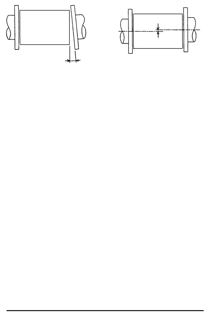
(1)Before installing pipes, check for any leaning or misplacement (or eccentricity) as illustrated in Figure 4.1. An attempt to unreasonably connecting pipes that are inclined may lead to a detector breakdown or fluid leakage. Connecting pipes in an eccentric state may also cause local wears and tears of linings and
grounding rings, as well as measurement errors.
Before installing pipes, make sure to flash the interior of the pipes to remove deposited matters.
Eccentricity
Inclination
(a) Pipe leaning |
(b) Pipe axis misplacement (or eccentricity) |
Figure 4.1 Pipe leaning and axis misplacement
17
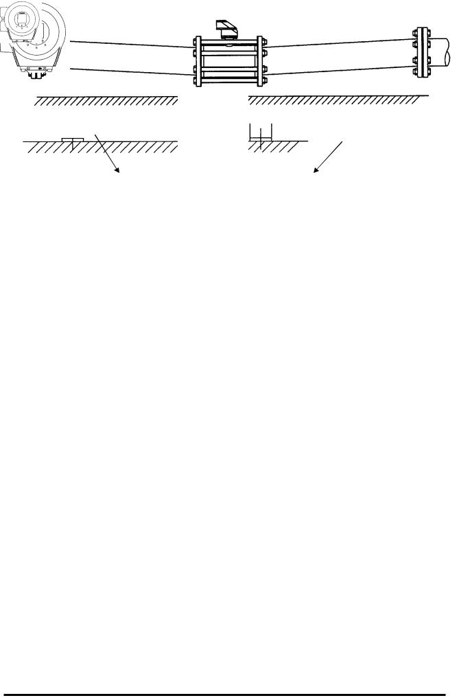
6 F 8 A 0 9 3 4
(2) Preventing an Empty Pipe Condition
Fix the relevant pipes installed on both sides of the detector by attach fittings, etc. to support the pipe. By supporting the pipes, not only the pipe vibration is reduced but also the damage to the pipes by the electromagnetic flowmeter's weight and the fluid mass (see Figures 4.2 and 4.3).
Pipe support fittings |
Pipe support fittings |
|
Figure 4.2 Example of Pipe Fixing Procedure
Figure 4.3 Model Diagram of Unsupported Pipes
18
6 F 8 A 0 9 3 4
4.2.2 Installation Procedure
To mount the LF516/LF546, place it between the upstream and downstream pipe flanges and tighten it with flange bolts and nuts. See Figure 4.4 and follow the procedure below:
1.Insert two lower mounting bolts through the clearance holes in the upstream (or downstream) pipe flange.
2.Install a packing next to the upstream (or downstream) flange face and the other packing next to the downstream (or upstream) pipe flange. The two mounting bolts can now be guided through the clearance holes in the downstream packing and flange.
3.Place the LF516/LF546 flowmeter detector between the two flange packings, with the flowmeter detector body above the two bolts. The flowmeter must be oriented in accordance with the
flow direction arrow.
4. .Install the two upper mounting bolts through the clearance holes in the upstream and downstream packings and flanges. Then install the remaining mounting bolts depending on the flange pattern used.
5.Thread nuts on both ends of the 4 (or more) mounting bolts, finger tight. (See Table 4.1 Bolt length and tightening torque)
6.While centering the flowmeter with the longitudinal axis of the pipeline, tighten the nuts with a wrench diagonally across in even increments. (See Table 4.1 Bolt length and tightening torque)
Note that the flowmeter detector pipe axis must be aligned with the pipeline axis on both upstream and downstream sides. This is essential to have stable characteristics of flow measurement (especially for flowmeters with meter sizes of 50 mm or less).
IMPORTANT
When high-temperature fluid is being measured, radiant heat from the detector pipe surface and adjoining pipes may cause the ambient temperature of the converter to go above 50 °C. If the ambient temperature goes above 50° C, try to lower the temperature by measures such as wrapping heat-insulating materials over the detector pipe and adjoining pipes.
Converter
|
|
|
|
|
|
|
|
|
|
|
|
|
|
|
|
|
|
|
|
|
|
|
|
|
|
|
|
|
|
|
|
|
|
Detector |
|
|
|
|
|
||
|
|
|
|
|
|
|
|
|
|
|
|
|
|
|
|
|
|
|||
|
|
|
|
|
|
|
|
|
|
|
|
|
|
|
|
|
|
|
|
|
|
|
|
|
|
|
|
|
|
|
|
|
|
|
|
|
|
|
|
|
|
|
|
|
|
|
|
|
|
|
|
|
|
|
|
|
|
|
|
|
|
|
|
|
|
|
Packing |
|
|
|
|
|
|
|
|
|
|
|
|
|
|||
|
|
|
|
|
|
|
|
|
|
|
|
|
|
|
|
|
||||
|
|
|
|
|
|
|
|
|
Packing |
|
|
|
|
|||||||
|
|
|
|
|
|
|
|
|
|
|
|
|
|
|
|
|
||||
|
|
|
|
|
|
|
|
|
|
|
|
|
|
|
|
|
|
|
|
|
|
|
|
|
|
|
|
|
|
|
|
|
|
|
|
|
|
|
|||
|
|
|
|
|
|
|
|
|
|
|
|
|
|
|
Upper mounting |
bolts |
||||
|
|
|
|
|
|
|
|
|
|
|
|
|
|
|
|
|
|
|
|
|
Flow direction |
|
|
|
|
|
|
|
|
|
|
|
|
|
|
Lower mounting |
bolts |
||||
|
|
|
|
|
|
|
|
|
|
|
|
|
|
|
||||||
|
|
|
|
|
|
|
|
|
|
|
|
|
|
|
|
|
|
|
||
|
|
|
|
|
|
|
|
|
|
|
|
|
|
|
|
|
|
|
|
|
|
Upstream flange |
|
|
|
|
|
|
|
|
Downstream flange |
||||||||||
|
|
|
|
|
|
|
|
|
|
|
|
|
|
|
|
|
|
|
|
|
|
|
|
|
|
|
|
|
|
|
|
|
|
|
|
|
|
|
|
|
|
Figure 4.4 LF516/LF546 flowmeter piping connections
19
6 F 8 A 0 9 3 4
Table 4.1 Bolt length and Nut tightening torque
|
|
|
ANSI class 150 |
|
|
|
ANSI class 300 |
|
||||
Meter size |
Through Bolts |
|
Tightening |
|
Through Bolts |
|
Tightening |
|||||
P.C.S |
Dia- |
Length |
|
torque |
|
P.C.S |
Dia- |
Length |
|
torque |
||
|
|
|
|
|
||||||||
|
|
meter |
[mm] |
|
[N m] |
|
meter |
[mm] |
|
[N m] |
||
|
|
|
|
|
|
|
|
|
|
|
|
|
15mm |
1/2” |
4 |
1/2” |
150 |
|
12 to 15 |
4 |
1/2” |
155 |
|
25 to 31 |
|
25mm |
1” |
4 |
1/2” |
170 |
|
21 to 26 |
4 |
5/8” |
180 |
|
53 to 66 |
|
40mm |
1 1/2” |
4 |
1/2” |
195 |
|
32 to 40 |
4 |
3/4” |
215 |
|
96 to 120 |
|
50mm |
2” |
4 |
5/8” |
215 |
|
52 to 65 |
8 |
5/8” |
220 |
|
52 to 65 |
|
80mm |
3” |
4 |
5/8” |
225 |
|
71 to 88 |
8 |
3/4” |
240 |
|
85 to 106 |
|
100mm |
4” |
8 |
5/8” |
235 |
|
52 to 65 |
8 |
3/4” |
255 |
|
125 to 156 |
|
|
|
DIN/BS 10, DIN/BS 16 |
|
|
JIS 10K |
|
|||
Meter size |
Through Bolts |
Tightening |
Through Bolts |
Tightening |
|||||
P.C.S |
Dia- |
Length |
torque |
P.C.S |
Dia- |
|
Length |
torque |
|
|
|
||||||||
|
meter |
[mm] |
[N m] |
meter |
|
[mm] |
[N m] |
||
|
|
|
|
|
|
|
|
|
|
15mm |
4 |
M12 |
150 |
16 to 19 |
4 |
M12 |
|
150 |
10 to 13 |
25mm |
4 |
M12 |
165 |
27 to 34 |
4 |
M16 |
|
170 |
22 to 28 |
40mm |
4 |
M16 |
190 |
58 to 72 |
4 |
M16 |
|
190 |
32 to 40 |
50mm |
4 |
M16 |
205 |
78 to 98 |
4 |
M16 |
|
200 |
43 to 53 |
80mm |
8 |
M16 |
210 |
54 to 67 |
8 |
M16 |
|
210 |
27 to 34 |
100mm |
8 |
M16 |
220 |
79 to 99 |
8 |
M16 |
|
215 |
37 to 46 |
20
6 F 8 A 0 9 3 4
4.3Piping Connections
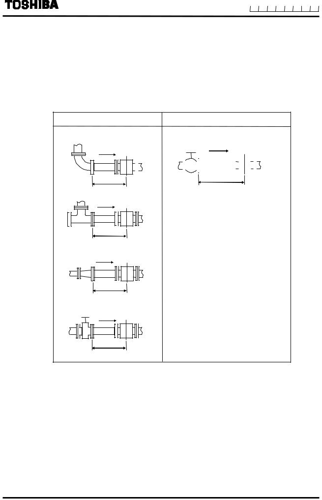
(1)Required Pipe Length
If various joints are used upstream of the detector outlet, the straight pipe length as shown in Table 4.2 is required.
Table 4.2 Required straight pipe length on the upstream side
|
L=5D |
|
|
|
|
|
|
|
|
L=10D |
|||||||||
(1) 90°bent |
|
|
(5) Other valves (not fully opened) |
||||||||||||||||
|
|
|
|
|
|
|
|
|
|
|
|
|
|
|
|
|
|
|
|
|
|
|
|
|
|
|
|
|
|
|
|
|
|
|
|
|
|
|
|
|
|
|
|
|
|
|
|
|
|
|
|
|
|
|
|
|
|
|
|
|
|
|
|
|
|
|
|
|
|
|
|
|
|
|
|
|
|
|
|
L L
(2) Tee
L
(3) Diffuser
L
(4) Fully opened sluice valve
L
L: Required straight pipe length—straight pipe length plus half length of the detector. D: Nominal bore size (diameter)
NOTES
The length of a reducer, if connected, can be counted as a part of the straight pipe length.
No straight pipe length is needed on the downstream side. If a butterfly valve is installed downstream of the detector, do not let the valve plate protrude into the pipe of the detector
21
6 F 8 A 0 9 3 4
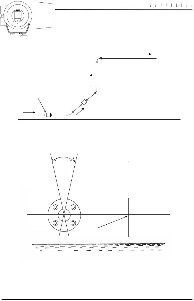
(2) Pipe Orientation
The detector may be installed in horizontal, vertical or sloping pipe runs as shown in Figure 4.5. However, except for horizontal installation, fluid should flow from lower to upper directions. See Figure 4.5.
|
|
|
|
|
|
Flow direction |
||
|
|
|
|
|
|
|
|
|
|
|
|
|
|
|
(b) |
||
|
|
|
|
|
|
|||
|
|
|
|
|
|
(a) Horizontal pipe installation |
||
|
|
|
|
|
|
(b) Vertical pipe installation |
||
Detector |
|
|
|
|
|
(c) Sloping pipe installation |
||
(c)
(a)
Ground surface
Figure 4.5 Detector Piping Orientation
The electrodes should be positioned horizontally against the ground surface in any piping installation. See Figure 4.6.
Don’t rotate.
Detector
Ground surface
Figure 4.6 Installation position of the detector
22
6 F 8 A 0 9 3 4
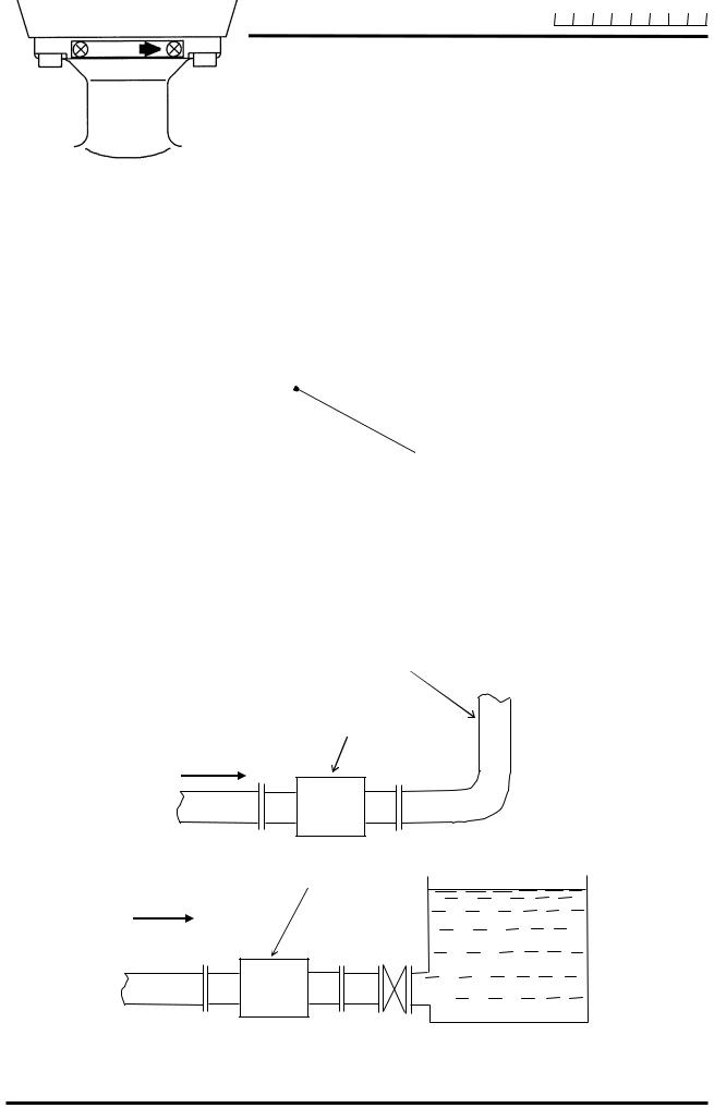
(3) Flow Direction
Install the detector in accordance with the flow direction arrow on the detector. See Figure 4.7. If the actual flow runs opposite to the specified flow direction, the following display and output appears.
For single range measurement, |
|
|
LCD display: |
Instantaneous flow rate ------------- |
indicates negative values, |
|
Totalized flow ------------------------ |
no counts added. |
Outut: |
Current output ------------------------ |
4.0mA output, |
|
Pulse output --------------------------- |
No pulses |
For bidirectional range measurement, the flow in opposite direction results in a positive output value. See 10.3, “Multi-range Functions.”
Flow direction arrow
Figure 4.7 Flow direction arrow on the detector
(4) Preventing an Empty Pipe Condition
Design an upright pipe run (Figure 4.8) or sufficient head pressure (Fig. 4.9) at the downstream detector outlet if there is a possibility of the detector pipe becoming emptied.
Upright pipe run
Detector
Figure 4.8 Detector with an upright pipe run at downstream outlet
Detector
Figure 4.9 Detector with sufficient head pressure at downstream outlet
23
6 F 8 A 0 9 3 4
4.4 Grounding
 CAUTION
Do not wire cables and replace parts when power is supplied.
|
Wiring work and replacing |
|
parts in the power-on state |
DON’T |
may cause electric shock. |
Do not work on piping and wiring with wet hands.
Wet hands may result in electric shock.
DON’T
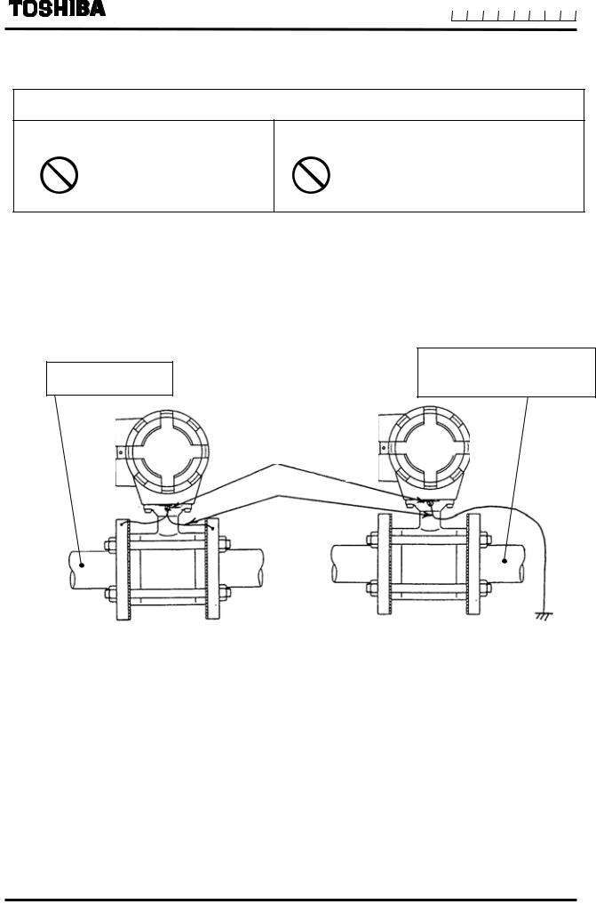
Ground as shown in Figure 4.10. Make the grounding wire as short as possible. Use grounding wire material of IV wire 5.5mm2 or more. Do not share a grounding wire with other instruments where grounding current may flow. (An independent grounding is preferable.)
Conductive material pipe
Example: Metal, etc.
• If the piping material is conductive, connect the grounding wires to the both ends of the piping flange.
Piping of non-conductive material Example: Resin or metal piping whose inside is resin-lined, etc.
Grounding terminal
Grounding wire
grounding resistance 100Ωormore
• If the piping material is non-conductive, perform grounding (grounding resistance 100Ω or less).
Figure 4.10 Grounding the LF516/LF546 Type
24
6 F 8 A 0 9 3 4
5. Wiring
Notes on wiring
 WARNING
DO NOT DISCONNECT WHILE CIRCUIT IS LIVE UNLESS LOCATION IS KNOWN TO BE NONHAZARDOUS.
Live part of electric circuit or a high temperature department can cause explosion.
DON’T
Do not activate circuits while assembly of all components is not over.
Protective performance degradation for hazardous location can cause explosion.
DON’T
Install per the National Electrical Code for the US (NEC, ANSI/NFPA 70) and the Canadian Electrical code for Canada (CEC, CAN/CSA-C22.1) and the drawing 3S8A2699 (Refer to Appendix 2.).
Unsuitable conduit connections for hazardous location can cause explosion.
DO
25
6 F 8 A 0 9 3 4
CAUTION
Install a switch and fuse to isolate the |
Turn off mains power before conducting |
|||
LF516/LF546 from mains power. |
wiring work. |
|||
|
|
Power supply from mains |
|
Wiring while power is applied |
|
|
power can cause electric shock |
|
can cause electric shock. |
DO |
or circuit break-down. |
DO |
|
|
|
|
|||
Do not work on piping and wiring with |
Ground the LF516/LF546 |
|||
wet hands. |
|
independently from power equipment. |
||
|
|
|
(100 ohm or less ground resistance) |
|
|
|
Wet hands may result in |
|
Operating this product without |
DON’T |
electric shock |
DO |
grounding can cause electric |
|
|
shock or malfunction. |
|||
Do not conduct wiring work with bare |
For the power supply wiring and grounding |
|||
hands. |
|
wiring, use crimping terminals with |
||
|
|
|
insulated sleeve. |
|
|
|
Remaining electric charge |
|
There is a risk of electric shock |
|
|
even if power is turned off can |
|
due to drop-off or loosing, and a |
DON’T |
still cause electric shock. |
DO |
risk of fire and equipment |
|
|
trouble due to heat generation. |
|||
|
|
|
|
|
Do not modify or disassemble the |
|
|
||
LF516/LF546 unnecessarily. |
|
The label shown left is |
||
|
|
Modifying or |
|
|
|
|
|
placed near the power |
|
|
|
disassembling this product can |
|
|
|
|
|
supply terminal on the |
|
|
|
cause electric shock, |
|
converter. |
DON’T |
malfunction of or damage to |
|
Be alert to electric shock. |
|
this product. |
|
|
||
|
|
|
|
|
|
|
|
|
|
Flowmeter accuracy may be affected by the way wiring is executed. Proceed with correct wiring taking the precautions in following pages.
26

6 F 8 A 0 9 3 4
 CAUTION
(1)Select the cable run location so they are away from electrical equipment (motors, transformers, or radio transmitters) which causes electromagnetic or electrostatic interference.
(2)Deterioration of flowmeter circuit insulation occurs if the converter interior or cable ends get wet or humidified. This in turn causes malfunction of flowmeter or noise problems. Avoid a rainy day if the flowmeter is to be installed outdoors. Even indoors, prevent water from splashing over the flowmeter. Try to finish the wiring as quickly as possible
(3)The converter has a surge arrestor/protector installed inside. Therefore, do not conduct a withstand voltage test for the converter. To check the insulation of the converter, use a voltage of 250Vdc or less.
(4)After wiring, be sure to install the terminal block protection cover.
5.1Cables
Use the kind of cables shown in Table 5.1 to wire the converter.
Table 5.1 Installation Cables
|
|
Nominal |
Finished |
|
|
Name |
Cable name |
cross-sectional |
outer |
Description |
|
|
|
area |
diameter |
|
|
|
|
|
|
|
|
|
|
|
|
CVV JIS C |
|
Power cable |
3-core vinyl sheathed cable or 2-core vinyl |
2 mm² |
11~13mm |
3401,IEC60695,IEC607 |
|
sheathed cable |
54,IEC60227,IEC60245 |
||||
|
|
|
|||
|
|
|
|
or equivalent |
|
|
The number of conductors the cable contains |
differs depending on the |
|
||
Output signal |
specification of the output signal cable. |
|
|
CVV-S JIS -258-C or |
|
Use a shielded cable of finished outer diameter 11 to 13mm and nominal |
|||||
cable |
equivalent |
||||
cross-sectional area 1.25mm2. |
|
|
|||
|
|
|
|
||
|
|
|
|
|
|
27

6 F 8 A 0 9 3 4
5.2 External Device Connections and Grounding
The terminal board connections of LF516/LF546 Flowmeter are shown in Figure 5.1. Proceed with wiring as described in Section 5.4, “Wiring Procedure.”
Ground terminal
IV wire
5.5mm2 or more
(100 ohm or less ground resistance)
NOTE:
• When 3-core power cabel is used, do not ground from the external grounding terminal.(Perform grouding at the receving side only).
•Only when a 2-core power cable is used, perform grounding from the external grounding terminal.
Power cable (CVV)
* For a 2-core cable, L1 and L2 only.
[Instrumentation panel: Customer] (Receiving side)


 Power supply
Wiring breaker (double-pole/single-throw)
(100 ohm or less ground resistance)
Converter unit
Output signal cable (CVV-S)
Current output (4-20mAdc) or PROFIBUS
Digital output 1
Common for DI/DO
Digital output 2
Digital input (20 to 30 Vdc)
NOTE:
To avoid 2-point grounding, ground the shield of the output cable basically at the receiving side.
(100 ohm or less ground resistance)
Figure 5.1 External Wiring Schematic Diagram
*Use a heavy copper braid or wire (cross-sectional area 5.5 mm2 minimum) to ground the terminal and make it as short as possible as shown in Figure 5.1 for grounding.
Also, Avoid a common ground where earth current may flow. (An independent ground is preferable.)
*The converter has no power switch. Install the power switch at the system side. Be sure to use a double-pole/single-throw (both disconnection) wiring breaker.
28

6 F 8 A 0 9 3 4
5.3 Notes on Wiring
Notes on Instrumentation-Converter Wiring
•To avoid 2-point grounding, ground the shield of output cable basically at the receiving side.
•Use a grounding wire of IV wire 5.5mm2 or more. The size of the external grounding terminal screws is M4. Do not share a grounding wire with other instruments where grounding current may flow. (An independent grounding is preferable.)
•Power cable
When a 3-core cable is used: Ground with the FG terminal.
When a 2-core cable is used: Use an external grounding terminal and make the cable as short as possible.
29
 Loading...