


 Loading...
E6581741h
TOSVERT VF-MB1/S15
EtherNet/IP™ - Modbus® TCP option Function Manual
IPE002Z
NOTICE
1.Read this manual before installing or operating. Keep this instruction manual on hand of the end user, and make use of this manual in maintenance and inspection.
2.All information contained in this manual will be changed without notice. Please contact your Toshiba distributor to confirm the latest information.
E6581741
Introduction
Thank you for purchasing the “EtherNet/IP™ - Modbus® TCP option (IPE002Z)” for TOSVERT VF-MB1/S15 inverter. Before using EtherNet/IP™ - Modbus® TCP module, carefully read this function manual in order to completely and correctly utilize its excellent performance.
This option needs the option adaptor to connect VF-S15 which type form is SBP009Z. Please match here and buy it when SBP009Z is not at hand yet.
After reading this function manual, please keep it handy for future reference.
For details of its general handling, see an instruction manual attached with the option unit.
-TOSVERT VF-MB1 Instruction Manual ························································· E6581697
-TOSVERT VF-S15 Instruction Manual ·························································· E6581611
-TOSVERT VF-MB1/S15 communication option Precautions Manual··········· E6581739
-TOSVERT VF-MB1 Communication Function Instruction Manual················ E6581726
-TOSVERT VF-S15 Communication Function Instruction Manual················· E6581913
EtherNet/IP™ is a trademark of ControlNet International, Ltd.
Modbus® TCP is a registered trademark of AEG Schneider Automation International S.A.S.

 Handling in general
|
|
|
Warning |
|
|
|
Do not connect or disconnect a network cable while the Inverter power is on. |
|
Prohibited |
It may lead to electric shocks or fire. |
|
|
|
||
|
|
|
See the instruction manual attached with the option unit for cautions the handling. |
|
Mandatory |
Otherwise, it may lead to electric shocks, fire, injuries or damage to product. |
|
|
|
||
|
|
Network control |
|
|
|
||
|
|
||
|
|
|
Warning |
|
|
|
Do not send the value out of the valid range to objects and attributes. |
|
Prohibited |
Otherwise, the motor may suddenly start/stop and that may result in injuries. |
|
|
|
||
|
|
|
Use an additional safety device with your system to prevent a serious accident due to the |
|
Mandatory |
network malfunctions. Usage without an additional safety device may cause an accident. |
|
|
|
||
|
|
|
Caution |
|
Set up “Communication error trip function (see below)” to stop the Inverter when the |
|
|
option unit is deactivated by an unusual event such as tripping, an operating error, |
|
|
power outage, failure, etc. |
|
|
- Network Time-Out, Inverter operation at disconnection, Preset speed operation |
|
|
selection |
|
Mandatory |
(Refer to "3.2.3 Network error detection (c100 - c103, c523)" for details) |
|
Deactivated the option module may cause an accident, if the “Communication error trip |
||
|
||
|
function” is not properly set up. |
 Make sure that the operation signals are STOP before resetting Inverter’s fault. The motor may suddenly start and that may result in injuries.

 Notes on operation
Notes
 When the control power is shut off by the instantaneous power failure, communication will be unavailable for a while.
 The Life of EEPROM is approximately 100,000 times. Avoid writing a command more than 100,000 times to the same parameter of the Inverter and the option module.
--11--

|
|
|
|
E6581741 |
|
|
|||
Table of Contents |
|
|||
1. |
OVERVIEW ................................................................................................................................................. |
4 |
||
2. |
NAMES AND FUNCTIONS ........................................................................................................................ |
4 |
||
|
2.1. |
Outline .................................................................................................................................................. |
4 |
|
|
2.2. RJ45 connector pin layout ................................................................................................................... |
5 |
||
|
2.3. Example of connection to an EtherNet/IP™ and Modbus® TCP ......................................................... |
5 |
||
|
2.4. |
LED indicator........................................................................................................................................ |
6 |
|
3. |
PARAMETERS ........................................................................................................................................... |
7 |
||
|
3.1. |
Communication parameters................................................................................................................. |
7 |
|
|
3.2. The details of the parameter setting .................................................................................................. |
11 |
||
|
3.2.1. |
Device name (c081-c096)................................................................................................. |
11 |
|
|
3.2.2. |
Assigning IP addresses (c504, c505-c516) ............................................................... |
12 |
|
|
3.2.3. |
Network error detection (c100 - c103, c523) ............................................................... |
13 |
|
|
3.2.4. |
Command data (c001-c006), Monitor data (c021-c026)......................................... |
14 |
|
4. |
OBJECTS.................................................................................................................................................. |
22 |
||
|
4.1. |
Identity Object (0x01) ......................................................................................................................... |
23 |
|
|
4.2. Message Router Object (0x02) .......................................................................................................... |
25 |
||
|
4.3. |
Assembly Object (0x04)..................................................................................................................... |
26 |
|
|
4.4. Connection Manager Object (0x06)................................................................................................... |
27 |
||
|
4.5. Motor Data Object (0x28)................................................................................................................... |
28 |
||
|
4.6. Control Supervisor Object (0x29)....................................................................................................... |
29 |
||
|
4.6.1. |
Run/Stop Event Matrix ................................................................................................................ |
31 |
|
|
4.6.2. State of the drive......................................................................................................................... |
31 |
||
|
4.6.3. Control Supervisor State Transition Diagram ............................................................................. |
31 |
||
|
4.7. AC/DC Drive Object (0x2A) ............................................................................................................... |
32 |
||
|
4.8. |
Parameter Objects (0x64).................................................................................................................. |
33 |
|
|
4.9. |
Parameter Objects (0x65).................................................................................................................. |
35 |
|
|
4.10. |
|
Port Object (0xF4) .......................................................................................................................... |
36 |
|
4.11. TCP/IP interface Object (0xF5) ...................................................................................................... |
37 |
||
|
4.12. Ethernet link object (0xF6) ............................................................................................................. |
40 |
||
5. CONFIGURATION OF THE ASSEMBLIES ............................................................................................. |
44 |
|||
|
5.1. List of Assembly Object Instance....................................................................................................... |
44 |
||
|
5.1.1. Instance 20: CIP basic speed control output .............................................................................. |
45 |
||
|
5.1.2. Instance 70: CIP basic speed control input ................................................................................ |
45 |
||
|
5.1.3. Instance 21: CIP extended speed control output........................................................................ |
46 |
||
|
5.1.4. Instance 71: CIP extended speed control input.......................................................................... |
46 |
||
|
5.1.5. Instance 100: Native drive output ............................................................................................... |
47 |
||
|
5.1.6. Instance 150: Native drive input ................................................................................................. |
47 |
||
|
5.1.7. Instance 101: Native drive output ............................................................................................... |
49 |
||
|
5.1.8. Instance 151: Native drive input ................................................................................................. |
49 |
||
|
5.1.9. Instance 102: Native drive output ............................................................................................... |
51 |
||
|
5.1.10. Instance 152: Native drive input.............................................................................................. |
51 |
||
|
5.1.11. Instance 105: TOSHIBA specific output.................................................................................. |
52 |
||
|
5.1.12. Instance 155: TOSHIBA specific input.................................................................................... |
52 |
||
6. |
ABOUT EDS FILE .................................................................................................................................... |
54 |
||
7. |
INTEGRATION IN RSLOGIX™ ................................................................................................................ |
54 |
||
|
7.1. Create a new project.......................................................................................................................... |
54 |
||
|
7.2. Add a EtherNet/IP scanner to the I/O configuration........................................................................... |
55 |
||
|
7.3. Configure the VF-MB1/S15 EtherNet/IP module ............................................................................... |
57 |
||
|
7.4. Download the program to the PLC..................................................................................................... |
59 |
||
|
7.5. Edit the I/O scan data......................................................................................................................... |
61 |
||
8. |
MODBUS TCP SERVER .......................................................................................................................... |
64 |
||
|
8.1. |
Modbus TCP frames .......................................................................................................................... |
64 |
|
|
8.2. |
Drive Modbus servers ........................................................................................................................ |
64 |
|
|
8.3. List of Modbus functions supported ................................................................................................... |
64 |
||
|
8.4. "03 (0x03) Read Holding Registers" function .................................................................................... |
65 |
||
|
8.5. "06 (0x06) Write Single Register" function......................................................................................... |
66 |
||
|
8.6. "16 (0x10) Write Multiple Registers" function .................................................................................... |
67 |
||
- 2 -

|
|
|
E6581741 |
8.7. "23 (0x17) Read/Write Multiple Registers" function........................................................................... |
68 |
||
8.8. "43 (0x2B) Read Device identification" function ................................................................................ |
69 |
||
8.9. |
Parameter data .................................................................................................................................. |
71 |
|
9. |
IO SCANNING SERVICE.......................................................................................................................... |
72 |
|
9.1. |
Presentation ....................................................................................................................................... |
72 |
|
9.2. |
Periodic variables............................................................................................................................... |
72 |
|
10. EXAMPLE OF THE SETUP WITH PL7™............................................................................................. |
73 |
||
10.1. Defining the hardware configuration............................................................................................... |
73 |
||
10.2. |
BOOTP configuration ..................................................................................................................... |
74 |
|
10.3. |
Configuring Modbus messaging..................................................................................................... |
75 |
|
10.4. |
Configuring periodic variables ........................................................................................................ |
76 |
|
11. COMMAND & SETPOINT SELECTION (LOCAL/REMOTE)............................................................... |
77 |
||
12. |
UNUSUAL DIAGNOSIS........................................................................................................................ |
79 |
|
12.1. |
Option error .................................................................................................................................... |
79 |
|
12.2. Disconnection error of network cable............................................................................................. |
79 |
||
13. |
WEBSERVER........................................................................................................................................ |
80 |
|
13.1. Access to the webserver ................................................................................................................ |
80 |
||
13.2. |
Web pages structure ...................................................................................................................... |
81 |
|
13.3. Drive monitor (Main menu: Monitoring).......................................................................................... |
82 |
||
13.4. Drive parameters (Main menu: Monitoring).................................................................................... |
83 |
||
13.5. Network parameters (Main menu: Network Setup)........................................................................ |
85 |
||
13.6. Modbus scanner (Main menu: Network Setup).............................................................................. |
85 |
||
13.7. EthIP scanner (Main menu: Network Setup).................................................................................. |
86 |
||
13.8. Administration (Main menu: Network Setup).................................................................................. |
87 |
||
13.9. TCP/IP statistics (Main menu: Diagnostics) ................................................................................... |
88 |
||
- 3 -

E6581741
1.Overview
The EtherNet/IP™ - Modbus® TCP option (IPE002Z) allows the VF-MB1/S15 inverter to be connected into the EtherNet/IP™ - Modbus® TCP network.
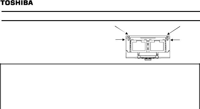
2.Names and functions
The drawing below shows names and functions of main parts.
2.1. Outline
Connector to the inverter
|
LED indicator (See 2.4) |
MS |
NS |
LNK |
LNK |
MAC address Label |
|
|
(Back side) |
Shielded female RJ45 |
Shielded female RJ45 |
|
EtherNet/IP Connector |
EtherNet/IP Connector |
Release tab |
(Port L |
(Port R |
- 4 -
E6581741
2.2. RJ45 connector pin layout
The EtherNet/IP™ - Modbus® TCP option is equipped with two shielded RJ45 connectors.
When you use VF-MB1, the shielding is connected to the drive ground. When you use VF-S15, the shielding is connected to the grounding terminal of option adapter.
Use an STP (shielded twisted pair) Ethernet cable.
The transmission speed is detected automatically by the unit (10 Mbps or 100 Mbps). The card can operate in half duplex or full duplex mode, whether connected to a hub or a switch and regardless of the transmission speed (10 Mbps or 100 Mbps).
|
|
|
|
|
|
|
|
|
|
|
|
|
Pin |
Signal |
|
Port L and Port R |
1 |
TD+ |
|||||||||||||
2 |
TD- |
||||||||||||||
|
|
|
|
|
|
|
|
|
|
|
|
|
|||
|
|
|
|
|
|
|
|
|
|
|
|
|
|||
|
|
|
|
|
|
|
|
|
|
|
|
|
3 |
RD+ |
|
|
|
|
|
|
|
|
|
|
|
|
|
|
|||
|
|
|
|
|
|
|
|
|
|
|
|
|
4 |
- |
|
|
|
|
|
|
|
|
|
|
|
|
|
|
5 |
- |
|
|
|
|
|
|
|
|
|
|
|
|
|
|
|||
|
|
|
|
|
|
|
|
|
|
|
|
|
6 |
RD- |
|
8………………1 |
7 |
- |
|||||||||||||
8 |
- |
||||||||||||||
|
|
|
|
|
|
|
|
|
|
|
|
|
|||
*Fix a cable so that a communication connector may be not taken the weight of wire.
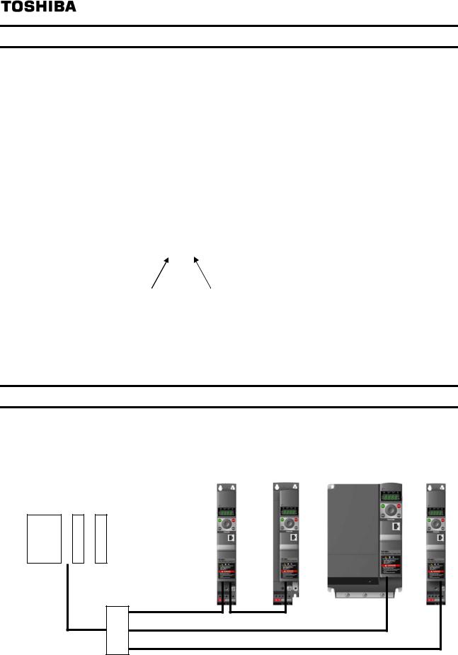
2.3.Example of connection to an EtherNet/IP™ and Modbus® TCP
Example of daisy chain topology and star topology
Daisy chain topology |
Star topology |
PLC
Ethernet switch
- 5 -
E6581741
2.4. LED indicator
The LED shows the present |
MS |
|
|
status of the network and module. |
|
|
LNK |
The behavior of LNK LED
NS
LNK
Link Activity
Protocol |
|
Color and behavior |
Meaning |
EtherNet/IP |
|
OFF |
No link |
& |
|
Flashing Green/Red |
Power up testing |
Modbus TCP |
|
Green ON |
Link at 100Mbps |
|
|
Yellow ON |
Link at 10Mbps |
|
|
Green Blink |
Activity at 100Mbps |
|
|
Yellow Blink |
Activity at 10Mbps |
The behavior of MS LED |
|
||
Module Status |
|
|
|
Protocol |
|
Color and behavior |
Meaning |
|
|
OFF |
No power is supplied to the device |
|
|
Flashing Green/Red |
Power up testing |
EtherNet/IP |
|
Green ON |
The option is operating correctly |
|
Green flashing |
The option has not been configured |
|
|
|
||
|
|
Red flashing |
The option has detected a recoverable minor fault |
|
|
Red on |
The option has detected a non-recoverable major fault |
|
|
OFF |
The option does not have an IP address or powered off |
|
|
Flashing Green/Red |
Power up testing |
Modbus TCP |
|
Green ON |
The option is ready |
|
Green flashing |
The option is not ready (waiting for cable connection or etc.) |
|
|
|
||
|
|
Red flashing |
The option has detected a communication error (err8) |
|
|
Red ON |
The option has detected a option module error (e-23) |
The behavior of NS LED |
|
||
Network Status |
|
|
|
Protocol |
|
Color and behavior |
Meaning |
|
|
OFF |
The option does not have IP address or powered off |
|
|
Flashing Green/Red |
Power up testing |
|
|
Green ON |
The option has at least one established connection |
EtherNet/IP |
|
Green flashing |
The option does not have at least one established connection |
|
Red flashing |
One or more of the connections in which this device is the target |
|
|
|
||
|
|
|
has time out. This shall be left only if all time out connections are |
|
|
|
re-established or if the device is reset |
|
|
Red on |
Error: duplicate IP address |
|
|
OFF |
The option does not have an IP address or powered off |
|
|
Flashing Green/Red |
Power up testing |
|
|
Green ON |
At least one port is connected and an IP address has been |
Modbus TCP |
|
|
obtained |
|
|
Green flashing 3 times |
All ports are unplugged, but the card has an IP address |
|
|
Green flashing 4 times |
Error: duplicate IP address |
|
|
Green flashing 5 times |
The card is performing a BOOTP or DHCP sequence |
- 6 -

E6581741
3.Parameters
3.1. Communication parameters
Set up the inverter parameters as follows. It is necessary to reset the inverter to update the parameter. This option doesn't operate if these parameters are not correctly set.
Title |
Communi |
Function |
Description |
Factory |
|
cation No. |
setting |
||||
|
|
|
|||
|
|
|
0: Terminal board |
|
|
|
|
|
1: Panel keypad (including remote keypad) |
1 |
|
cmod |
0003 |
Command mode selection |
2: RS485 communication |
||
|
|
|
3: CANopen communication |
|
|
|
|
|
4: Communcation option |
|
|
|
|
|
0: Setting dial 1 (save even if power is off) |
|
|
|
|
|
1: Terminal board VIA |
|
|
|
|
|
2: Terminal board VIB |
|
|
|
|
|
3: Setting dial 2 (press in center to save) |
|
|
|
|
|
4: RS485 communication |
|
|
|
|
Frequency setting mode |
5: UP/DOWN from external logic input |
0 |
|
fmod |
0004 |
6: CANopen communication |
|||
selection 1 |
|||||
|
|
7: Communication option |
|
||
|
|
|
|
||
|
|
|
8: Terminal board VIC |
|
|
|
|
|
9, 10: - |
|
|
|
|
|
11: Pulse train input |
|
|
|
|
|
12, 13: - (*1) |
|
|
|
|
|
14: sr0 (*1) |
|
|
|
|
|
1: 2 poles |
|
|
|
|
|
2: 4 poles |
|
|
|
|
|
3: 6 poles |
|
|
f856 |
0856 |
Number of motor pole pair for |
4: 8 poles |
2 |
|
communication |
5: 10 poles |
||||
|
|
|
|||
|
|
|
6: 12 poles |
|
|
|
|
|
7: 14 poles |
|
|
|
|
|
8: 16 poles |
|
|
f899 |
0899 |
Communication function reset |
0: - |
0 |
|
1: Reset (after execution: 0) |
|||||
|
|
|
|
||
(*1): There selections are effective in only VF-S15. |
|
|
|||
|
|
|
|
|
|
Title |
Communi |
Function |
Description |
Factory |
|
cation No. |
setting |
||||
|
|
|
|||
|
|
|
0: - |
1 |
|
|
|
|
1: fa06 (Communication command 1) |
|
|
|
|
|
2: fa23 (Communication command 2) |
|
|
|
|
|
3: fa07 (Frequency command, 0.01Hz) |
|
|
|
|
|
5: fa50 (Terminal output data) |
|
|
c001 |
C001 |
Scanner input 1 address (*3) |
6: fa51 (FM analog output) |
|
|
8: f601 (Stall prevention level, %) |
|
||||
|
|
|
|
||
|
|
|
13: acc (Acceleration time 1, 0.1s) (*2) |
|
|
|
|
|
14: dec (Deceleration time 1, 0.1s) (*2) |
|
|
|
|
|
15: ul (Upper limit, 0.01Hz) |
|
|
|
|
|
16: vb (Torque boost value 1, 0.1%) |
|
|
|
|
|
17: vlv (Base frequency voltage 1, 0.1V) |
|
|
c002 |
C002 |
Scanner input 2 address (*3) |
0-17 (Same as c001) |
3 |
|
c003 |
C003 |
Scanner input 3 address (*3) |
0-17 (Same as c001) |
0 |
|
c004 |
C004 |
Scanner input 4 address (*3) |
0-17 (Same as c001) |
0 |
|
c005 |
C005 |
Scanner input 5 address (*3) |
0-17 (Same as c001) |
0 |
|
c006 |
C006 |
Scanner input 6 address (*3) |
0-17 (Same as c001) |
0 |
|
(*2): The unit depends on the f519 setting.
(*3): This parameter is effective by reset. Please reset (power supply reset or f899=1) after changing a set point.
- 7 -

|
|
|
|
|
|
E6581741 |
||
|
|
|
|
|
|
|
|
|
Title |
Communi |
Function |
|
|
Description |
|
Factory |
|
cation No. |
|
|
|
setting |
||||
|
|
|
|
|
|
|||
|
|
|
0: |
- |
(Status information 1) |
|
1 |
|
|
|
|
1: fd01 |
|
|
|||
|
|
|
2: fd00 |
(Output frequency, 0.01Hz) |
|
|
||
|
|
|
3: fd03 |
(Output current, 0.01%) |
|
|
||
|
|
|
4: fd05 |
(Output voltage, 0.01%) |
|
|
||
|
|
|
5: fc91 |
(Alarm information) |
|
|
||
|
|
|
6: fd22 |
(PID feedback value, 0.01Hz) |
|
|||
|
|
|
7: fd06 |
(Input terminal board status) |
|
|||
|
|
|
8: fd07 |
(Output terminal status) |
|
|
||
|
|
|
9: fe36 |
(VIB input, 0.01%) |
|
|
||
|
|
|
10: fe35 |
(VIA input, 0.01%) |
|
|
||
|
|
|
11: fe37 |
(VIC input, 0.01%) |
|
|
||
|
|
|
12: fd04 |
(Input voltage (DC detection), 0.01%) |
|
|||
|
|
|
13: fd16 |
(Estimated speed 0.01Hz) |
|
|
||
|
|
|
14: fd18 (Torque, 0.01%) |
|
|
|||
|
|
|
15: |
- |
|
|
|
|
|
|
|
16: |
- |
|
|
|
|
c021 |
C021 |
Scanner output 1 address (*3) |
17: |
- |
|
|
|
|
18: |
- |
|
|
|
||||
|
|
|
|
|
|
|||
|
|
|
19: f880 |
(Free notes) |
|
|
||
|
|
|
20: fd29 |
(Input power, 0.01kW) |
|
|
||
|
|
|
21: fd30 |
(Output power, 0.01kW) |
|
|
||
|
|
|
22: fe14 |
(Cumulative operation time, hour) |
|
|||
|
|
|
23: fe40 (FM terminal output monitor, 0.01%) |
|
||||
|
|
|
24: |
- |
|
|
|
|
|
|
|
25: fd20 (Torque current, 0.01%) |
|
|
|||
|
|
|
26: fd23 (Motor overload factor, 0.01%) |
|
||||
|
|
|
27: fd24 (Drive overload factor, 0.01%) |
|
||||
|
|
|
28: fd25 (PBR overload factor, %) |
|
|
|||
|
|
|
29: fd26 (Motor load factor, %) |
|
|
|||
|
|
|
30: fd27 (Drive load factor, %) |
|
|
|||
|
|
|
31: fe56 (Pulse train input, pps) |
|
|
|||
|
|
|
32: fe70 (Drive rated current, 0.1A) |
|
|
|||
|
|
|
33: fe76 (Input Watt-hour, 0.1kWh |
10f749) |
|
|||
|
|
|
34: fe77 (Output Watt-hour, 0.1kWh |
10f749) |
|
|||
|
|
|
35: fd83 (IGBT temperature, degree C) |
|
||||
c022 |
C022 |
Scanner output 2 address (*3) |
0-35 (Same as c021) |
|
2 |
|||
c023 |
C023 |
Scanner output 3 address (*3) |
0-35 (Same as c021) |
|
0 |
|||
c024 |
C024 |
Scanner output 4 address (*3) |
0-35 (Same as c021) |
|
0 |
|||
c025 |
C025 |
Scanner output 5 address (*3) |
0-35 (Same as c021) |
|
0 |
|||
c026 |
C026 |
Scanner output 6 address (*3) |
0-35 (Same as c021) |
|
0 |
|||
|
|
|
16 characters |
|
|
|||
c081- |
C081- |
|
The |
device |
name is required if the |
card uses |
0,0,0,0, |
|
c096 |
C096 |
Device Name 1-16 (*4) |
DHCP to obtain its IP Address. |
|
0,0,0,0 |
|||
Refer to "3.2.1 Device name (c081-c096) for the |
||||||||
|
|
|
|
|||||
|
|
|
details. |
|
|
|
||
c100 |
C100 |
Communication error |
0.0 - 100.0 sec. |
|
0.0 |
|||
detection delay time |
|
|||||||
|
|
|
|
|
|
|
||
|
|
|
0: Stop and controlled by cmod, fmod |
|
||||
|
|
|
1: Operation continue |
|
|
|||
|
C101 |
Inverter operation at the |
2: Deceleration stop |
|
4 |
|||
c101 |
3: Coast stop |
|
||||||
communication loss action |
|
|||||||
|
|
4: Network error stop (err8 trip) |
|
|
||||
|
|
|
|
|
||||
|
|
|
5: Preset speed operation (by c102 setting) |
|
||||
|
|
|
|
|
|
|
||
c102 |
C102 |
Preset speed operation |
0: None |
|
|
0 |
||
selection |
1 to 15: Preset speed |
|
|
|||||
|
|
|
|
|||||
|
|
|
0: Disconnection detection |
|
0 |
|||
|
|
Communication time-out |
1: |
When communication mode enable (Both |
|
|||
c103 |
C103 |
cmod |
and fmod are set CANopen or |
|
||||
condition selection |
|
|||||||
|
|
communication option) only |
|
|
||||
|
|
|
|
|
||||
|
|
|
2: 1 + Driving operation |
|
|
|||
(*3): This parameter is effective by reset. Please reset (power supply reset or f899=1) after changing a set point. (*4): (V[R) does not work for this parameter.
- 8 -

|
|
|
|
E6581741 |
||
|
|
|
|
|
|
|
Title |
Communi |
Function |
|
Description |
Factory |
|
cation No. |
|
setting |
||||
|
|
|
|
|||
|
|
|
This parameter is used to set the protocol of the option |
|
||
c500 |
C500 |
Protocol (*3) |
card. |
0 |
||
0: Modbus TCP (default) |
||||||
|
|
|
|
|||
|
|
|
1: EtherNet/IP |
|
||
|
|
|
This field is used to set the transmission speed and the |
|
||
|
|
|
transmission mode of the card. |
|
||
|
|
Rate Setting (*3) |
0: Autodetect(default) |
0 |
||
c501 |
C501 |
1: 10Mbps Full |
||||
|
|
|
2: 10Mbps Half |
|
||
|
|
|
3: 100Mbps Full |
|
||
|
|
|
4: 100Mbps Half |
|
||
|
|
|
This field displays the baud rate and the transmission |
|
||
c502 |
C502 |
Actual Rate (L port) |
mode currently used by the communication card. |
|
||
(Display only) |
|
|||||
|
|
|
|
|||
|
|
|
0: unconnected |
- |
||
|
|
|
1: 10Mbps Full |
|||
|
|
|
|
|||
c503 |
C503 |
Actual Rate (R port) |
2: 10Mbps Half |
|
||
3: 100Mbps Full |
|
|||||
|
|
|
|
|||
|
|
|
4: 100Mbps Half |
|
||
|
|
|
|
|
||
|
|
|
Use this parameter to select the IP address assignment |
|
||
|
|
|
method. |
|
||
c504 |
C504 |
IP mode (*3) |
0: Manual |
0 |
||
1: BOOTP |
||||||
|
|
|
|
|||
|
|
|
2: DHCP |
|
||
|
|
|
Refer to "3.2.2 Assigning IP addresses" for the details. |
|
||
c505- |
C505- |
|
The IP address of the option module. |
|
||
IP address (*3) |
These fields are effective settings at c504 = 0. |
0.0.0.0 |
||||
c508 |
C508 |
|||||
|
Refer to "3.2.2 Assigning IP addresses" for the details. |
|
||||
|
|
|
|
|||
c509- |
C509- |
|
The subnet mask of the option module. |
|
||
Subnet Mask (*3) |
These fields are effective settings at c504 = 0. |
0.0.0.0 |
||||
c512 |
C512 |
|||||
|
Refer to "3.2.2 Assigning IP addresses" for the details. |
|
||||
|
|
|
|
|||
c513- |
C513- |
|
The gateway IP address of the option module. |
|
||
IP Gate (*3) |
These fields are effective settings at c504 = 0. |
0.0.0.0 |
||||
c516 |
C516 |
|||||
|
Refer to "3.2.2 Assigning IP addresses" for the details. |
|
||||
|
|
|
|
|||
c517- |
C517- |
MAC address (*5) |
The MAC address of the option module. |
---- |
||
c522 |
C522 |
[C517 - C518 - C519 - C520 - C521 - C522] |
||||
|
|
|||||
|
|
|
The waiting time from the occurrence of the |
2 |
||
|
|
|
network error to detection can be adjusted. |
|
||
|
|
|
* When you are using unconnected |
|
||
c523 |
C523 |
Time out |
communication of the EtherNet/IP protocol, time |
|
||
|
|
|
out is not detected. |
|
||
|
|
|
0.0: Disable |
|
||
|
|
|
0.5 - 60 sec. |
|
||
c524- |
C524- |
IP address actual |
The current IP address of the option module. |
- |
||
c527 |
C527 |
Refer to "3.2.2 Assigning IP addresses" for the details. |
||||
|
|
|||||
c528- |
C528- |
IP Mask actual |
The subnet mask actual of the option module. |
- |
||
c531 |
C531 |
Refer to "3.2.2 Assigning IP addresses" for the details. |
||||
|
|
|||||
|
|
|
|
|
||
c532- |
C532- |
IP Gate actual |
The gateway IP address actual of the option module. |
- |
||
c535 |
C535 |
Refer to "3.2.2 Assigning IP addresses" for the details. |
||||
|
|
|||||
(*3): This parameter is effective by reset. Please reset (power supply reset or f899=1) after changing a set point. (*5): .These values are displayed by decimal number format on panel of VFMB1/S15.
- 9 -
|
|
|
|
E6581741 |
|
EtherNet/IP parameters |
|
|
|
||
Title |
Communi |
|
Function |
Description |
Factory |
cation No. |
|
setting |
|||
|
|
|
|
||
|
|
|
|
Monitor of the EtherNet error. |
- |
|
|
|
|
0: No error/clear error |
|
c536 |
C536 |
|
EtherNet Error |
1: Modbus TCP IO Scanning timeout |
|
|
|
|
|
2: Network overload |
|
|
|
|
|
3: Loss of Ethernet carrier |
|
|
|
|
|
Enables web server. |
1 |
c554 |
C554 |
|
Web service (*3) |
0: Disable |
|
|
|
|
|
1: Enable |
|
|
|
|
|
Monitor the inverter status. |
- |
c555 |
C555 |
|
Drive Status |
3: Gate Block |
|
|
4: Run |
|
|||
|
|
|
|
|
|
|
|
|
|
23: Fault |
|
Modbus TCP parameters |
|
|
|
||
Title |
Communi |
|
Function |
Description |
Factory |
cation No. |
|
setting |
|||
|
|
|
|
||
c600- |
C600- |
|
IP Master (*3) |
The IP address for PLC(Master) of the Modbus TCP. |
0.0.0.0 |
c603 |
C603 |
|
|||
|
|
|
|
||
|
|
|
|
Enables IO Scan function. |
0 |
c604 |
C604 |
|
IO Scan active (*3) |
0: Non-active |
|
|
|
|
|
1: Active |
|
(*3): This parameter is effective by reset. Please reset (power supply reset or f899=1) after changing a set point.
|
Warning |
|
Set up “Communication error trip function (c100 to c103 and c523)” to stop the |
Mandatory |
inverter when EtherNet/IP™ - Modbus® TCP communication is deactivated. |
When the parameters are changed, please reset (power supply reset or f899=1) the |
|
action |
inverter for the changes to take effect. |
- 10 -

E6581741
3.2. The details of the parameter setting
3.2.1.Device name (c081-c096)
This option module can set the "Device name" of 16 characters. (Device name (c081-c096) is 1 character within one parameter.)
The device name is required if the option module uses DHCP to obtain its IP Address.
Please set the setting of the device name according to the following rules.
1.The parameter is displayed by the hexadecimal number.
2.One parameter shows an ASCII character.
3.The relation between the device name and the parameter is as follows.
Example for Device Name =’VFMB1-4007PL’
Chars No. |
Parameter |
Character (Ex.) |
ASCII (Ex.) |
1 |
c081 |
‘V’ |
56H |
2 |
c082 |
‘F’ |
46H |
3 |
c083 |
‘M’ |
4DH |
4 |
c084 |
‘B’ |
42H |
5 |
c085 |
‘1’ |
31H |
6 |
c086 |
‘-‘ |
2DH |
7 |
c087 |
‘4’ |
34H |
8 |
c088 |
‘0’ |
30H |
9 |
c089 |
‘0’ |
30H |
10 |
c090 |
‘7’ |
37H |
11 |
c091 |
‘P’ |
50H |
12 |
c092 |
‘L’ |
4CH |
13 |
c093 |
- |
- |
14 |
c094 |
- |
- |
15 |
c095 |
- |
- |
16 |
c096 |
- |
- |
- 11 -

E6581741
3.2.2.Assigning IP addresses (c504, c505-c516)
The drive needs 3 (4-Modbus TCP) IP addresses. *The drive IP address.
*The subnet mask.
*The gateway IP address.
(*The IP Master address.- Modbus TCP protocol only)
These parameters are effective settings at c504 = 0 (IP mode: Manual).
If the address has been given by a BOOTP or a DHCP server, these parameters are invalidity.
•After dynamic addressing by a BOOTP or DHCP server, the new address value is displayed in the parameters. (c524-c535)
They can be provided by:
*BOOTP server (correspondence between the MAC address and the IP addresses). *DHCP server (correspondence between Device Name and the IP addresses).
The address is assigned according to the IP mode parameter.
c504: IP mode |
Comments |
0 |
The option uses the address defined in c505-c516. |
1 |
The option receives its address from a BOOTP server. |
2 |
The option receives its address from a DHCP server. |
|
*Device name contains (c081-c096) a valid name. |
Note: The IP mode parameter may be modified according to the configuration control attribute of the TCP/IP interface object (CIP standard).
- 12 -

E6581741
3.2.3.Network error detection (c100 - c103, c523)
▼Display of trip information
err8 (Optional unit fault 1: 1BH): Network error stop
▼Related parameter
Title |
Function |
Setting range |
Description |
c100 |
Communication error |
0.0-100.0 sec |
|
detection delay time |
|||
|
|
c101 |
Inverter operation at the |
0-5 |
|
communications loss action |
|||
|
|
||
c102 |
Preset speed operation |
1-15 |
|
selection |
|||
|
|
||
|
|
|
|
c103 |
Communication time-out |
0-2 |
|
condition selection |
|||
|
|
||
c523 |
Time out |
0.0: Disable |
|
0.5 - 60 sec. |
|||
|
|
The waiting time from when a network error occurs can be adjusted. If a network error continues past the time set in c100, it is recognized as a communication error and the operation of the inverter follows the setting of c101.
When normal communication returns during the setting time, a communication error is not displayed and operation is continued.
*The case of Modbus® TCP protocol
The time-out detection time provides by c523 parameter.
Disconnection detection time = c523 (Time out) +
c100 (Communication error detection delay time)
*The case of EtherNet/IPTM protocol
-At I/O scanning and connected communication
Time-out time =
RPI 4 2Connection Timeout Multiplier [μs] + c100
(communication error detection delay time) [0.1s] RPI: Request Packet Interval
-At Unconnected communication
Time-out is not operating.
The operation of the inverter when the communication fault occurs can be specified. The operation frequency of the inverter when the
communication fault occurs can be specified. (Only when c101 is set to 5)
Select the communication time-out condition.
The waiting time from the occurrence of the network error to detection can be adjusted.
*When you are using unconnected communication of the EtherNet/IP protocol, time-out is not detected.
- 13 -
E6581741
3.2.4.Command data (c001-c006), Monitor data (c021-c026)
The outline is indicated about the setting item of parameter c001 – c006 and c021 – c026 in Instance 102/152 and 105/155 of use. Please refer to a communication functional description for details.
3.2.4.1. How to use Instance 102/152 and 105/155
Instance 102/152 and 105/155 choose a command or the monitor of the driving state by a menu of c001 - c006 and c021 - c026 and can perform the communication that is cyclic of EtherNet/IP™ and Modbus® TCP (ID = 255).
Example 1: Command transmitting by output Instance 102
If the command value “c400” set to parameter fa06, Choose parameter fa06 (a communication option command) for command data (c001=1 (fa06)).
For example, please set C400 in FA06 when you want to send the command from an EtherNet/IP™ option and the availability of the frequency order and a driving order. (Please refer to ”3.2.4.2”)
VF-MB1/S15 |
|
IPE002Z |
EtherNet/IP Master |
|
|
|
Output Instance 102 |
||
|
|
|
||
Parameter |
Value |
|
Byte |
Value |
c001 |
1 (fa06) |
|
0 |
00 |
c002 |
... |
|
1 |
C4 |
c003 |
... |
|
2 |
... |
... |
... |
|
3 |
... |
"0xC400" is set to parameter fa06 |
|
... |
... |
|
|
|
|
||
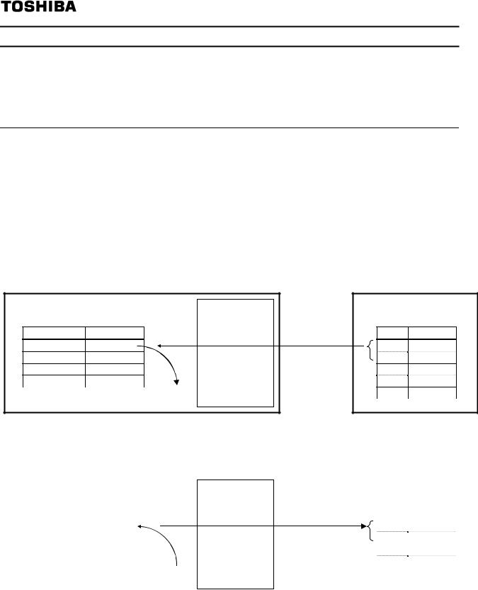
Example 2: State monitoring by the input instance 152.
When you want to monitor the output current, set “3 (fd03)” to parameter c021.
The value of the parameter fd03 specified as 0 and 1 byte of the input instance 152 with the parameter c021 is inputted.
VF-MB1/S15 |
|
|
IPE002Z |
|
EtherNet/IP Master |
|
|||
|
|
|
|
|
|
Input Instance 152 |
|
||
|
|
|
|
|
|
|
|
||
|
|
|
|
|
|
|
|
|
|
|
Parameter |
Value |
|
|
|
|
Byte |
Value |
|
|
c021 |
3 (fd03) |
|
|
|
|
0 |
34 |
|
|
c022 |
... |
|
|
|
|
1 |
12 |
|
|
c023 |
... |
|
|
|
|
2 |
... |
|
|
... |
... |
|
|
|
|
3 |
... |
|
The value of a parameter fd03 (0x1234) |
|
|
|
... |
... |
|
|||
is outputted. |
|
|
|
|
|
|
|
|
|
|
|
|
|
|
|
|
|
|
|
- 14 -

E6581741
fa06 (Communication command1)
bit |
Function |
0 |
1 |
Note |
|
|
Preset speed |
|
|
|
|
0 |
operation frequencies |
|
|
|
|
|
1 |
|
|
|
|
|
Preset speed |
0000: Preset speed operation OFF |
Preset speed operation is |
||
1 |
operation frequencies |
||||
(*1) |
|
disabled or preset speed |
|||
|
2 |
|
|||
|
|
|
operation frequencies (1-15) are |
||
|
Preset speed |
|
|
||
|
0001-1111: Setting of preset speed |
set by specifying bits for preset |
|||
2 |
operation frequencies |
||||
operation frequencies (1-15) |
speed operation frequencies 1-4. |
||||
|
3 |
||||
|
|
|
|
||
|
Preset speed |
|
|
|
|
3 |
operation frequencies |
|
|
|
|
|
4 |
|
|
|
|
|
Motor selection (1 or 2) |
Motor 1 |
Motor 2 |
THR 1: pt = setting value, thr |
|
4 |
THR 2: pt = 0, f170, |
||||
(THR 2 selection) |
(THR 1) |
(THR 2) |
|||
|
f171, f172, f173 |
||||
|
|
|
|
||
5 |
PI D control |
Normal operation |
PI D off |
- |
|
|
Acceleration/decele- |
Acceleration/decel |
Acceleration/dec |
|
|
6 |
ration pattern selection |
eration pattern 1 |
eleration pattern |
AD1: acc, dec |
|
|
(1 or 2) |
(AD1) |
2 |
AD2: f500, f501 |
|
|
(AD2 selection) |
(AD2) |
|
||
|
|
|
|||
7 |
DC braking |
OFF |
Forced DC |
- |
|
braking |
|||||
|
|
|
|
||
8 |
Jog run |
OFF |
Jog run |
- |
|
9 |
Forward/reverse run |
Forward run |
Reverse run |
- |
|
selection |
|||||
|
|
|
|
||
10 |
Run/stop |
Stop |
Run |
- |
|
11 |
Coast stop command |
Standby |
Cost stop |
- |
|
12 |
Emergency stop |
OFF |
Emergency stop |
Always enable, "E" trip |
|
13 |
Fault reset |
OFF |
Reset |
No data is returned from the drive |
|
14 |
Frequency priority |
OFF |
Enabled |
Enabled regardless of the setting |
|
selection |
of fmod |
||||
|
|
|
|||
15 |
Command priority |
OFF |
Enabled |
Enabled regardless of the setting |
|
selection |
of cmod |
||||
|
|
|
|||
(*1): When 14(sr0) is set to fmod, preset speed operation frequency 0 is selected in using VFS15,.
- 15 -

|
|
|
|
E6581741 |
|
3.2.4.3. fa23 (Communication command 2) |
|
||||
|
|
|
|
|
|
bit |
Function |
0 |
1 |
Note |
|
|
|
|
|
|
|
0 |
(Reserved) |
- |
- |
- |
|
1 |
Electric power quantity |
OFF |
Reset |
Electric power quantity (fe76, |
|
reset |
fe77) reset |
||||
|
|
|
|||
2 |
(Reserved) |
- |
- |
- |
|
3 |
(Reserved) |
- |
- |
- |
|
4 |
(Reserved) |
- |
- |
- |
|
5 |
(Reserved) |
- |
- |
- |
|
6 |
(Reserved) |
- |
- |
- |
|
7 |
Maximum deceleration |
Normal |
Enabled |
- |
|
forced stop |
|||||
|
|
|
|
||
8 |
Acceleration/decele- |
00: Acceleration/deceleration 1 |
Select acceleration/deceleration |
||
1-3 by combination of two bits.. |
|||||
ration selection 1 |
|||||
|
01: Acceleration/deceleration 2 |
AD1: acc, dec |
|||
|
Acceleration/decele- |
||||
|
|||||
9 |
10: Acceleration/deceleration 3 |
AD2: f500, f501 |
|||
ration selection 2 |
|
|
AD3: f510, f511 |
||
|
|
|
|||
10 |
(Reserved) |
- |
- |
- |
|
11 |
(Reserved) |
- |
- |
- |
|
12 |
OC stall level switch |
OC stall 1 |
OC stall 2 |
OC stall 1: f601 |
|
OC stall 2: f185 |
|||||
|
|
|
|
||
13 |
(Reserved) |
- |
- |
- |
|
14 |
(Reserved) |
- |
- |
- |
|
15 |
(Reserved) |
- |
- |
- |
|
Note: Set 0 to reserved bit.
- 16 -

E6581741
3.2.4.4. fa07 (frequency reference from internal option)
Frequency reference is set up by 0.01Hz unit and the hexadecimal number.
For example, when "Frequency reference" is set up to 80Hz, since the minimum unit is 0.01Hz, 80 / 0.01 = 8000 = 0x1F40 (Hex.)
3.2.4.5. fa50 (Terminal output data from communication)
The output data on the terminal board can be directly controlled with the computer.
To use this function, select functions from 92 to 95 in advance for the output terminal selection parameters f130, f131, f132. If bit 0 through bit1 of the data (fa50) is set with the computer, the specified data (0 or 1) can be output to the selected output terminal.
Data composition of output data on the terminal board (FA50)
bit |
Output TB function name |
0 |
1 |
|
0 |
Specified data output 1 |
OFF |
ON |
|
(Output terminal No.: 92, 93) |
||||
|
|
|
||
1 |
Specified data output 2 |
OFF |
ON |
|
(Output terminal No.: 94, 95 |
||||
|
|
|
||
2-15 |
(Reserved) |
- |
- |
Note: Set 0 to reserved bit
Example of use: To control only the RY-RC terminal with the computer
To turn on the RY terminal, set the output terminal selection 1A parameter (f130) to 92 (Designated data output 1) and set 0001H to fa50.
FA50: |
BIT15 |
|
|
|
|
|
|
|
|
|
|
|
|
|
|
|
|
|
BIT0 |
|||
|
0 |
|
0 |
|
0 |
0 |
0 |
0 |
0 |
0 |
0 |
0 |
|
0 |
0 |
0 |
0 |
|
0 |
1 |
|
|
|
|
|
|
|
0 |
|
|
0 |
|
|
|
|
0 |
|
|
|
1 |
|
|
|||
3.2.4.6. fa51 (Analog output (FM) data from communication)
Use this function, set the FM terminal meter selection parameter (fmsl) to 18 (communication data output).
This makes it possible to send out the data specified as FM analog output data (fa51) though the FM analog output terminal. Data can be adjusted in a range of 0 to 1000 (resolution of 10 bit).
Please refer to "Meter setting and adjustment" Section of the inverter’s instruction manual.
- 17 -

E6581741
3.2.4.7. fd01 (Inverter operating status 1)
bit |
Function |
0 |
1 |
Note |
|
0 |
Failure FL |
No output |
Under in |
- |
|
progress |
|||||
|
|
|
Trip status includes rtry and |
||
|
|
|
|
||
1 |
Failure |
Not tripped |
Tripped |
the trip retention status are also |
|
|
|
|
|
regarded as tripped statuses. |
|
2 |
Alarm |
No alarm |
Alarm issued |
- |
|
3 |
Under voltage (moff) |
Normal |
Under voltage |
- |
|
|
|
|
|
THR1: pt = setting value, vl, |
|
4 |
Motor selection (1 or 2) |
Motor 1 (THR1) |
Motor 2 (THR2) |
vlv, vb, thr |
|
(THR 2 selection) |
THR2: pt = 0, f170, f171, |
||||
|
|
PID control |
PID control |
f172, f173 |
|
5 |
PID control off |
- |
|||
permitted |
prohibits |
||||
|
|
|
|||
|
Acceleration/deceleratio |
Acceleration/dec |
Acceleration/dec |
AD1: acc, dec |
|
6 |
n pattern selection (1 or |
eleration pattern |
eleration pattern |
AD2: f500, f501 |
|
|
2) |
1 (AD1) |
2 (AD2) |
|
|
7 |
DC braking |
OFF |
Forced DC |
- |
|
braking |
|||||
|
|
|
|
||
8 |
Jog run |
OFF |
Jog run |
- |
|
9 |
Forward / reverse run |
Forward run |
Reverse run |
- |
|
10 |
Run/stop |
Stop |
Run |
- |
|
11 |
Coast stop (ST = OFF) |
ST=ON |
ST=OFF |
- |
|
12 |
Emergency stop |
No emergency |
Emergency |
- |
|
stop status |
stop status |
||||
|
|
Standby: Initialization |
|||
|
|
|
|
||
|
|
|
|
completed, not failure stop |
|
13 |
Standby ST=ON |
Start-up process |
Standby |
status, not alarm stop status |
|
|
|
|
|
(moff, ll forced stop), |
|
|
|
|
|
ST=ON, and RUN=ON |
|
|
|
|
|
Standby: Initialization completed, |
|
14 |
Standby |
Start-up process |
Standby |
not failure stop status and not |
|
alarm stop status (moff, ll |
|||||
|
|
|
|
||
|
|
|
|
forced stop) |
|
15 |
(Reserved) |
Undefined |
- |
||
Note: Don’t use the reserved bit for the judgment.
3.2.4.8. fd00 (Output frequency)
The current output frequency is read into 0.01Hz of units and by the hexadecimal number. For example, when the output frequency is 80Hz, 0x1F40 (hexadecimal number) are read.
Since the minimum unit is 0.01%,
0x1F40 (Hex.) = 8000(Dec.) * 0.01 = 80 (Hz) |
|
Also about the following parameters, these are the same as this. |
|
- fd22 (Feedback value of PID)............................................... |
Unit: 0.01Hz |
- fd16 (Estimated speed) ........................................................ |
Unit: 0.01Hz |
- fd29 (Input power) ................................................................ |
Unit: 0.01kW |
- fd30 (Output power) ............................................................. |
Unit: 0.01kW |
- 18 -

E6581741
3.2.4.9. fd03 (Output current)
The output current is read into 0.01% of units and by the hexadecimal number.
For example, when the output current of the rated current 4.8A drive is 50% (2.4A), 0x1388 (hexadecimal number) is read out.
Since the minimum unit is 0.01%, |
|
|
0x1388 (Hex.) = 5000 (Dec.) * 0.01 = 50 (%) |
|
|
Also about the following parameters, these are the same as this. |
|
|
- fd05 (Output voltage (real time))............................................. |
Unit: 0.01% |
(V) |
- fd04 (Voltage at DC bus (real time)) ....................................... |
Unit: 0.01% |
(V) |
- fd18 (Torque) .......................................................................... |
Unit: 0.01% |
(Nm)* |
*When the motor information connected to the drive set to the parameter (f405 - f415), torque monitor value "100%" is same as the rated torque of a motor in general.
3.2.4.10. fe35, fe36, fe37 (Monitoring of the analog input VIA, VIB, VIC)
VIA terminal board monitor: "Communication Number fe35"
VIB terminal board monitor: "Communication Number fe36"
VIC terminal board monitor: "Communication Number fe37"
These monitors can also be used as A/D converters irrespective of the drive's control.
VIA / VIC terminal board monitor is capable of reading the data from external devices in a range of 0.01 to 100.00% (unsigned data: 0x0000 to 0x2710).
VIB terminal board monitor is capable of reading the data from external devices in a range of -100.00 to 100.00% (signed data: 0xD8F0 to 0x2710).
If analog input mode is selected with the frequency setting mode selection parameter, however, keep in mind that any data entered via an analog terminal is regarded as a frequency command.
3.2.4.11. fe14 (Cumulative run time)
The operated cumulative time is read by the hexadecimal number.
For example, when cumulative operation time is 18 hours, 0x0012 (18 hours) is read. 0x0012 = 18 (Dec., hour)
3.2.4.12. fe40 (Analog output (FM))
The output value of FM terminal is read.
The value range is set to 0 to 10000 (0x0000 to 2710H) which is corresponded to 0.00% to 100.00%.
For example, when analog output is 50.00%, 0x1388 is read. 0x1388 = 50.00(Dec., %)
- 19 -
E6581741
3.2.4.13. fc91 (Alarm code)
bit |
Function |
|
|
|
Remarks |
0 |
1 |
(Code displayed on |
|||
|
|
|
|
|
the panel) |
0 |
Over-current alarm |
Normal |
|
Alarming |
c flicking |
1 |
Inverter over load alarm |
Normal |
|
Alarming |
l flicking |
2 |
Motor over load alarm |
Normal |
|
Alarming |
l flicking |
3 |
Over heat alarm |
Normal |
|
Alarming |
h flicking |
4 |
Over voltage alarm |
Normal |
|
Alarming |
p flicking |
5 |
Main circuit undervoltage alarm |
Normal |
|
Alarming |
- |
6 |
main device overheat alarm |
Normal |
|
Alarming |
l flicking |
7 |
Under current alarm |
Normal |
|
Alarming |
- |
8 |
Over-torque alarm |
Normal |
|
Alarming |
- |
9 |
Braking resistor overload alarm |
Normal |
|
Alarming |
- |
10 |
Cumulative operation hours alarm |
Normal |
|
Alarming |
- |
11 |
Option communication alarm |
Normal |
|
Alarming |
- |
12 |
Serial communication alarm |
Normal |
|
Alarming |
- |
13 |
MOFFMS (MSrelay off or MOFF) |
Normal |
|
Alarming |
- |
14 |
Stop after instantaneous power off |
- |
|
Dec., Under |
Refer to f302 |
|
stop |
value |
|||
|
|
|
|
||
15 |
Stop after LL continuance time |
- |
|
Dec., Under |
Refer to f256 |
|
stop |
value |
|||
|
|
|
|
||
3.2.4.14. fd06 (Input TB Status)
bit |
TB Name |
|
|
|
|
|
|
|
Function (Parameter) |
|
|
|
|
|
|
0 |
|
1 |
|||||||||
0 |
F |
|
|
Input terminal function selection 1 (f111) |
|
|
|
|
|
|
|
||||||||||||||||
1 |
R |
|
|
Input terminal function selection 2 (f112) |
|
|
|
|
|
|
|
||||||||||||||||
2 |
RES |
|
|
Input terminal function selection 3 (f113) |
|
|
|
|
|
|
|
||||||||||||||||
3 |
S1 |
|
|
Input terminal function selection 4 (f114) |
|
|
|
OFF |
|
ON |
|||||||||||||||||
4 |
S2 |
|
|
Input terminal function selection 5 (f115) |
|
|
|
|
|||||||||||||||||||
|
|
|
|
|
|
|
|
|
|||||||||||||||||||
5 |
S3 |
|
|
Input terminal function selection 6 (f116) |
|
|
|
|
|
|
|
||||||||||||||||
6 |
VIB*1 |
|
|
Input terminal function selection 7 (f117) |
|
|
|
|
|
|
|
||||||||||||||||
7 |
VIA*1 |
|
|
Input terminal function selection 8 (f118) |
|
|
|
|
|
|
|
||||||||||||||||
5 to 15 |
(Reserved) |
|
|
- |
|
|
|
|
|
|
|
|
|
|
|
|
|
|
|
|
|
|
|
|
Undefined |
||
Note: Don't use the reserved bit for the judgment. |
|
|
|
|
|
|
|
|
|
|
|
|
|
|
|||||||||||||
*1: VIA/ VIB are input terminal function when f109 is logic input. |
|
|
|
|
|
|
|
|
|||||||||||||||||||
*The input terminal function is selected by each parameter. |
|
|
|
|
|
|
|
|
|
|
|||||||||||||||||
Example: Data set for FE06 when the F and RES terminals are ON = 0005H |
|
|
|||||||||||||||||||||||||
|
BIT15 |
|
|
|
|
|
|
|
|
|
|
|
|
|
|
|
|
|
BIT0 |
|
|
||||||
|
FE06: |
|
0 |
|
0 |
|
0 |
0 |
0 |
0 |
0 |
0 |
0 |
0 |
|
0 |
0 |
0 |
1 |
|
0 |
1 |
|
|
|
||
|
|
|
|
|
|
|
0 |
|
|
0 |
|
|
|
|
0 |
|
|
|
5 |
|
|
|
|
|
|||
- 20 -

E6581741
3.2.4.15. fd07 (Output TB Status)
bit |
TB Name |
|
|
|
|
|
|
|
Function (Parameter) |
|
|
|
|
|
0 |
|
1 |
|||||||||
0 |
RY-RC |
|
|
Output terminal function selection 1A (f130) |
|
OFF |
|
ON |
||||||||||||||||||
1 |
OUT |
|
|
Output TB Function select |
2A (f131) |
|
|
|
OFF |
|
ON |
|||||||||||||||
2 |
FL |
|
|
Output TB Function select |
3 (f132) |
|
|
|
OFF |
|
ON |
|||||||||||||||
3 - 15 |
(Reserved) |
|
|
|
|
|
|
|
|
|
|
- |
|
|
|
|
|
|
|
|
|
|
|
Undefined |
||
Note: Don't use the reserved bit for the judgment. |
|
|
|
|
|
|
|
|
|
|
|
|
|
|||||||||||||
Example: Data set for FE07 when the RY and FL terminals are ON = 0005H |
|
|
||||||||||||||||||||||||
|
BIT15 |
|
|
|
|
|
|
|
|
|
|
|
|
|
|
|
|
BIT0 |
|
|
||||||
|
FE07: |
|
0 |
|
0 |
|
0 |
0 |
0 |
0 |
0 |
0 |
0 |
0 |
|
0 |
0 |
0 |
1 |
|
0 |
1 |
|
|
|
|
|
|
|
|
|
|
|
0 |
|
|
0 |
|
|
|
|
0 |
|
|
5 |
|
|
|
|
|
|||
- 21 -

E6581741
4.Objects
This section contains the object specifications for all EtherNet/IP objects currently supported by the “IPE002Z”. Table 1 outlines those objects covered:
Class Code |
Object Class |
Page |
||
Hex. |
Dec. |
|||
|
|
|||
0x01 |
1 |
Identity Object |
23 |
|
0x02 |
2 |
Message Router Object |
25 |
|
0x04 |
4 |
Assembly Object |
26 |
|
0x06 |
6 |
Connection Manager Object |
27 |
|
0x28 |
40 |
Motor Data Object |
28 |
|
0x29 |
41 |
Control Supervisor Object |
29 |
|
0x2A |
42 |
AC/DC Drive Object |
32 |
|
0x64 |
100 |
Parameter Object |
33 |
|
0x65 |
101 |
Parameter Object |
35 |
|
0xF4 |
244 |
Port Object |
36 |
|
0xF5 |
245 |
TCP/IP Interface Object |
37 |
|
0xF6 |
246 |
Ethernet Link Object |
39 |
|
Table 1: Supported Objects
For definitions of all data types referred to in these object specifications, refer to the ODVA EtherNet/IP™ Specifications. In general, however, the following are some of the most prevalent types:
BOOL .......................... |
Boolean |
0(False) or 1(TRUE) |
SINT............................ |
Signed Short Integer |
-128 to 127 |
INT .............................. |
Integer |
-32768 to 32767 |
DINT............................ |
Double Integer |
-231 to 231-1 |
USINT ......................... |
Unsigned Short Integer |
0 to 255 |
UINT............................ |
Unsigned Integer |
0 to 65535 |
UDINT ......................... |
Unsigned Double Integer |
0 to 232-1 |
STRING ...................... |
character string (1 byte per character) |
|
SHORT_STRING........ |
character string (1 byte per character, 1 byte length indicator) |
|
BYTE........................... |
Bit string - 8-bits |
|
WORD......................... |
Bit string - 16-bits |
|
DWORD ...................... |
Bit string - 32-bits |
|
EPATH ........................ |
CIP path segments |
|
- 22 -

E6581741
4.1. Identity Object (0x01)
Class code 0x01.
This object provides identification of and general information about the device.
Class Attributes
Instance |
|
Attribute ID |
Access |
Name |
Data type |
Details |
|
Value |
|
1 |
Get |
Revision |
UINT |
Revision of this object |
1 |
||
|
2 |
Get |
Max Instances |
UINT |
Maximum instance number of an |
1 |
||
|
|
|
|
|
|
object currently created in this class |
|
|
|
|
|
|
|
|
level of the device. |
|
|
|
3 |
Get |
Number of Instances |
UINT |
Number of object instances currently |
1 |
||
|
|
|
|
|
|
created at this class level of the |
|
|
|
|
|
|
|
|
device. |
|
|
|
4 |
Get |
Optional attribute list |
STRUCT |
List of optional instance attributes |
0 |
||
|
|
|
|
|
of |
utilized in an object class |
|
|
0 |
|
|
|
|
|
implementation. |
|
|
|
|
|
Number of attributes |
UNIT |
Number of attribute in the optional |
- |
||
|
|
|
|
|||||
|
|
|
|
|
|
attribute list. |
|
|
|
|
|
|
Optional attributes |
ARRAY of |
List of optional attribute numbers. |
- |
|
|
|
|
|
|
UNIT |
|
|
|
|
6 |
Get |
Max ID of class |
UINT |
The attribute ID number of the last |
7 |
||
|
|
|
|
attributes |
|
class attribute of the class definition |
|
|
|
|
|
|
|
|
implemented in the device. |
|
|
|
7 |
Get |
Max ID of instance |
UINT |
The attribute ID number of the last |
7 |
||
|
|
|
|
attribute |
|
instance attribute of the class |
|
|
|
|
|
|
|
|
definition implemented in the device. |
|
|
Class Service
|
Service Code |
Service Name |
|
Read all attributes |
Description of Service |
|
||||||
|
0x01 |
Get_Attribute_All |
|
|
|
|
|
|||||
|
0x0E |
Get_Attribute_Single |
Read one attribute |
|
|
|
||||||
|
Instance Attributes |
|
|
|
|
|
|
|
|
|
||
|
Instance |
Attribute ID |
Access |
|
Name |
|
Data type |
Details |
Value |
|||
|
|
|
1 |
Get |
|
Vendor ID |
|
UINT |
Identification of vendor by number |
377 |
||
|
|
|
2 |
Get |
|
Device type |
|
UINT |
AC/DC Drive profile |
2 |
||
|
|
|
3 |
Get |
|
Product code |
|
UINT |
Identification No. of a drive |
|
||
|
|
|
|
|
|
|
|
|
|
|
(case of VF-MB1) |
32000 |
|
|
|
|
|
|
|
|
|
|
|
(case of VF-S15) |
32001 |
|
|
|
4 |
Get |
|
Revision |
|
STRUCT |
Revision of the item the Identity |
|
||
|
|
|
|
|
|
|
|
|
|
of |
Object represents |
|
|
1 |
|
|
|
|
Major revision |
|
USINT |
Major revision of drive |
1 (*1) |
||
|
|
|
|
|
Minor revision |
|
USINT |
Minor revision of drive |
8 (*1) |
|||
|
|
|
|
|
|
|
||||||
|
|
|
5 |
Get |
|
Status |
|
WORD |
See “Attribute 5 State Description” |
* |
||
|
|
|
6 |
Get |
|
Serial number |
|
UDINT |
4 last bytes of MAC Address |
- |
||
|
|
|
7 |
Get |
|
Product name |
|
SHOT_ |
Human readable identification |
|
||
|
|
|
|
|
|
|
|
|
|
STRING |
(case of VF-MB1 drive) |
6, |
|
|
|
|
|
|
|
|
|
|
|
|
VF-MB1 |
|
|
|
|
|
|
|
|
|
|
|
(case of VF-S15 drive) |
6, |
|
|
|
|
|
|
|
|
|
|
|
|
VF-S15 |
*1: These values depend on firmware version and revision.
Instance Services
Service Code |
Service Name |
Description of Service |
0x01 |
Get_Attribute_All |
Read all attributes |
0x05 |
Reset |
Invokes the Reset for the device |
0x0E |
Get_Attribute_Single |
Read one attribute |
- 23 -

E6581741
Attribute 5 State Descriptions
Adapted from document [CIP] “THE CIP NETWORKS LIBRARY”
Bit |
Called |
|
Definition |
|
||
|
|
|
TRUE indicates the device (or an object within the device) has an owner. |
|||
|
|
|
Within the Master/Slave paradigm the setting of this bit means that the |
|||
0 |
Owned |
|
Predefined Master/Slave Connection Set has been allocated to a master. |
|||
|
|
|
Outside the Master/Slave paradigm the meaning of this bit is TBD. |
|||
|
|
|
Æ unsupporteed |
|||
1 |
|
- |
(System reserved) |
|||
|
|
|
TRUE indicates the application of the device has been configured to do |
|||
2 |
Configured. |
something different than the “out–of–box” default. This shall not include |
||||
|
|
|
configuration of the communications. |
|||
3 |
|
- |
(System reserved) |
|||
|
|
|
0000 |
|
Self-Testing or unknown |
|
|
|
|
0001 |
|
Firmware update in progress |
|
|
|
|
0010 |
|
At least one faulted I/O connection |
|
|
Extended Device |
0011 |
|
No I/O connections established |
||
4-7 |
0100 |
|
Non-Volatile configuration bad |
|||
Status |
|
0101 |
|
Major Fault – either bit 10 or bit 11 is true (1) |
||
|
|
|
||||
|
|
|
0110 |
|
At least one I/O connection in run mode |
|
|
|
|
0111 |
|
At least one I/O connection established, all in idle mode |
|
|
|
|
1000- |
|
Unused |
|
|
|
|
1111 |
|
|
|
|
Minor |
Recoverable |
TRUE indicates the device detected a problem with itself, which is thought to |
|||
8 |
be recoverable. The problem does not cause the device to go into one of the |
|||||
|
Fault |
|
faulted states. |
|||
|
|
|
||||
|
Minor |
|
TRUE indicates the device detected a problem with itself, which is thought to |
|||
9 |
Unrecoverable |
be unrecoverable. The problem does not cause the device to go into one of |
||||
|
Fault. |
|
the faulted states. |
|||
10 |
Major |
Recoverable |
TRUE indicates the device detected a problem with itself, which caused the |
|||
Fault. |
|
device to go into the “Major Recoverable Fault” state. |
||||
|
|
|||||
11 |
Major |
|
TRUE indicates the device detected a problem with itself, which caused the |
|||
Unrecoverable Fault |
device to go into the “Major Unrecoverable Fault” state. |
|||||
|
||||||
12-15 |
|
- |
(System reserved) |
|||
|
Note: Don’t use the |
“System reserved” bit and Bit0 for the judgement. |
||||
- 24 -

E6581741
4.2. Message Router Object (0x02)
Class code 0x02.
The Message Router Object provides a messaging connection point through which a Client may address a service to any object class or instance residing in the physical device.
Class Attributes
Instance |
|
Attribute ID |
Access |
Name |
Data type |
Details |
|
Value |
|
1 |
Get |
Revision |
UINT |
Revision of this object |
1 |
||
|
2 |
Get |
Max Instances |
UINT |
Maximum instance number of an |
1 |
||
|
|
|
|
|
|
object currently created in this class |
|
|
|
|
|
|
|
|
level of the device. |
|
|
|
3 |
Get |
Number of Instances |
UINT |
Number of object instances currently |
1 |
||
|
|
|
|
|
|
created at this class level of the |
|
|
|
|
|
|
|
|
device. |
|
|
|
4 |
Get |
Optional attribute list |
STRUCT |
List of optional instance attributes |
2 |
||
|
|
|
|
|
of |
utilized in an object class |
|
|
0 |
|
|
|
|
|
implementation. |
|
|
|
|
|
Number of attributes |
UNIT |
Number of attribute in the optional |
2 |
||
|
|
|
|
|||||
|
|
|
|
|
|
attribute list. |
|
|
|
|
|
|
Optional attributes |
ARRAY of |
List of optional attribute numbers. |
3 |
|
|
|
|
|
|
UNIT |
|
|
|
|
6 |
Get |
Max ID of class |
UINT |
The attribute ID number of the last |
7 |
||
|
|
|
|
attributes |
|
class attribute of the class definition |
|
|
|
|
|
|
|
|
implemented in the device. |
|
|
|
7 |
Get |
Max ID of instance |
UINT |
The attribute ID number of the last |
3 |
||
|
|
|
|
attribute |
|
instance attribute of the class |
|
|
|
|
|
|
|
|
definition implemented in the device. |
|
|
Class Service
|
Service Code |
Service Name |
Read one attribute |
Description of Service |
|
||||||
|
0x0E |
Get_Attribute_Single |
|
|
|
||||||
|
Instance Attribute |
|
|
|
|
|
|
|
|
||
|
Instance |
Attribute ID |
Access |
Name |
|
Data type |
Details |
Value |
|||
|
|
|
2 |
Get |
Number Available |
|
UNIT |
Maximum number of connections |
16 |
||
|
1 |
|
|
|
|
|
|
|
|
supported |
|
|
|
3 |
Get |
Number active |
|
UNIT |
Number of connections currently |
0 |
|||
|
|
|
|
||||||||
|
|
|
|
|
|
|
|
|
|
used by system components |
|
|
Instance Services |
|
|
|
|
|
Description of Service |
|
|||
|
Service Code |
Service Name |
|
|
|
|
|||||
|
0x0E |
Get_Attribute_Single |
|
Read one attribute |
|
|
|||||
- 25 -

E6581741
4.3. Assembly Object (0x04)
Class code 0x04.
The Assembly Object binds attributes of multiple objects, which allows data to or from each object to be sent or received over a single connection. Assembly objects can be used to bind input data or output data. The terms ”input” and ”output” are defined from the network’s point of view. An input will produce data on the network and an output will consume data from the network
Class Attributes
Instance |
Attribute ID |
Access |
Name |
Data type |
Details |
Value |
|
1 |
Get |
Revision |
UINT |
Revision of this object |
2 |
|
2 |
Get |
Max Instances |
UINT |
Maximum instance number of an |
199 |
|
|
|
|
|
object currently created in this class |
|
|
|
|
|
|
level of the device. |
|
|
3 |
Get |
Number of Instances |
UINT |
Number of object instances currently |
13 |
0 |
|
|
|
|
created at this class level of the |
|
|
|
|
|
device. |
|
|
|
6 |
Get |
Max ID of class |
UINT |
The attribute ID number of the last |
7 |
|
|
|
attributes |
|
class attribute of the class definition |
|
|
|
|
|
|
implemented in the device. |
|
|
7 |
Get |
Max ID of instance |
UINT |
The attribute ID number of the last |
4 |
|
|
|
attribute |
|
instance attribute of the class |
|
|
|
|
|
|
definition implemented in the device. |
|
Class Service
|
Service Code |
|
Service Name |
|
|
Description of Service |
||
|
0x0E |
|
Get_Attribute_Single |
Read one attribute |
|
|||
|
Instance Attribute |
|
|
|
|
|
||
|
Instance |
Attribute ID |
Access |
Name |
Details |
|||
|
See below |
3 |
|
Get/Set* |
Data |
Settable Only on Output Assembly. |
||
|
|
|
|
|
|
|
|
See below |
|
See below |
4 |
|
Get |
Size |
Number of bytes in Attribute 3. |
||
Output Assembly:
|
Instance |
Type |
|
|
Size |
|
Page |
|
|
20 |
CIP basic speed control output |
2 words (4 bytes) |
45 |
||||
|
21 |
CIP extended speed control output |
2 words (4 bytes) |
46 |
||||
|
100 |
Native drive output |
|
2 to 8 words (4 to 16 bytes) |
47 |
|||
|
101 |
Native drive output |
|
4 words (8 bytes) |
49 |
|||
|
102 |
Native drive output |
|
6 words (12 bytes) |
51 |
|||
|
105 |
TOSHIBA specific output |
|
9 words (18 bytes) |
52 |
|||
|
Input Assembly: |
|
|
|
|
|
||
|
Instance |
Type |
|
|
Size |
|
Page |
|
|
70 |
CIP basic speed control input |
2 words (4 bytes) |
|
45 |
|||
|
71 |
CIP extended speed control input |
2 words (4 bytes) |
|
46 |
|||
|
150 |
Native drive input |
|
2 to 8 words (4 to 16 bytes) |
|
47 |
||
|
151 |
Native drive input |
|
4 words (8 bytes) |
|
49 |
||
|
152 |
Native drive input |
|
6 words (12 bytes) |
|
51 |
||
|
155 |
TOSHIBA specific output |
|
9 words (18 bytes) |
|
52 |
||
|
Instance Services |
|
|
Description of Service |
|
|
||
|
Service Code |
|
Service Name |
Read one attribute |
|
|
||
|
0x0E |
|
Get_Attribute_Single |
|
|
|
||
|
0x10 |
|
Set_Attribute_Single |
Write one attribute |
|
|
|
|
- 26 -
Loading...