


 Loading...
SERVICE HANDBOOK
FACSIMILE
GD-1210/1250/1270/1160/1260
File No. SHE060003G0
R060121A4600-TTEC
Ver07_2011-12

Trademarks
•The official name of Windows XP is Microsoft Windows XP Operating System.
•The official name of Windows 7 is Microsoft Windows 7 Operating System.
•Microsoft, Windows, Windows NT, Windows Vista and the brand names and product names of other Microsoft products are trademarks or registered trademarks of Microsoft Corporation in the U.S. and/or other countries.
•Apple, AppleTalk, Macintosh, and Mac are trademarks of Apple Computer, Inc. in the U.S. and other countries.
•PostScript is a trademark of Adobe Systems Incorporated.
•NOVELL, NetWare, and NDS are trademarks or registered trademarks of Novell, Inc.
•Molykote is a registered trademark of Dow Corning Corporation.
•Other company names and product names in this manual are the trademarks of their respective companies.
© 2006 - 2011 TOSHIBA TEC CORPORATION All rights reserved
Under the copyright laws, this manual cannot be reproduced in any form without prior written permission of TOSHIBA TEC CORPORATION.
11/10
GENERAL PRECAUTIONS REGARDING THE SERVICE FOR GD-1210/1250/1270/1160/1260
The installation and service shall be done by a qualified service technician.
1)Transportation/Installation
-When transporting/installing the equipment, employ four persons and be sure to hold the positions as shown in the figure.
The equipment is quite heavy and weighs approximately 120 kg (264.55 lb.), therefore pay full attention when handling it. (e-STUDIO2500c/3500c/3510c, e-STUDIO2330C/2820C/2830C/ 3520C/3530C/4520C, e-STUDIO2040C/2540C/3040C/3540C/4540C)
-When transporting/installing the equipment, employ two persons and be sure to hold the positions as shown in the figure. The equipment is quite heavy, and e-STUDIO205L/255/305 weighs approximately 57 kg (125.66lb.), and e-STUDIO355/455 weighs approximately 60 kg (132.28 lb.), therefore pay full attention when handling it. The equipment is quite heavy, and e- STUDIO206L/256/306 weighs approximately 58 kg (127.87 lb.), and e-STUDIO356/456 weighs approximately 61 kg (134.48 lb.), therefore pay full attention when handling it.
-When transporting/installing the equipment, employ four persons and be sure to move it by the casters while lifting the stoppers. The equipment is quite heavy and weighs approximately 245 kg (540.12 lb), therefore pay full attention when handling it. (e-STUDIO5520C/6520C/6530C, e- STUDIO5540C/6540C/6550C)
-When transporting/installing the equipment, employ four persons and be sure to move it by the casters while lifting the stoppers. The equipment is quite heavy and weighs approximately 202 kg (445.33 lb), therefore pay full attention when handling it. (e-STUDIO555/655/755/855,e- STUDIO556/656/756/856 )
-Be sure not to hold the movable parts or units (e.g. the control panel, ADU or RADF) when transporting the equipment.
-Be sure to use a dedicated outlet with AC 110 V / 13.2 A, 115 V or 127 V / 12 A, 220-240 V / 8 A for its power source.
-The equipment must be grounded for safety.
11/12
-Select a suitable place for installation. Avoid excessive heat, high humidity, dust, vibration and direct sunlight.
-Provide proper ventilation since the equipment emits a slight amount of ozone.
-To insure adequate working space for the copying operation, keep a minimum clearance of 80 cm (32”) on the left, 80 cm (32”) on the right and 10 cm (4”) on the rear.
-The equipment shall be installed near the socket outlet and shall be accessible.
-Be sure to fix and plug in the power cable securely after the installation so that no one trips over it.
2)General Precautions at Service
-Be sure to turn the power OFF and unplug the power cable during service (except for the service should be done with the power turned ON).
-Unplug the power cable and clean the area around the prongs of the plug and socket outlet once a year or more. A fire may occur when dust lies on this area.
-When the parts are disassembled, reassembly is the reverse of disassembly unless otherwise noted in this manual or other related documents. Be careful not to install small parts such as screws, washers, pins, E-rings, star washers, harnesses in the wrong places.
-Basically, the equipment should not be operated with any parts removed or disassembled.
-The PC board must be stored in an anti-electrostatic bag and handled carefully using a wristband since the ICs on it may be damaged due to static electricity.
Caution: Before using the wristband, unplug the power cable of the equipment and make sure that there are no charged objects which are not insulated in the vicinity.
-Avoid expose to laser beam during service. This equipment uses a laser diode. Be sure not to expose your eyes to the laser beam. Do not insert reflecting parts or tools such as a screwdriver on the laser beam path. Remove all reflecting metals such as watches, rings, etc. before starting service.
-Be sure not to touch high-temperature sections such as the exposure lamp, fuser unit, damp heater and areas around them.
-Be sure not to touch high-voltage sections such as the chargers, transfer belt, 2nd transfer roller, developer, high-voltage transformer, exposure lamp control inverter, inverter for the LCD backlight and power supply unit. Especially, the board of these components should not be touched since the electric charge may remain in the capacitors, etc. on them even after the power is turned OFF.
-Make sure that the equipment will not operate before touching potentially dangerous places (e.g. rotating/operating sections such as gears, belts pulleys, fans and laser beam exit of the laser optical unit).
-Be careful when removing the covers since there might be the parts with very sharp edges underneath.
-When servicing the equipment with the power turned ON, be sure not to touch live sections and rotating/operating sections. Avoid exposing your eyes to laser beam.
-Use designated jigs and tools.
-Use recommended measuring instruments or equivalents.
-Return the equipment to the original state and check the operation when the service is finished.
-Be very careful to treat the touch panel gently and never hit it. Breaking the surface could cause malfunctions.
3)Important Service Parts for Safety
-The breaker, door switch, fuse, thermostat, thermofuse, thermistor, batteries, IC-RAMs including lithium batteries, etc. are particularly important for safety. Be sure to handle/install them properly. If these parts are short-circuited and their functions become ineffective, they may result in fatal accidents such as burnout. Do not allow a short-circuit and do not use the parts not recommended by Toshiba TEC Corporation.
4)Cautionary Labels

-During servicing, be sure to check the rating plate and cautionary labels such as “Unplug the power cable during service”, “CAUTION. HOT”, “CAUTION. HIGH VOLTAGE”, “CAUTION. LASER BEAM”, etc. to see if there is any dirt on their surface and if they are properly stuck to the equipment.
5)Disposal of the Equipment, Supplies, Packing Materials, Used Batteries and IC-RAMs
-Regarding the recovery and disposal of the equipment, supplies, packing materials, used batteries and IC-RAMs including lithium batteries, follow the relevant local regulations or rules.
6)When the option has been installed:
When the EFI printer board has been installed, be sure to unplug the power cable before performing maintenance and inspection, otherwise troubles such as a communication error may occur.
Caution:
Dispose of used batteries and IC-RAMs including lithium batteries according to this manual.
Attention:
Se débarrasser de batteries et IC-RAMs usés y compris les batteries en lithium selon ce manuel.
Vorsicht:
Entsorgung der gebrauchten Batterien und IC-RAMs (inclusive der Lithium-Batterie) nach diesem Handbuch.
CONTENTS
1. |
ERROR CODES ............................................................................................................ |
1-1 |
||
|
1.1 |
Transmission/Reception Journal and Error Code List ......................................................... |
1-1 |
|
|
1.2 |
Error Messages ................................................................................................................... |
1-4 |
|
2. |
SELF-DIAGNOSIS MODE ............................................................................................ |
2-1 |
||
|
2.1 |
Test Mode (03) .................................................................................................................... |
2-2 |
|
|
2.2 |
Adjustment Mode (05) ......................................................................................................... |
2-4 |
|
|
2.3 |
Setting Mode (08) ................................................................................................................ |
2-6 |
|
|
2.4 |
Function Mode (13).............................................................................................................. |
2-7 |
|
|
2.5 |
FAX Clearing Mode (1*)..................................................................................................... |
2-61 |
|
3. |
TROUBLESHOOTING .................................................................................................. |
3-1 |
||
|
3.1 |
Diagnosis Over Telephone .................................................................................................. |
3-1 |
|
|
3.2 |
Recommend Flow Chart for Field Service ........................................................................... |
3-2 |
|
|
3.3 |
Flow Chart for Recommended Telephone Screening.......................................................... |
3-3 |
|
|
3.4 |
Error Analysis Flow.............................................................................................................. |
3-6 |
|
|
|
3.4.1 |
Self-Diagnosis function............................................................................................. |
3-6 |
|
|
3.4.2 |
Precautions for diagnosis ......................................................................................... |
3-6 |
|
3.5 |
Fault Analysis ...................................................................................................................... |
3-7 |
|
|
|
3.5.1 Power-ON is not possible......................................................................................... |
3-7 |
|
|
|
3.5.2 Original transport error for RADF ............................................................................. |
3-7 |
|
|
|
3.5.3 Recording paper transport error ............................................................................... |
3-7 |
|
|
|
3.5.4 |
Image trouble ........................................................................................................... |
3-7 |
|
|
3.5.5 |
Communication error................................................................................................ |
3-8 |
|
3.6 |
Lists Required at Problem in the Field................................................................................. |
3-9 |
|
|
|
3.6.1 |
List printing procedure.............................................................................................. |
3-9 |
|
|
3.6.2 List printing procedure in the equipment with service UI........................................ |
3-15 |
|
|
3.7 |
Other Information Required for Error Analysis................................................................... |
3-17 |
|
4. PRECAUTIONS FOR INSTALLATION OF FAX UNIT ................................................. |
4-1 |
|||
|
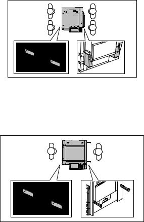
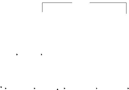
4.1 |
Installation of FAX Unit ........................................................................................................ |
4-1 |
|
|
4.2 |
Country/Region Code .......................................................................................................... |
4-2 |
|
5. |
FIRMWARE UPDATING ............................................................................................... |
5-1 |
||
© 2006 - 2011 TOSHIBA TEC CORPORATION All rights reserved |
GD-1210/1250/1270/1160/1260 |
|
CONTENTS |
1
GD-1210/1250/1270/1160/1260 |
© 2006 - 2011 TOSHIBA TEC CORPORATION All rights reserved |
CONTENTS |
|
2

1. |
ERROR CODES |
|
1 |
2. |
SELF-DIAGNOSIS MODE |
|
2 |
3. |
TROUBLESHOOTING |
|
3 |
4. |
PRECAUTIONS FOR INSTALLATION OF FAX |
|
UNIT |
|
4 |
5. |
FIRMWARE UPDATING |
|
5 |
1. |
ERROR CODES |
|
1.1 Transmission/Reception Journal and Error Code List |
1 |
|
|
||
The transmission journal is shown below. The error code list and status code list are available in the fol- |
|
|
lowing pages. The reception journal is output in the same form. |
|
|
TRANSMISSION JOURNAL |
|
TIME |
|
:MM-DD-YY TIME |
|||||
|
|
|
|
|
TEL NO.1 |
: XXXXXXXXX |
|||
|
|
|
|
|
TEL NO.2 |
: XXXXXXXXX |
|||
|
|
|
|
|
NAME |
|
: X X X X X X X |
||
NO. FILE NO. DATE |
TIMED |
DURATION |
PGS |
TO |
DEPT |
MODE |
STATUS |
||
001 001 |
12.01 |
09:00 |
00:55 |
2 |
ABCDG |
|
|
3 xxx |
OK xxxx |
Status code
Error code
Fig. 1-1
© 2006 - 2011 TOSHIBA TEC CORPORATION All rights reserved |
GD-1210/1250/1270/1160/1260 |
|
ERROR CODES |
1 - 1
1)Error code list
If an error has occurred during communication, an error code is indicated below “STATUS” on the transmission/reception journal.
Take the appropriate action referring to the following list.
Error code |
Content |
Situation and corrective action |
0000 |
Normal |
|
0012 |
Original jam |
Remove the jamming document and retransmit it. |
0013 |
Door is open |
Close the doors securely and retransmit the document. |
0020 |
Power failure |
A power failure occurred during transmission or reception, and |
|
|
the transmission/reception data were lost. Attempt the trans- |
|
|
mission/reception again. |
0030 |
Stop by paper jam during the |
Remove the jamming paper and transmit it. |
|
direct transmission |
|
0033 |
Polling error |
Polling was not performed because the polling document was |
|
|
not found or the security codes were mismatched. Check the |
|
|
polling document or security code on the other side and |
|
|
attempt the polling again. |
0042 |
Memory full |
The memory became full a memory abnormality occurred dur- |
|
|
ing reception. (The pages normally received are printed out.) |
|
|
Check the remaining memory space or memory status, and |
|
|
attempt the reception again. |
0050 |
Line is busy |
Transmission is not made because the line is busy. Attempt |
|
|
the transmission again. As the number of the redialings is |
|
|
increased, the possibility for successful transmission is |
|
|
increased. |
0053 |
Security mismatch in relay or mail |
Check your security code and system password of the other |
|
box transmission |
side as well as your own. |
00B0 |
Initial signal not detected |
NSF/DIS cannot be detected. Check the receiver and attempt |
|
|
the transmission again. |
00B1 |
Terminal constants not compati- |
DIS/NSF that cannot be handled by the sender was received. |
|
ble |
The receiver received NSS/DCS other than those declared by |
|
|
DIS/NSF. Check the transmission/reception functions, and |
|
|
attempt the communication again. |
00B2 |
Reception of DCN (Phase B) |
DCN was received in the phase B. |
|
|
|
00B3 |
DCS/DTC not detected |
DCS/DTC cannot be detected. |
|
|
|
00B4 |
Training error |
The sender performed fall-back but the transmission was not |
|
|
made. After the reception of FTT, the receiver received a time- |
|
|
out or DCN. Adjust the transmitter attenuator, link equalizer, |
|
|
etc. and retry the communication. |
00B5 |
CFR not detected |
A training signal was sent out but CFR cannot be detected. |
|
|
Adjust the transmitter attenuator, link equalizer, etc. and retry |
|
|
the transmission. |
00C0 |
Image signal carrier not detected |
A carrier was not detected on the receiving side. Adjust the |
|
|
transmitter attenuator, link equalizer, etc. and retry the trans- |
|
|
mission. |
00C1 |
High speed signal not detected |
A high-speed signal was not detected on the receiving side. |
|
|
Adjust the transmitter attenuator, link equalizer, etc. and retry |
|
|
the transmission. |
00C2 |
Image signal carrier disconnected |
Carrier disconnection was detected after the image signal was |
|
|
detected. |
00C3 |
1st EOL not detected |
1st EOL was not detected after the high-speed signal was |
|
|
detected. |
00C4 |
EOL not detected |
EOL cannot be detected on the receiving side. Or decoding is |
|
|
not possible with MMR. |
GD-1210/1250/1270/1160/1260 |
© 2006 - 2011 TOSHIBA TEC CORPORATION All rights reserved |
|
ERROR CODES |
|
|
1 - 2

Error code |
Content |
Situation and corrective action |
00D0 |
Post message not detected |
A post message cannot be detected. Retry the communica- |
|
|
tion. MCF, RTP, RTN, PIN and PIP cannot be detected on the |
|
|
sending side. MPS, EOM and EOP cannot be detected on the |
|
|
receiving side. |
00D1 |
Reception of DCN |
DCN was received. |
|
|
|
00D2 |
Poor image quality |
Quality of the received image is poor. Retry the transmission. |
|
|
|
00E8 |
HDD error |
Hardware is defective. |
|
|
|
00F0 |
Software trouble |
Software is defective. |
|
|
|
00F1 |
Hardware noise |
Hardware is defective. |
|
|
|
1 |
2) Status code list
Mode |
Transmission speed |
Resolution |
Encoding system |
0 |
2400 |
8 x 3.85 |
MH |
|
|
|
|
1 |
4800 |
8 x 7.7 |
MR |
|
|
|
|
2 |
7200 |
8 x 15.4 |
MMR |
|
|
|
|
3 |
9600 |
|
JBIG |
|
|
|
|
4 |
12000 |
16 x 15.4 |
|
|
|
|
|
5 |
14400 |
|
|
|
|
|
|
6 |
V.34 |
|
|
|
|
|
|
7 |
|
|
|
|
|
|
|
8 |
|
300 x 300 |
|
|
|
|
|
9 |
|
|
|
|
|
|
|
A |
|
|
|
|
|
|
|
B |
|
|
|
|
|
|
|
C |
|
|
|
|
|
|
|
D |
|
|
|
|
|
|
|
E |
|
|
|
|
|
|
|
F |
|
|
|
|
|
|
|
[Example of the indication of a status code]
522
 MMR (encoding system) 8 x 15.4 (resolution)
14400 (transmission speed)
For the combination of 14400 bps, 8x15.4 and MMR, as shown above, a status of “522” is indicate.
© 2006 - 2011 TOSHIBA TEC CORPORATION All rights reserved |
GD-1210/1250/1270/1160/1260 |
|
ERROR CODES |
1 - 3
1.2Error Messages
Error messages are not displayed for the background jobs (memory transmission and memory reception). See the reception/transmission report for the details of the errors.
If an original jam during the direct transmission or recording paper jam during printing occurred, error messages are displayed like when original jam occurred in the equipment.
Error messages and corrective actions
Error |
Symptom |
Message |
Remarks |
|
|
|
|
Memory full |
Communication was interrupted |
Memory |
Message displayed only during |
|
because the memory became full. |
overflow |
the memory input. |
|
|
|
It is not displayed during the |
|
|
|
memory reception. |
|
|
|
|
Line is busy |
Redialing was attempted for the |
|
Job information is stored in the |
|
specified number of times but the |
|
memory when the final retry is |
|
line is still busy. |
|
finished. |
|
|
|
|
Initial signal not |
DIS is not detected. |
Communication |
|
detected |
|
error |
|
|
|
|
|
Terminal constants |
Received DIS unable to be han- |
|
|
not compatible |
dled. |
|
|
|
Received DCS which is beyond |
|
|
|
the capability of the receiver. |
|
|
|
|
|
|
Training error |
Fall-back is not made success- |
Communication |
|
|
fully. |
error |
|
|
Became time-out after FTT was |
|
|
|
sent out. |
|
|
|
|
|
|
CFR not detected |
CFR (FTT) is not detected. |
Communication |
|
|
|
error |
|
|
|
|
|
Image signal car- |
Image signal carrier cannot be |
|
|
rier not detected |
detected. |
|
|
|
|
|
|
Image signal not |
High-speed signal cannot be |
|
|
detected |
received by the receiver. |
|
|
|
|
|
|
EOL time-out |
EOL timer exceeded by 13 sec- |
|
|
|
onds |
|
|
|
|
|
|
Post message not |
Post message is not detected. |
Communication |
|
detected |
|
error |
|
|
|
|
|
Poor image quality |
TX: Received RTN/PIN/ERR |
Communication |
|
|
RX: Transmitted RTN/PIN/ERR |
error |
|
|
|
|
|
Software overdrive |
WDT communication terminated |
Communication |
|
|
due to software overdrive |
error |
|
|
|
|
|
Hardware noise |
Communication terminated due to |
Communication |
|
|
software overdrive caused by |
error |
|
|
hardware noise |
|
|
|
|
|
|
GD-1210/1250/1270/1160/1260 |
© 2006 - 2011 TOSHIBA TEC CORPORATION All rights reserved |
ERROR CODES |
|
1 - 4
2. SELF-DIAGNOSIS MODE
There are two types of the self-diagnosis mode for the FAX operation.
• Test mode (03), adjustment mode (05) and setting mode (08): Some items are added to the test
mode (03), adjustment mode (05) and setting mode (08) of the self-diagnosis function when the |
|
optional FAX unit is installed. |
|
|
|
• FAX function mode (13) and FAX clearing mode (1*): These two modes are newly added to the |
2 |
machine when the FAX unit is installed. Started up by turning ON the power while pressing the spec- |
|
ified keys are being pressed. |
|
|
|
The followings are the modes which are added to (or extend) the PPC self-diagnosis function.
Mode |
For start |
Function |
|
Display |
|
|
|
|
|
Test Mode |
[0]+[3]+[POWER] |
Output check (modem test, dialing |
100% |
C Test Mode |
|
|
test, CML test) |
|
|
|
|
|
|
|
Adjustment Mode |
[0]+[5]+[POWER] |
Adjustment of the various items |
100% |
A Test Mode |
|
|
|
|
|
Setting Mode |
[0]+[8]+[POWER] |
Setting the destination |
100% D Test Mode |
|
|
|
|
|
|
FAX Function Mode |
[1]+[3]+[POWER] |
Setting functions of the various |
100% |
F Test Mode |
|
|
items |
|
|
|
|
|
|
|
FAX Clearing Mode |
[1]+[*]+[POWER] |
Initialization of the various memory |
100% |
CL Test Mode |
|
|
areas |
|
|
|
|
(user registration area, system set- |
|
|
|
|
ting area, image data area) |
|
|
|
|
|
|
|
Trace List Output |
Digital keys on the list output |
Outputs the protocol trace list, |
USER FUNCTIONS |
|
Mode |
screen (without entering the |
dump list and function setting list |
|
|
|
self-diagnostic mode) |
|
|
|
|
|
|
|
|
Trace List Output |
Operating from the screen for |
Outputs the protocol trace list, |
- |
|
Mode |
Service UI (without entering |
dump list and function setting list |
|
|
|
the self-diagnostic mode) |
|
|
|
|
|
|
|
|
To enter the desired mode, turn the power ON while pressing two digital keys designated to each mode (e.g. [0] and [5]) simultaneously.
Notes:
•To finish the self-diagnosis mode, make sure to turn the power OFF and then back ON.
When the equipment is started in one of the self-diagnosis modes, the equipment is occupied by the mode until the power is turned OFF. In this case, the recovery processing for the FAX operation is not performed.
•Faxes received automatically during the self-diagnosis mode may not be printed out. Be sure to disconnect the modular code from the line connectors (LINE1, LINE2) of the equipment before starting the self-diagnosis mode. Also, be sure to finish the self-diagnosis mode by turning the power OFF and back ON before connecting the modular code.
•The trace list output mode can be used by operating from the Service UI screen for models in which Service UI is embedded. For details of Service UI, refer to the Service Manual of the MFP.
© 2006 - 2011 TOSHIBA TEC CORPORATION All rights reserved |
GD-1210/1250/1270/1160/1260 |
|
SELF-DIAGNOSIS MODE |
2 - 1
11/10
2.1Test Mode (03)
The modem test output, dialing test output and CML test output are performed in the Test Mode (03).
1)Modem test / CML test [Operation procedure]
[CLEAR]
[0] [3]  [FAX]
[FAX] ([FAX])
  [Digital key]
  [START]
 Operation started
  [POWER] OFF
[POWER] (Switch line 1 and 2) |
(Code) |
(End) |
Fig. 2-1
2)Dialing test [Operation procedure]
[0] [3] |
|
|
|
[FAX] |
|
|
|
([FAX]) |
|
|
|
|
|
|
|
|
|
|
|||||
|
|
|
|
|
|
|
|
|
|
|
|
|
|
|
|
||||||||
[POWER] |
|
(Switch line 1 and 2) |
|
|
|
|
|
|
|
|
|
||||||||||||
|
|
|
|
|
|
|
|
|
|
|
|
|
|
|
|
|
|
|
|
|
|
||
|
|
|
|
|
|
|
|
|
|
|
|
|
|
|
|
|
|
|
|
|
|
|
|
|
|
|
|
|
|
|
|
|
|
[CLEAR] |
|
|
|
|
|
|
|
|
|
|
|||
|
|
|
|
|
|
|
|
|
|
|
|
|
|
|
|
|
|
|
|
||||
|
|
|
|
|
|
|
|
|
|
|
|
|
|
|
|
|
|
|
|
||||
|
|
|
|
[Digital key] |
|
|
[START] |
|
|
|
|
|
[Digital key] |
|
[START] |
|
|
[POWER] OFF |
|||||
|
|
|
|
|
|
|
|
|
|
|
|
|
|
||||||||||
|
|
|
|
|
|
|
|
|
|
|
|
|
|
||||||||||
|
|
|
|
(Code) |
|
|
|
|
|
|
|
|
|
|
[START] |
|
|
|
|
|
(End) |
||
|
|
|
|
|
|
|
|
|
|
|
|
|
|
|
|
|
|
|
|
|
|
|
|
|
|
|
|
|
|
|
|
|
|
|
|
|
|
|
|
|
|
|
|
|
|
|
|
|
|
|
|
|
|
|
|
|
|
|
|
|
|
|
|
Fig. 2-2 |
|
|
|
|
|
||
GD-1210/1250/1270/1160/1260 |
© 2006 - 2011 TOSHIBA TEC CORPORATION All rights reserved |
SELF-DIAGNOSIS MODE |
|
2 - 2

Test code list |
|
|
||
Code |
Element |
Test |
|
|
03-301 |
FAX |
Modem test 2100 Hz |
|
|
03-302 |
FAX |
Modem test 14.4 kbps (V.17) |
|
|
03-303 |
FAX |
Modem test 9.6 kbps (V.29) |
|
|
03-304 |
FAX |
Modem test 4.8 kbps (V.27) |
2 |
|
03-305 |
FAX |
Modem test 300 BPS |
||
|
||||
03-306 |
FAX |
Modem test 1850 Hz |
|
|
03-307 |
FAX |
Modem test 1650 Hz |
|
|
03-308 |
FAX |
Modem test 1100 Hz |
|
|
03-309 |
FAX |
Modem test 462 Hz |
|
|
03-310 |
FAX |
Modem test 1300 Hz |
|
|
03-311 |
FAX |
Modem test 33.6 kbps (V.34) |
|
|
03-312 |
FAX |
Modem test 28.8 kbps (V.34) |
|
|
03-313 |
FAX |
Modem test 24.0 kbps (V.34) |
|
|
03-314 |
FAX |
Modem test 16.8 kbps (V.34) |
|
|
03-315 |
FAX |
Dialing test 10 PPS (Tested with the digital keys) |
|
|
|
|
(The dial number corresponding to the key which was pressed is kept outputting on the |
|
|
|
|
circuit. The pressed key is displayed on the control panel.) |
|
|
03-317 |
FAX |
Dialing test PB (Tested with the digital keys) |
|
|
|
|
(The dial number corresponding to the key which was pressed is kept outputting on the |
|
|
|
|
circuit. The pressed key is displayed on the control panel.) |
|
|
03-318 |
FAX |
Modem test 12.0 kbps (V.17) |
|
|
03-319 |
FAX |
Modem test 7.2 kbps (V.29) |
|
|
03-320 |
FAX |
Modem test 2.4 kbps (V.27ter) |
|
|
03-321 |
FAX |
Performs Read/Write test to all the image memories mounted on the FAX board and |
|
|
|
|
displays the test result (status) on the control panel. Also, detects automatically whether |
|
|
|
|
the extended memory is mounted or not. |
|
|
03-322 |
FAX |
CML test: Turning ON the CML relay |
|
|
© 2006 - 2011 TOSHIBA TEC CORPORATION All rights reserved |
GD-1210/1250/1270/1160/1260 |
|
SELF-DIAGNOSIS MODE |
2 - 3
11/10

2.2Adjustment Mode (05)
Parameter setting for the FAX image processing is performed in the Adjustment Mode (05).
1)Setting parameters for the FAX image processing [Operation procedure]
|
|
|
|
|
|
|
|
|
|
|
[ENTER] |
|
|
||
[0] [5] |
|
|
[Digital key] |
|
[START] |
|
|
[Digital key] |
|
|
|
or |
|
|
[POWER] OFF |
|
|
|
|
|
|
|
|
|
|
||||||
[POWER] |
|
(Code) |
|
|
|
|
*[FC] |
|
[INTERRUPT] |
|
|||||
|
|
|
|
|
|
|
[OK] *1 |
|
|||||||
|
|
|
|
|
(Key in the adjustment value) |
|
|
|
|||||||
|
|
|
|
|
|
(Save the value in the RAM) |
|||||||||
|
|
|
|
|
[CANCEL] |
|
[CLEAR] |
|
|||||||
|
|
|
|
|
|
|
|||||||||
|
|
|
|
|
|
|
|
(In case the value is corrected) |
|
||||||
Fig. 2-3
*“-” can be entered with the [FC] button.
*1: For e-STUDIO2040C/2540C/3040C/3540C/4540C, e-STUDIO5540C/6540C/6550C, e- STUDIO206L/256/306/356/456 and e-STUDIO556/656/756/856.
GD-1210/1250/1270/1160/1260 |
© 2006 - 2011 TOSHIBA TEC CORPORATION All rights reserved |
SELF-DIAGNOSIS MODE |
|
2 - 4
11/12

Adjustment codes for the image processing parameters |
|
|
|
|
|
|||
|
Code |
|
|
|
Image |
|
Accept- |
|
Code |
Element |
Adjustment item |
Mode |
quality |
Default |
able |
|
|
*1 |
|
|||||||
|
|
|
|
mode |
|
value |
|
|
|
|
|
|
|
|
|
||
05- |
05- |
Density |
Adjustment of the threshold value for the |
FAX |
Text |
125 |
0 to 255 |
|
700 |
7534 |
|
binarization |
|
|
|
|
|
|
|
|
Center value |
|
|
|
|
|
05- |
|
Density |
Adjustment of the threshold value for the |
FAX |
Text |
20 |
0 to 255 |
2 |
701 |
|
|
binarization |
|
|
|
|
|
|
|
|
Lighter step value |
|
|
|
|
|
05- |
|
Density |
Adjustment of the threshold value for the |
FAX |
Text |
20 |
0 to 255 |
|
702 |
|
|
binarization |
|
|
|
|
|
|
|
|
Darker step value |
|
|
|
|
|
05- |
05- |
Density |
Manual-density fine adjustment |
FAX |
Photo |
128 |
0 to 255 |
|
710 |
7535 |
|
Error diffusion, Center value |
|
|
|
|
|
05- |
05- |
Density |
Manual-density fine adjustment |
FAX |
Text/ |
128 |
0 to 255 |
|
714 |
7533 |
|
Error diffusion, Center value |
|
Photo |
|
|
|
05- |
|
Density |
Manual-density fine adjustment |
FAX |
Photo |
20 |
0 to 255 |
|
715 |
|
|
Error diffusion, Lighter step value |
|
|
|
|
|
05- |
|
Density |
Manual-density fine adjustment |
FAX |
Text/ |
20 |
0 to 255 |
|
719 |
|
|
Error diffusion, Lighter step value |
|
Photo |
|
|
|
05- |
|
Density |
Manual-density fine adjustment |
FAX |
Photo |
20 |
0 to 255 |
|
720 |
|
|
Error diffusion, Darker step value |
|
|
|
|
|
05- |
|
Density |
Manual-density fine adjustment |
FAX |
Text/ |
20 |
0 to 255 |
|
724 |
|
|
Error diffusion, Darker step value |
|
Photo |
|
|
|
05- |
05- |
Density |
Auto-density fine adjustment |
FAX |
Photo |
128 |
0 to 255 |
|
725 |
7543 |
|
Error diffusion |
|
|
|
|
|
05- |
05- |
Density |
Auto-density fine adjustment |
FAX |
Text/ |
128 |
0 to 255 |
|
729 |
7542 |
|
Error diffusion |
|
Photo |
|
|
|
*1: For e-STUDIO2040C/2540C/3040C/3540C/4540C, e-STUDIO5540C/6540C/6550C, e- STUDIO206L/256/306/356/456 and e-STUDIO556/656/756/856.
© 2006 - 2011 TOSHIBA TEC CORPORATION All rights reserved |
GD-1210/1250/1270/1160/1260 |
|
SELF-DIAGNOSIS MODE |
2 - 5
11/12

2.3Setting Mode (08)
The destination is set in the Setting Mode (08).
[Operation procedure]
|
|
|
|
|
|
[CANCEL] |
|
|
|
|
|
[ENTER] |
|
|
||||
|
|
|
|
|
|
|
|
|
|
|
|
|
||||||
|
|
|
|
|
|
|
|
|
|
|
|
|
|
|
|
|||
[0] [8] |
|
|
|
[Digital key] |
|
|
[START] |
|
|
[Digital key] |
|
|
|
|
or |
|
|
[POWER] |
|
|
|
|
|
|
|
|
|
|
|
|
|
||||||
[POWER] |
(Code) |
|
|
|
|
(Key in a value) |
|
[INTERRUPT] |
|
OFF |
||||||||
|
|
|
|
|
|
[OK] *1 |
|
|||||||||||
|
|
|
|
|
|
|
|
|
|
|
|
|
|
|
|
|
||
|
|
|
|
|
|
|
|
|
|
|
|
|
|
(Save the value in the RAM) |
||||
|
|
|
|
|
|
|
|
|
|
|
[CLEAR] |
|
|
|||||
|
|
|
|
|
|
|
|
|
|
(In case the value is corrected) |
|
|
||||||
|
|
|
|
|
|
|
|
|
|
Fig. 2-4 |
|
|
|
|
|
|
|
|
*1: For e-STUDIO2040C/2540C/3040C/3540C/4540C, e-STUDIO5540C/6540C/6550C, e- STUDIO206L/256/306/356/456 and e-STUDIO556/656/756/856.
|
|
|
|
|
|
|
|
Default value at |
|
Code |
Code |
Element |
Adjustment item |
Mode |
Image |
the |
|||
|
*1 |
|
|
|
|
|
mode |
product ship- |
|
|
|
|
|
|
|
|
|
ment |
|
|
|
|
|
|
|
|
|
|
|
|
|
|
Destination |
|
|
|
|
|
|
|
|
|
1: Asia |
2: Australia |
3: Hong Kong |
|
|
|
|
|
|
|
4: U.S.A/Canada |
5: Germany |
|
|
NA: 4 |
||
|
|
|
6: Great Britain |
7: Italy |
8: Belgium |
|
|
||
|
|
|
|
|
TW: 25 |
||||
|
|
|
9: Holland |
10: Finland |
11: Spain |
|
|
||
08- |
08- |
|
|
|
EU: 5 |
||||
FAX |
12: Austria |
13: Switzerland |
FAX |
- |
|||||
701 |
9001 |
AU: 2 |
|||||||
|
14: Sweden |
15: Denmark |
|
|
|
||||
|
|
|
|
|
|
AS: 1 |
|||
|
|
|
16: Norway |
17: Portugal |
18: France |
|
|
||
|
|
|
|
|
C: 1 |
||||
|
|
|
19: Greece |
20: Poland |
21: Hungary |
|
|
||
|
|
|
|
|
|
||||
|
|
|
22: Czech Rep. 23: Turkey |
|
|
|
|
||
|
|
|
24: South Africa |
25: Taiwan |
|
|
|
|
|
|
|
|
|
|
|
|
|
|
|
*1: For e-STUDIO2040C/2540C/3040C/3540C/4540C, e-STUDIO5540C/6540C/6550C, e- STUDIO206L/256/306/356/456 and e-STUDIO556/656/756/856.
GD-1210/1250/1270/1160/1260 |
© 2006 - 2011 TOSHIBA TEC CORPORATION All rights reserved |
SELF-DIAGNOSIS MODE |
|
2 - 6
11/12
2.4Function Mode (13)
Various functions are set in the Function Mode (13).
1) |
Procedure to set the functions |
|
|
|
||
|
Key in a code and change the set value. |
|
|
|
||
|
[Operation procedure] |
|
|
|
2 |
|
|
|
|
|
|
|
|
|
|
|
[CANCEL] |
|
[ENTER] |
|
|
|
|
|
|
|
|
|
[1] [3] |
[Digital key] |
[START] |
[Digital key] |
or |
[POWER] |
[POWER] |
(Code) |
(Key in a value) |
[INTERRUPT] |
OFF |
|
[OK] *1 |
|||||
|
|
|
|
||
|
|
|
(Save the value in the RAM) |
|
|
|
|
[CLEAR] |
|
||
|
|
(In case the value is corrected) |
|
||
|
|
Fig. 2-5 |
|
|
|
*1: For e-STUDIO2040C/2540C/3040C/3540C/4540C, e-STUDIO5540C/6540C/6550C, e- STUDIO206L/256/306/356/456 and e-STUDIO556/656/756/856.
2)Procedure to confirm the set value [Operation procedure]
|
|
|
|
|
|
|
[ENTER] |
|
|
|
[1] [3] |
|
|
[Digital key] |
|
[START] |
|
or |
|
|
[POWER] OFF |
|
|
|
|
|
|
|||||
[POWER] |
(Code) |
|
|
|
[INTERRUPT] |
|
||||
|
|
|
[OK] *1 |
|
||||||
|
|
|
|
|
|
|
|
|||
(Set value cannot be changed)
Fig. 2-6
*1: For e-STUDIO2040C/2540C/3040C/3540C/4540C, e-STUDIO5540C/6540C/6550C, e- STUDIO206L/256/306/356/456 and e-STUDIO556/656/756/856.
© 2006 - 2011 TOSHIBA TEC CORPORATION All rights reserved |
GD-1210/1250/1270/1160/1260 |
|
SELF-DIAGNOSIS MODE |
2 - 7
11/12
Function code list (100-999)
100-299 Adjustment within the dialing standards
Code |
Adjust- |
Function |
|
Setting |
|
|
|
|
Default |
|
|
|
|
|
ment |
|
|
|
|
|
|
|
|
|
|
|
|||
|
ASM |
AUS |
HKG |
USA |
|
DEU |
GBR |
ITA |
BEL |
NDL |
||||
|
|
|
|
|
||||||||||
13- |
DTC fre- |
Sets the dial |
0: |
300-600 Hz |
0 |
0 |
0 |
0 |
|
1 |
1 |
1 |
1 |
1 |
100 |
quency |
tone frequency |
1: |
300-650 Hz |
|
|
|
|
|
|
|
|
|
|
|
(PSTN) |
to be detected |
2: |
390-550 Hz |
|
|
|
|
|
|
|
|
|
|
|
(Line 1) |
for the PSTN. |
3: |
400-450 Hz |
|
|
|
|
|
|
|
|
|
|
|
|
|
4: |
350-480 Hz |
|
|
|
|
|
|
|
|
|
|
|
|
|
5: |
300-500 Hz |
|
|
|
|
|
|
|
|
|
|
13- |
DTC |
Sets the time |
0: |
2 sec |
0 |
0 |
0 |
3 |
|
2 |
2 |
2 |
2 |
2 |
101 |
time |
for a tone |
1: |
800 ms |
|
|
|
|
|
|
|
|
|
|
|
(PSTN) |
sounds to be |
2: |
400 ms |
|
|
|
|
|
|
|
|
|
|
|
(Line 1) |
determined as |
3: |
1 sec |
|
|
|
|
|
|
|
|
|
|
|
|
dial tone for the |
4: |
1.3 sec |
|
|
|
|
|
|
|
|
|
|
|
|
PSTN. |
5: |
1.8 sec |
|
|
|
|
|
|
|
|
|
|
|
|
|
6: |
2.5 sec |
|
|
|
|
|
|
|
|
|
|
|
|
|
7: |
500 ms |
|
|
|
|
|
|
|
|
|
|
13- |
LCC |
Sets the inter- |
0: |
OFF |
0 |
0 |
0 |
3 |
|
2 |
2 |
2 |
2 |
2 |
102 |
allowed |
ruption time for |
1: |
50 ms |
|
|
|
|
|
|
|
|
|
|
|
gaps |
the PSTN to be |
2: |
100 ms |
|
|
|
|
|
|
|
|
|
|
|
(PSTN) |
ignored during |
3: |
200 ms |
|
|
|
|
|
|
|
|
|
|
|
(Line 1) |
LCC. |
|
|
|
|
|
|
|
|
|
|
|
|
13- |
DTC |
Sets the inter- |
0: OFF |
1 |
1 |
1 |
1 |
|
1 |
1 |
1 |
1 |
1 |
|
103 |
allowed |
ruption time for |
1: |
320 ms |
|
|
|
|
|
|
|
|
|
|
|
gaps |
PSTN to be |
2: |
160 ms |
|
|
|
|
|
|
|
|
|
|
|
(PSTN) |
ignored during |
3: |
240 ms |
|
|
|
|
|
|
|
|
|
|
|
(Line 1) |
DTC. |
|
|
|
|
|
|
|
|
|
|
|
|
13- |
DTC/ |
Selects which is |
0: BZT |
2 |
2 |
2 |
2 |
|
2 |
2 |
2 |
2 |
2 |
|
104 |
LCC for |
to be used for |
|
(DTC/LCC) |
|
|
|
|
|
|
|
|
|
|
|
PSTN |
the PSTN, DTC |
1: LCC 5 sec |
|
|
|
|
|
|
|
|
|
|
|
|
(Line 1) |
or LCC. |
2: DTC only |
|
|
|
|
|
|
|
|
|
|
|
|
|
|
3: FRN |
|
|
|
|
|
|
|
|
|
|
|
|
|
|
|
(DTC/LCC) |
|
|
|
|
|
|
|
|
|
|
|
|
|
4: DTC (JPN) |
|
|
|
|
|
|
|
|
|
|
|
|
|
|
5: NO |
|
|
|
|
|
|
|
|
|
|
|
|
|
|
|
DTC&LCC |
|
|
|
|
|
|
|
|
|
|
13- |
DTC |
Sets how long |
0: |
20 sec |
0 |
0 |
0 |
1 |
|
1 |
1 |
1 |
1 |
1 |
105 |
time out |
the dial tone |
1: |
10 sec |
|
|
|
|
|
|
|
|
|
|
|
(PSTN) |
detection is per- |
2: |
8 sec |
|
|
|
|
|
|
|
|
|
|
|
(Line 1) |
formed. |
3: |
15 sec |
|
|
|
|
|
|
|
|
|
|
|
|
|
4: |
3.3 sec |
|
|
|
|
|
|
|
|
|
|
13- |
DTC fre- |
Sets the dial |
0: |
300-600 Hz |
0 |
0 |
0 |
0 |
|
1 |
1 |
1 |
1 |
1 |
106 |
quency |
tone frequency |
1: |
300-650 Hz |
|
|
|
|
|
|
|
|
|
|
|
(PABX) |
to be detected |
2: |
390-550 Hz |
|
|
|
|
|
|
|
|
|
|
|
(Line 1) |
for PABX. |
3: |
400-450 Hz |
|
|
|
|
|
|
|
|
|
|
|
|
|
4: |
350-480 Hz |
|
|
|
|
|
|
|
|
|
|
|
|
|
5: |
300-500 Hz |
|
|
|
|
|
|
|
|
|
|
13- |
DTC |
Sets the time |
0: 2 sec |
0 |
0 |
0 |
6 |
|
2 |
2 |
2 |
2 |
2 |
|
107 |
time |
for a tone |
1: 800 ms |
|
|
|
|
|
|
|
|
|
|
|
|
(PABX) |
sounds to be |
2: 400 ms |
|
|
|
|
|
|
|
|
|
|
|
|
(Line 1) |
determined as |
3: 1 sec |
|
|
|
|
|
|
|
|
|
|
|
|
|
dial tone for the |
4: 1.3 sec |
|
|
|
|
|
|
|
|
|
|
|
|
|
PABX. |
5: 1.8 sec |
|
|
|
|
|
|
|
|
|
|
|
|
|
|
6: 2.5 sec |
|
|
|
|
|
|
|
|
|
|
|
|
|
|
7: 150 ms |
|
|
|
|
|
|
|
|
|
|
|
GD-1210/1250/1270/1160/1260 |
© 2006 - 2011 TOSHIBA TEC CORPORATION All rights reserved |
SELF-DIAGNOSIS MODE |
|
2 - 8
11/10

|
|
|
|
|
|
|
Default |
|
|
|
|
|
|
|
Code |
|
FIN |
ESP |
AUT |
CHE |
SWE |
DNK |
NOR |
PRT |
FRA |
GRC |
POL |
HUN |
CZE |
TUR |
ZAF |
TWN |
|
1 |
1 |
1 |
1 |
1 |
1 |
1 |
1 |
1 |
1 |
1 |
1 |
1 |
0 |
0 |
1 |
13- |
|
|
|
|
|
|
|
|
|
|
|
|
|
|
|
|
100 |
|
|
|
|
|
|
|
|
|
|
|
|
|
|
|
|
2 |
2 |
2 |
2 |
2 |
2 |
2 |
2 |
2 |
2 |
2 |
2 |
2 |
2 |
0 |
0 |
2 |
13- |
|
|
|
|
|
|
|
|
|
|
|
|
|
|
|
|
101 |
2 |
2 |
2 |
2 |
2 |
2 |
2 |
2 |
2 |
2 |
2 |
2 |
2 |
0 |
0 |
2 |
13- |
|
|
|
|
|
|
|
|
|
|
|
|
|
|
|
|
102 |
1 |
1 |
1 |
1 |
1 |
1 |
1 |
1 |
1 |
1 |
1 |
1 |
1 |
1 |
1 |
1 |
13- |
|
|
|
|
|
|
|
|
|
|
|
|
|
|
|
|
103 |
2 |
2 |
2 |
2 |
2 |
2 |
2 |
2 |
2 |
2 |
2 |
2 |
2 |
2 |
2 |
2 |
13- |
|
|
|
|
|
|
|
|
|
|
|
|
|
|
|
|
104 |
1 |
1 |
1 |
1 |
1 |
1 |
1 |
1 |
1 |
1 |
1 |
1 |
1 |
0 |
0 |
1 |
13- |
|
|
|
|
|
|
|
|
|
|
|
|
|
|
|
|
105 |
1 |
1 |
1 |
1 |
1 |
1 |
1 |
1 |
1 |
1 |
1 |
1 |
1 |
0 |
0 |
1 |
13- |
|
|
|
|
|
|
|
|
|
|
|
|
|
|
|
|
106 |
2 |
2 |
2 |
2 |
2 |
2 |
2 |
2 |
2 |
2 |
2 |
2 |
2 |
0 |
0 |
2 |
13- |
|
|
|
|
|
|
|
|
|
|
|
|
|
|
|
|
107 |
© 2006 - 2011 TOSHIBA TEC CORPORATION All rights reserved |
GD-1210/1250/1270/1160/1260 |
|
SELF-DIAGNOSIS MODE |
2 - 9
11/10
Code |
Adjust- |
Function |
|
Setting |
|
|
|
|
Default |
|
|
|
|
|
ment |
|
ASM |
AUS |
HKG |
USA |
|
DEU |
GBR |
ITA |
BEL |
NDL |
|||
|
|
|
|
|
||||||||||
|
|
|
|
|
|
|
|
|
|
|
|
|
|
|
13- |
LCC |
Sets the inter- |
0: OFF |
0 |
0 |
0 |
0 |
|
3 |
3 |
3 |
3 |
3 |
|
108 |
allowed |
ruption time for |
1: |
50 ms |
|
|
|
|
|
|
|
|
|
|
|
gaps |
the PABX to be |
2: |
100 ms |
|
|
|
|
|
|
|
|
|
|
|
(PABX) |
ignored during |
3: |
200 ms |
|
|
|
|
|
|
|
|
|
|
|
(Line 1) |
LCC. |
|
|
|
|
|
|
|
|
|
|
|
|
|
|
|
|
|
|
|
|
|
|
|
|
|
|
|
13- |
DTC |
Sets the inter- |
0: OFF |
1 |
1 |
1 |
1 |
|
1 |
1 |
1 |
1 |
1 |
|
109 |
allowed |
ruption time for |
1: |
320 ms |
|
|
|
|
|
|
|
|
|
|
|
gaps |
the PABX to be |
2: |
160 ms |
|
|
|
|
|
|
|
|
|
|
|
(PABX) |
ignored during |
3: |
240 ms |
|
|
|
|
|
|
|
|
|
|
|
(Line 1) |
DTC. |
|
|
|
|
|
|
|
|
|
|
|
|
13- |
DTC/ |
Selects which is |
0: BZT |
5 |
5 |
5 |
5 |
|
5 |
5 |
5 |
5 |
5 |
|
110 |
LCC for |
to be used for |
|
(DTC/LCC) |
|
|
|
|
|
|
|
|
|
|
|
PABX |
the PABX, DTC |
1: LCC 5 sec |
|
|
|
|
|
|
|
|
|
|
|
|
(Line 1) |
or LCC. |
2: DTC only |
|
|
|
|
|
|
|
|
|
|
|
|
|
|
3: FRN |
|
|
|
|
|
|
|
|
|
|
|
|
|
|
|
(DTC/LCC) |
|
|
|
|
|
|
|
|
|
|
|
|
|
4: DTC (JPN) |
|
|
|
|
|
|
|
|
|
|
|
|
|
|
5: NO |
|
|
|
|
|
|
|
|
|
|
|
|
|
|
|
DTC&LCC |
|
|
|
|
|
|
|
|
|
|
|
|
|
|
|
|
|
|
|
|
|
|
|
|
|
13- |
DTC |
Sets how long |
0: |
20 sec |
0 |
0 |
0 |
1 |
|
1 |
1 |
1 |
1 |
1 |
111 |
time out |
the dial tone |
1: |
10 sec |
|
|
|
|
|
|
|
|
|
|
|
(PABX) |
detection is per- |
2: |
8 sec |
|
|
|
|
|
|
|
|
|
|
|
(Line 1) |
formed. |
3: |
15 sec |
|
|
|
|
|
|
|
|
|
|
|
|
|
4: |
3.3 sec |
|
|
|
|
|
|
|
|
|
|
13- |
BTC fre- |
Sets the busy |
0: Not |
0 |
0 |
0 |
1 |
|
1 |
1 |
1 |
1 |
1 |
|
112 |
quency |
tone frequency |
|
detected |
|
|
|
|
|
|
|
|
|
|
|
(Line 1) |
to be detected |
1: |
300-600 Hz |
|
|
|
|
|
|
|
|
|
|
|
|
for the PSTN |
2: |
350-550 Hz |
|
|
|
|
|
|
|
|
|
|
|
|
and PABX. |
3: |
300-500 Hz |
|
|
|
|
|
|
|
|
|
|
|
|
|
4: |
300-700 Hz |
|
|
|
|
|
|
|
|
|
|
|
|
|
|
|
|
|
|
|
|
|
|
|
|
|
13- |
Dial T1 |
Sets the time to |
0: |
60 sec |
0 |
3 |
0 |
3 |
|
2 |
2 |
2 |
2 |
2 |
116 |
timer |
wait for a |
1: |
35 sec |
|
|
|
|
|
|
|
|
|
|
|
(Line 1) |
response from |
2: |
90 sec |
|
|
|
|
|
|
|
|
|
|
|
|
the receiver |
3: |
55 sec |
|
|
|
|
|
|
|
|
|
|
|
|
after dialing is |
4: |
115 sec |
|
|
|
|
|
|
|
|
|
|
|
|
completed. |
|
|
|
|
|
|
|
|
|
|
|
|
13- |
Dial stop |
In case of T1 |
0: OFF |
0 |
0 |
0 |
1 |
|
0 |
0 |
0 |
0 |
0 |
|
117 |
after T1 |
time-out (no |
1: |
ON |
|
|
|
|
|
|
|
|
|
|
|
|
response from |
|
|
|
|
|
|
|
|
|
|
|
|
|
|
the receiver) |
|
|
|
|
|
|
|
|
|
|
|
|
|
|
during the auto- |
|
|
|
|
|
|
|
|
|
|
|
|
|
|
matic dialing, |
|
|
|
|
|
|
|
|
|
|
|
|
|
|
redialing is not |
|
|
|
|
|
|
|
|
|
|
|
|
|
|
performed and |
|
|
|
|
|
|
|
|
|
|
|
|
|
|
it is determined |
|
|
|
|
|
|
|
|
|
|
|
|
|
|
that the trans- |
|
|
|
|
|
|
|
|
|
|
|
|
|
|
mission is ter- |
|
|
|
|
|
|
|
|
|
|
|
|
|
|
minated due to |
|
|
|
|
|
|
|
|
|
|
|
|
|
|
error. |
|
|
|
|
|
|
|
|
|
|
|
|
13- |
CML |
Pause before |
0: |
0 ms |
2 |
2 |
2 |
2 |
|
2 |
2 |
2 |
2 |
2 |
122 |
make |
dialing |
1: |
10 ms |
|
|
|
|
|
|
|
|
|
|
|
time |
|
¦ |
|
|
|
|
|
|
|
|
|
|
|
|
before |
|
255:2550 ms |
|
|
|
|
|
|
|
|
|
|
|
|
dialing |
|
|
|
|
|
|
|
|
|
|
|
|
|
GD-1210/1250/1270/1160/1260 |
© 2006 - 2011 TOSHIBA TEC CORPORATION All rights reserved |
SELF-DIAGNOSIS MODE |
|
2 - 10
11/10

|
|
|
|
|
|
|
Default |
|
|
|
|
|
|
|
Code |
|
|
|
|
|
|
|
|
|
|
|
|
|
|
|
|
|
|
FIN |
ESP |
AUT |
CHE |
SWE |
DNK |
NOR |
PRT |
FRA |
GRC |
POL |
HUN |
CZE |
TUR |
ZAF |
TWN |
|
|
|
|
|
|
|
|
|
|
|
|
|
|
|
|
|
|
3 |
3 |
3 |
3 |
3 |
3 |
3 |
3 |
3 |
3 |
3 |
3 |
3 |
0 |
0 |
2 |
13- |
|
|
|
|
|
|
|
|
|
|
|
|
|
|
|
|
108 |
|
|
|
|
|
|
|
|
|
|
|
|
|
|
|
|
|
1 |
1 |
1 |
1 |
1 |
1 |
1 |
1 |
1 |
1 |
1 |
1 |
1 |
1 |
1 |
1 |
13- |
|
|
|
|
|
|
|
|
|
|
|
|
|
|
|
|
109 |
|
|
|
|
|
|
|
|
|
|
|
|
|
|
|
|
|
5 |
5 |
5 |
5 |
5 |
5 |
5 |
5 |
5 |
5 |
5 |
5 |
5 |
5 |
5 |
5 |
13- |
|
|
|
|
|
|
|
|
|
|
|
|
|
|
|
|
110 |
|
|
|
|
|
|
|
|
|
|
|
|
|
|
|
|
|
1 |
1 |
1 |
1 |
1 |
1 |
1 |
1 |
1 |
1 |
1 |
1 |
1 |
0 |
0 |
1 |
13- |
|
|
|
|
|
|
|
|
|
|
|
|
|
|
|
|
111 |
|
|
|
|
|
|
|
|
|
|
|
|
|
|
|
|
|
1 |
1 |
1 |
1 |
1 |
1 |
1 |
1 |
1 |
1 |
1 |
1 |
1 |
0 |
0 |
1 |
13- |
|
|
|
|
|
|
|
|
|
|
|
|
|
|
|
|
112 |
|
|
|
|
|
|
|
|
|
|
|
|
|
|
|
|
|
2 |
2 |
2 |
2 |
2 |
2 |
2 |
2 |
2 |
2 |
2 |
2 |
2 |
0 |
0 |
3 |
13- |
|
|
|
|
|
|
|
|
|
|
|
|
|
|
|
|
116 |
|
|
|
|
|
|
|
|
|
|
|
|
|
|
|
|
|
0 |
0 |
0 |
0 |
0 |
0 |
0 |
0 |
0 |
0 |
0 |
0 |
0 |
0 |
0 |
0 |
13- |
|
|
|
|
|
|
|
|
|
|
|
|
|
|
|
|
117 |
|
|
|
|
|
|
|
|
|
|
|
|
|
|
|
|
|
2 |
2 |
2 |
2 |
2 |
2 |
2 |
2 |
2 |
2 |
2 |
2 |
2 |
2 |
2 |
2 |
13- |
|
|
|
|
|
|
|
|
|
|
|
|
|
|
|
|
122 |
|
|
|
|
|
|
|
|
|
|
|
|
|
|
|
|
|
© 2006 - 2011 TOSHIBA TEC CORPORATION All rights reserved |
|
|
|
|
|
GD-1210/1250/1270/1160/1260 |
||||||||||
|
|
|
|
|
|
|
|
|
|
|
|
|
|
SELF-DIAGNOSIS MODE |
||
|
|
|
|
|
|
|
|
2 - 11 |
|
|
|
|
|
|
|
|
2 |
11/10
Code |
Adjust- |
Function |
|
Setting |
|
|
|
|
Default |
|
|
|
|
|
ment |
|
ASM |
AUS |
HKG |
USA |
|
DEU |
GBR |
ITA |
BEL |
NDL |
|||
|
|
|
|
|
||||||||||
|
|
|
|
|
|
|
|
|
|
|
|
|
|
|
13- |
CML |
Pause after |
0: |
0 ms |
100 |
100 |
100 |
100 |
|
100 |
100 |
100 |
100 |
100 |
123 |
hold |
dialing |
1: |
10 ms |
|
|
|
|
|
|
|
|
|
|
|
time |
|
¦ |
|
|
|
|
|
|
|
|
|
|
|
|
after |
|
255:2550 ms |
|
|
|
|
|
|
|
|
|
|
|
|
dialing |
|
|
|
|
|
|
|
|
|
|
|
|
|
|
|
|
|
|
|
|
|
|
|
|
|
|
|
|
13- |
Dial |
Sets the defini- |
0: |
Normal |
0 |
0 |
0 |
0 |
|
0 |
0 |
0 |
0 |
0 |
125 |
informa- |
tion of the DP |
1: |
Shift |
|
|
|
|
|
|
|
|
|
|
|
tion |
dial. |
2: |
Reverse |
|
|
|
|
|
|
|
|
|
|
|
(Line 1) |
Normal: n |
|
|
|
|
|
|
|
|
|
|
|
|
|
|
Shift: n+1 |
|
|
|
|
|
|
|
|
|
|
|
|
|
|
Reverse: 10-n |
|
|
|
|
|
|
|
|
|
|
|
|
|
|
n=Dial No. |
|
|
|
|
|
|
|
|
|
|
|
|
|
|
|
|
|
|
|
|
|
|
|
|
|
|
|
13- |
Internal |
When dialing is |
0: OFF |
0 |
0 |
0 |
0 |
|
1 |
1 |
0 |
0 |
0 |
|
127 |
retry |
interrupted |
1: |
ON |
|
|
|
|
|
|
|
|
|
|
|
|
because any of |
|
|
|
|
|
|
|
|
|
|
|
|
|
|
the settings for |
|
|
|
|
|
|
|
|
|
|
|
|
|
|
DTC/LCC is not |
|
|
|
|
|
|
|
|
|
|
|
|
|
|
satisfied during |
|
|
|
|
|
|
|
|
|
|
|
|
|
|
redialing, that |
|
|
|
|
|
|
|
|
|
|
|
|
|
|
redialing is |
|
|
|
|
|
|
|
|
|
|
|
|
|
|
ignored since it |
|
|
|
|
|
|
|
|
|
|
|
|
|
|
is considered |
|
|
|
|
|
|
|
|
|
|
|
|
|
|
as an internal |
|
|
|
|
|
|
|
|
|
|
|
|
|
|
retry. |
|
|
|
|
|
|
|
|
|
|
|
|
13- |
Redial- |
Sets the num- |
0: No retry |
5 |
2 |
4 |
5 |
|
3 |
4 |
3 |
3 |
5 |
|
128 |
ing |
ber of redial- |
1: |
1 redialing |
|
|
|
|
|
|
|
|
|
|
|
counter |
ings. |
¦ |
|
|
|
|
|
|
|
|
|
|
|
|
|
|
14: |
14 redial- |
|
|
|
|
|
|
|
|
|
|
|
|
|
|
ings |
|
|
|
|
|
|
|
|
|
|
|
|
|
|
|
|
|
|
|
|
|
|
|
|
|
13- |
Time for |
Sets the time |
0: |
0 sec |
4 |
2 |
2 |
4 |
|
2 |
2 |
3 |
2 |
0 |
129 |
a pause |
for a pause |
1: |
1 sec |
|
|
|
|
|
|
|
|
|
|
|
(Line 1) |
when it is |
2: |
2 sec |
|
|
|
|
|
|
|
|
|
|
|
|
inserted |
3: |
4 sec |
|
|
|
|
|
|
|
|
|
|
|
|
between the |
4: |
3.3 sec |
|
|
|
|
|
|
|
|
|
|
|
|
dial numbers. |
5: |
10 sec |
|
|
|
|
|
|
|
|
|
|
13- |
Inter- |
Sets the interval |
0: |
900 ms |
0 |
0 |
2 |
3 |
|
0 |
3 |
3 |
2 |
2 |
132 |
digit |
between digits |
1: |
550 ms |
|
|
|
|
|
|
|
|
|
|
|
pause |
for DP dialing. |
2: |
700 ms |
|
|
|
|
|
|
|
|
|
|
|
(Line 1) |
|
3: |
800 ms |
|
|
|
|
|
|
|
|
|
|
13- |
Redial- |
Sets the interval |
0: |
Default |
3 |
1 |
3 |
1 |
|
0 |
0 |
3 |
2 |
2 |
135 |
ing inter- |
between redial- |
|
(3 min) |
|
|
|
|
|
|
|
|
|
|
|
val |
ings. |
1: |
1 min |
|
|
|
|
|
|
|
|
|
|
|
(Line 1) |
|
¦ |
|
|
|
|
|
|
|
|
|
|
|
|
|
|
15: |
15 min |
|
|
|
|
|
|
|
|
|
|
GD-1210/1250/1270/1160/1260 |
© 2006 - 2011 TOSHIBA TEC CORPORATION All rights reserved |
SELF-DIAGNOSIS MODE |
|
2 - 12
11/10

|
|
|
|
|
|
|
Default |
|
POL HUN CZE TUR ZAF TWN Code |
|
|||||||
FIN |
ESP |
AUT |
CHE |
SWE |
DNK |
NOR |
PRT |
FRA |
GRC |
|
|||||||
100 |
100 |
100 |
100 |
100 |
100 |
100 |
100 |
100 |
100 |
100 |
100 |
100 |
100 |
100 |
100 |
13- |
|
|
|
|
|
|
|
|
|
|
|
|
|
|
|
|
|
123 |
|
0 |
0 |
0 |
0 |
1 |
0 |
2 |
0 |
0 |
0 |
0 |
0 |
0 |
0 |
0 |
0 |
13- |
2 |
|
|||||||||||||||||
|
|
|
|
|
|
|
|
|
|
|
|
|
|
|
|
125 |
|
0 |
0 |
1 |
0 |
0 |
1 |
1 |
0 |
0 |
0 |
0 |
0 |
0 |
0 |
0 |
0 |
13- |
|
|
|
|
|
|
|
|
|
|
|
|
|
|
|
|
|
127 |
|
3 |
3 |
1 |
4 |
5 |
4 |
9 |
3 |
5 |
4 |
3 |
3 |
3 |
5 |
5 |
2 |
13- |
|
|
|
|
|
|
|
|
|
|
|
|
|
|
|
|
|
128 |
|
2 |
2 |
2 |
0 |
2 |
2 |
2 |
1 |
2 |
4 |
4 |
4 |
4 |
4 |
4 |
4 |
13- |
|
|
|
|
|
|
|
|
|
|
|
|
|
|
|
|
|
129 |
|
0 |
1 |
3 |
3 |
2 |
2 |
2 |
2 |
0 |
3 |
3 |
0 |
0 |
0 |
0 |
0 |
13- |
|
|
|
|
|
|
|
|
|
|
|
|
|
|
|
|
|
132 |
|
0 |
2 |
2 |
2 |
1 |
0 |
0 |
1 |
3 |
3 |
3 |
3 |
3 |
3 |
3 |
2 |
13- |
|
|
|
|
|
|
|
|
|
|
|
|
|
|
|
|
|
135 |
|
© 2006 - 2011 TOSHIBA TEC CORPORATION All rights reserved |
GD-1210/1250/1270/1160/1260 |
|
SELF-DIAGNOSIS MODE |
2 - 13
11/10
Code |
Adjust- |
Function |
|
Setting |
|
|
|
|
Default |
|
|
|
|
|
ment |
|
ASM |
AUS |
HKG |
USA |
|
DEU |
GBR |
ITA |
BEL |
NDL |
|||
|
|
|
|
|
||||||||||
|
|
|
|
|
|
|
|
|
|
|
|
|
|
|
13- |
DP |
Sets the make/ |
0: 60/40 |
1 |
1 |
1 |
0 |
|
0 |
1 |
0 |
1 |
0 |
|
137 |
make/ |
break ratio for |
|
(10 PPS) |
|
|
|
|
|
|
|
|
|
|
|
break |
DP dialing. |
1: |
67/33 |
|
|
|
|
|
|
|
|
|
|
|
ratio |
|
|
(10 PPS) |
|
|
|
|
|
|
|
|
|
|
|
(Line 1) |
|
2: |
63/37 |
|
|
|
|
|
|
|
|
|
|
|
|
|
|
(10 PPS) |
|
|
|
|
|
|
|
|
|
|
|
|
|
3: |
50/50 |
|
|
|
|
|
|
|
|
|
|
|
|
|
|
(10 PPS) |
|
|
|
|
|
|
|
|
|
|
|
|
|
4: |
67/33 |
|
|
|
|
|
|
|
|
|
|
|
|
|
|
(20 PPS) |
|
|
|
|
|
|
|
|
|
|
|
|
|
5: |
70/30 |
|
|
|
|
|
|
|
|
|
|
|
|
|
(20 PPS, TWN |
|
|
|
|
|
|
|
|
|
|
|
|
|
|
only) |
|
|
|
|
|
|
|
|
|
|
|
13- |
MF tim- |
Sets the ON/ |
0: 80/80 ms |
2 |
0 |
2 |
4 |
|
4 |
0 |
0 |
1 |
1 |
|
138 |
ing |
OFF timing of |
1: 70/70 ms |
|
|
|
|
|
|
|
|
|
|
|
|
(Line 1) |
MF signals. Do |
2: 70/150 ms |
|
|
|
|
|
|
|
|
|
|
|
|
|
not set the |
3: |
60/60 ms |
|
|
|
|
|
|
|
|
|
|
|
|
value “4” for the |
4: |
80/100 ms |
|
|
|
|
|
|
|
|
|
|
|
|
function code |
5: 150/50 ms |
|
|
|
|
|
|
|
|
|
|
|
|
|
138 and 268 to |
6: 150/240 ms |
|
|
|
|
|
|
|
|
|
|
|
|
|
ensure mini- |
|
|
|
|
|
|
|
|
|
|
|
|
|
|
mum time of the |
|
|
|
|
|
|
|
|
|
|
|
|
|
|
MF signal dura- |
|
|
|
|
|
|
|
|
|
|
|
|
|
|
tion ruled in |
|
|
|
|
|
|
|
|
|
|
|
|
|
|
TBR21 |
|
|
|
|
|
|
|
|
|
|
|
|
|
|
(Requirement |
|
|
|
|
|
|
|
|
|
|
|
|
|
|
4.8.2.4, 4.8.2.5) |
|
|
|
|
|
|
|
|
|
|
|
|
|
|
|
|
|
|
|
|
|
|
|
|
|
|
|
13- |
DTC RX |
Sets the recep- |
0: -24 dBm |
6 |
6 |
6 |
6 |
|
6 |
6 |
6 |
6 |
6 |
|
139 |
ATT |
tion level when |
1: -27 dBm |
|
|
|
|
|
|
|
|
|
|
|
|
(PSTN) |
the dial tone is |
2: -30 dBm |
|
|
|
|
|
|
|
|
|
|
|
|
(Line 1) |
detected for the |
3: |
-33 dBm |
|
|
|
|
|
|
|
|
|
|
|
|
PSTN. |
4: |
-36 dBm |
|
|
|
|
|
|
|
|
|
|
|
|
|
5: |
-39 dBm |
|
|
|
|
|
|
|
|
|
|
|
|
|
6: |
-42 dBm |
|
|
|
|
|
|
|
|
|
|
|
|
|
7: |
-45 dBm |
|
|
|
|
|
|
|
|
|
|
13- |
DTC RX |
Sets the recep- |
0: |
-24 dBm |
6 |
6 |
6 |
6 |
|
6 |
6 |
6 |
6 |
6 |
140 |
ATT |
tion level when |
1: |
-27 dBm |
|
|
|
|
|
|
|
|
|
|
|
(PABX) |
the dial tone is |
2: |
-30 dBm |
|
|
|
|
|
|
|
|
|
|
|
(Line 1) |
detected for the |
3: |
-33 dBm |
|
|
|
|
|
|
|
|
|
|
|
|
PABX. |
4: |
-36 dBm |
|
|
|
|
|
|
|
|
|
|
|
|
|
5: |
-39 dBm |
|
|
|
|
|
|
|
|
|
|
|
|
|
6: |
-42 dBm |
|
|
|
|
|
|
|
|
|
|
|
|
|
7: |
-45 dBm |
|
|
|
|
|
|
|
|
|
|
13- |
MF TX- |
Sets the attenu- |
0: |
0 dB |
3 |
8 |
5 |
3 |
|
5 |
5 |
5 |
5 |
5 |
141 |
ATT |
ator value for |
1: |
-1 dB |
|
|
|
|
|
|
|
|
|
|
|
(Line 1) |
the MF signal. |
¦ |
|
|
|
|
|
|
|
|
|
|
|
|
|
|
15: -15 dB |
|
|
|
|
|
|
|
|
|
|
|
|
|
|
(Value |
|
|
|
|
|
|
|
|
|
|
|
|
|
|
decreased one |
|
|
|
|
|
|
|
|
|
|
|
|
|
|
by one) |
|
|
|
|
|
|
|
|
|
|
|
GD-1210/1250/1270/1160/1260 |
© 2006 - 2011 TOSHIBA TEC CORPORATION All rights reserved |
SELF-DIAGNOSIS MODE |
|
2 - 14
11/10

|
|
|
|
|
|
|
Default |
|
|
|
|
|
|
|
Code |
|
FIN |
ESP |
AUT |
CHE |
SWE |
DNK |
NOR |
PRT |
FRA |
GRC |
POL |
HUN |
CZE |
TUR |
ZAF |
TWN |
|
0 |
1 |
0 |
0 |
0 |
1 |
0 |
1 |
1 |
0 |
1 |
0 |
0 |
1 |
1 |
5 |
13- |
|
|
|
|
|
|
|
|
|
|
|
|
|
|
|
|
137 |
|
|
|
|
|
|
|
|
|
|
|
|
|
|
|
|
2 |
0 |
2 |
0 |
0 |
1 |
2 |
0 |
0 |
0 |
4 |
0 |
3 |
1 |
2 |
2 |
4 |
13- |
|
|
|
|
|
|
|
|
|
|
|
|
|
|
|
|
138 |
6 |
6 |
6 |
6 |
6 |
6 |
6 |
6 |
6 |
6 |
6 |
6 |
6 |
6 |
6 |
6 |
13- |
|
|
|
|
|
|
|
|
|
|
|
|
|
|
|
|
139 |
6 |
6 |
6 |
6 |
6 |
6 |
6 |
6 |
6 |
6 |
6 |
6 |
6 |
6 |
6 |
6 |
13- |
|
|
|
|
|
|
|
|
|
|
|
|
|
|
|
|
140 |
5 |
5 |
5 |
5 |
5 |
5 |
5 |
5 |
5 |
5 |
5 |
5 |
5 |
3 |
3 |
3 |
13- |
|
|
|
|
|
|
|
|
|
|
|
|
|
|
|
|
141 |
© 2006 - 2011 TOSHIBA TEC CORPORATION All rights reserved |
GD-1210/1250/1270/1160/1260 |
|
SELF-DIAGNOSIS MODE |
2 - 15
11/10
Code |
Adjust- |
Function |
|
Setting |
|
|
|
|
Default |
|
|
|
|
|
ment |
|
ASM |
AUS |
HKG |
USA |
DEU |
|
GBR |
ITA |
BEL |
NDL |
|||
|
|
|
|
|
||||||||||
|
|
|
|
|
|
|
|
|
|
|
|
|
|
|
13- |
Interna- |
Selects the fre- |
00: No detec- |
0 |
0 |
0 |
0 |
0 |
|
0 |
0 |
0 |
0 |
|
142 |
tional |
quency range |
|
tion |
|
|
|
|
|
|
|
|
|
|
|
DTC fre- |
for the dial |
01: |
300-600 Hz |
|
|
|
|
|
|
|
|
|
|
|
quency |
tone of the first |
02: |
300-650 Hz |
|
|
|
|
|
|
|
|
|
|
|
|
pause to be |
03: |
390-550 Hz |
|
|
|
|
|
|
|
|
|
|
|
|
detected. |
04: |
400-450 Hz |
|
|
|
|
|
|
|
|
|
|
|
|
|
05: |
350-480 Hz |
|
|
|
|
|
|
|
|
|
|
|
|
|
06: |
300-500 Hz |
|
|
|
|
|
|
|
|
|
|
|
|
|
07: France |
|
|
|
|
|
|
|
|
|
|
|
|
|
|
|
Dual Tone |
|
|
|
|
|
|
|
|
|
|
|
|
|
|
(not used) |
|
|
|
|
|
|
|
|
|
|
|
|
|
|
|
|
|
|
|
|
|
|
|
|
|
|
|
Selects the fre- |
10: No detec- |
|
|
|
|
|
|
|
|
|
|
|
|
|
quency range |
|
tion |
|
|
|
|
|
|
|
|
|
|
|
|
for the dial |
11: |
300-600 Hz |
|
|
|
|
|
|
|
|
|
|
|
|
tone to be |
12: |
30-650 Hz |
|
|
|
|
|
|
|
|
|
|
|
|
detected after |
13: |
390-550 Hz |
|
|
|
|
|
|
|
|
|
|
|
|
dialing the sec- |
14: |
400-450 Hz |
|
|
|
|
|
|
|
|
|
|
|
|
ond interna- |
15: |
350-480 Hz |
|
|
|
|
|
|
|
|
|
|
|
|
tional dial |
16: |
300-500 Hz |
|
|
|
|
|
|
|
|
|
|
|
|
access code. |
17: France |
|
|
|
|
|
|
|
|
|
|
|
|
|
|
|
Dual Tone |
|
|
|
|
|
|
|
|
|
|
|
|
|
|
(not used) |
|
|
|
|
|
|
|
|
|
|
13- |
Interna- |
Sets the inter- |
Numeric value |
1000 |
1000 |
1000 |
1000 |
1000 |
|
1000 |
1000 |
1000 |
1000 |
|
143 |
tional |
national |
of 3 digits |
|
|
|
|
|
|
|
|
|
|
|
|
dial |
access code. |
(Default set- |
|
|
|
|
|
|
|
|
|
|
|
|
access |
|
ting: 4 digits) |
|
|
|
|
|
|
|
|
|
|
|
|
code |
|
|
|
|
|
|
|
|
|
|
|
|
|
|
(Line 1) |
|
|
|
|
|
|
|
|
|
|
|
|
|
|
|
|
|
|
|
|
|
|
|
|
|
|
|
|
13- |
ATT |
Sets the |
0: OFF |
0 |
0 |
0 |
0 |
0 |
|
0 |
0 |
0 |
0 |
|
149 |
control |
receiver atten- |
1: |
-3 dB |
|
|
|
|
|
|
|
|
|
|
|
(Line 1) |
uator. |
|
|
|
|
|
|
|
|
|
|
|
|
13- |
BTC ON |
Sets time that |
0: |
80-650 ms |
2 |
2 |
2 |
2 |
2 |
|
2 |
2 |
2 |
2 |
150 |
time |
a busy-tone |
1: |
450-550 |
|
|
|
|
|
|
|
|
|
|
|
(Line 1) |
signal is out- |
|
ms |
|
|
|
|
|
|
|
|
|
|
|
|
put to be deter- |
2: |
200-650 |
|
|
|
|
|
|
|
|
|
|
|
|
mined it is ON. |
|
ms |
|
|
|
|
|
|
|
|
|
|
|
|
|
3: |
400-600 |
|
|
|
|
|
|
|
|
|
|
|
|
|
|
ms |
|
|
|
|
|
|
|
|
|
|
|
|
|
4: |
120-550 |
|
|
|
|
|
|
|
|
|
|
|
|
|
|
ms |
|
|
|
|
|
|
|
|
|
|
|
|
|
5: |
420-610 |
|
|
|
|
|
|
|
|
|
|
|
|
|
|
ms |
|
|
|
|
|
|
|
|
|
|
|
|
|
|
|
|
|
|
|
|
|
|
|
|
|
13- |
BTC |
Sets time that |
0: |
80-650 ms |
2 |
2 |
2 |
2 |
2 |
|
2 |
2 |
2 |
2 |
151 |
OFF |
a busy-tone |
1: |
450-550 |
|
|
|
|
|
|
|
|
|
|
|
time |
signal is not |
|
ms |
|
|
|
|
|
|
|
|
|
|
|
(Line 1) |
output to be |
2: |
200-650 |
|
|
|
|
|
|
|
|
|
|
|
|
determined it is |
|
ms |
|
|
|
|
|
|
|
|
|
|
|
|
OFF. |
3: |
400-600 |
|
|
|
|
|
|
|
|
|
|
|
|
|
|
ms |
|
|
|
|
|
|
|
|
|
|
|
|
|
4: |
160-600 |
|
|
|
|
|
|
|
|
|
|
|
|
|
|
ms |
|
|
|
|
|
|
|
|
|
|
|
|
|
5: |
170-700 |
|
|
|
|
|
|
|
|
|
|
|
|
|
|
ms |
|
|
|
|
|
|
|
|
|
|
|
|
|
6: |
380-630 |
|
|
|
|
|
|
|
|
|
|
|
|
|
|
ms |
|
|
|
|
|
|
|
|
|
|
|
|
|
7: |
150-470 |
|
|
|
|
|
|
|
|
|
|
|
|
|
|
ms |
|
|
|
|
|
|
|
|
|
|
GD-1210/1250/1270/1160/1260 |
|
|
|
© 2006 - 2011 TOSHIBA TEC CORPORATION All rights reserved |
||||||||||
SELF-DIAGNOSIS MODE |
|
|
|
|
|
|
|
|
|
|
|
|
||
|
|
|
|
|
2 - 16 |
|
|
|
|
|
|
|
|
|
11/10
Loading...