


DVR8-X
Toshiba DVR8-X, EVR16-X, EVR64-X, DVR16-X, EVR8-X User Manual
...
i
1
Digital Video Recorder
EVR - DVR
User Manual
DVR8-X
DVR16-X
EVR8-X
EVR16-X
EVR32-X
EVR64-X
model no.
Please carefully read these instructions before using this product.
Save this manual for future use.

ii
Surveillix™ KV-EVR / KV-DVR
Operations Manual

iii
i
v
Surveillix™ DVR
User Guide
Manual Edition 26158AM – SEPTEMBER 2006
Printed in USA
No part of this documentation may be reproduced in any means, electronic or mechanical, for any purpose, except as expressed in
the Software License Agreement. Toshiba shall not be liable for technical or editorial errors or omissions contained herein. The
information in this document is subject to change without notice.
THE INFORMATION IN THIS PUBLICATION IS PROVIDED “AS I S” WITHOUT WARRANTY OF ANY KIND. THE ENTIRE RISK
ARISING OUT OF THE USE OF THIS INFORMATION REMAINS WITH RECIPIENT. IN NO EVENT SHALL TOSHIBA BE LIABLE
FOR ANY DIRECT, CONSEQUENTIAL, INCIDENTAL, SPECIAL, PUNITIVE, OR OTHER DAMAGES WHATSOEVER
(INCLUDING WITHOUT LIMITATION, DAMAGES FOR LOSS OF BUSINESS PROFITS, BUSINESS INTERRUPTION OR LOSS
OF BUSINESS INFORMATION), EVEN IF TOSHIBA HAS BEEN ADVISED OF THE POSSIBILITY OF SUCH DAMAGES AND
WHETHER IN AN ACTION OR CONTRACT OR TORT, INCLUDING NEGLIGENCE.
This software and documentation are copyrighted. All other rights, including ownership of the software, are reserved to DVR Support
Center. TOSHIBA, and Surveillix are registered trademarks of TOSHIBA CORPORATION in the United States and elsewhere;
Windows, and Windows 2000 are registered trademarks of Microsoft Corporation. All other brand and product names are
trademarks or registered trademarks of the respective owners.
The following words and symbols mark special messages throughout this guide:
WARNING: Text set off in this manner indicates that failure to
follow directions could result in bodily harm or loss of life.
CAUTION: Text set off in this manner indicates that failure to
follow directions could result in damage to equipment or loss of
information.

v
LIMITED WARRANTY
DIGITAL VIDEO RECORDER
Promptly register your product with Toshiba on-line at http://www.toshiba.com/taisisd. By registering your product you will be
eligible for periodic updates, announcements, and special offers applicable for your product. You will have access to extended
warranty options, upgrades (as applicable), useful tips, on-line troubleshooting, and the ability to schedule service on-line if
necessary. The Imaging Systems Division of Toshiba America Information Systems, Inc. ("ISD") makes the following limited
warranties. These limited warranties extend to the Original End-User ("Your[r]").
Limited Two (2) Year Warranty of Labor and Parts
ISD warrants this product and parts against defects in material or workmanship for a period of two years from the date of original
retail purchase by the end-user. During this period, ISD will repair or replace a defective product or part with a new or refurbished
item. The user must deliver the entire product to an ISD authorized service center. The user is responsible for all transportation
and insurance charges for the product to the Service Center. ISD reserves the right to substitute Factory Refurbished Parts and /
or Factory Refurbished Product in place of those in need of repair.
Step-by-step Procedures - How to Obtain Warranty Service
[1] Verify operation of the unit by checking the instruction manual and web site for the latest updates at
www.toshiba.com/taisisd
[2] If there is a defect in material or workmanship, schedule service on-line or contact the Digital Support Cente r for an individual
Tracking Number and the location of the nearest ISD authorized service center. To contact technical support call (866) ASK-4-DVR
[866-275-4387].
[3] Arrange for delivery of the product to the ISD authorized service center. Products must be insured and securely packed,
preferably in the original shipping carton. A letter explaining the defect and a copy of the bill of sale or other proof of purchase must
be enclosed with a complete return street address and daytime telephone number. The Tracking Number should also be indicated
on your documents. Charges for transportation and insurance must be prepaid by the end-user.
Your Responsibility, warranties are subject to the following conditions:
[1] You must retain the bill of sale or provide other proof of purchase.
[2] You must schedule service within thirty days after you discover a defective product or part.
[3] All warranty servicing of this product must be made by an ISD authorized service center.
[4] The warranty extends to defects in material or workmanship as limited above, and not to any products or parts that have been
lost or discarded by user. The warranty does not cover damage caused by misuse, accident, improper installation, improper
maintenance, or use in violation of instructions furnished by ISD. The warranty does not extend to units which have been altered or
modified without authorization of ISD, or to damage to products or parts thereof which have had the serial number removed, alte red
defaced or rendered illegible.
ALL WARRANTIES IMPLIED BY STATE LAW, INCLUDING THE IMPLIED WARRANTIES OF MERCHANTABILITY AND
FITNESS FOR A PARTICULAR PURPOSE, ARE EXPRESSLY LIMITED TO THE DURATION OF THE LIMITED WARRANTIES
SET FORTH ABOVE. Some states do not allow limitations on how long an implied warranty lasts, so the above limitation
may not apply. WITH THE EXCEPTION OF ANY WARRANTIES IMPLIED BY STATE LAW AS HEREBY LIMITED, THE
FOREGOING EXPRESS WARRANTY IS EXCLUSIVE AND IN LIEU OF ALL OTHER WITH RESPECT TO THE REPAIR OR
REPLACEMENT OF ANY PRODUCTS OR PARTS. IN NO EVENT SHALL ISD BE LIABLE FOR CONSEQUENTIAL OR
INCIDENTAL DAMAGES. Some states do not allow the exclusion or limitation of incidental or consequential damages so
the above limitation may not apply.
No person, agent, distributor, dealer, service station or company is authorized to change, modify or extend the terms of
these warranties in any manner whatsoever. The time within which an action must be commenced to enforce any
obligation of ISD arising under this warranty or under any statute, or law of the United States or any state thereof, is
hereby limited to one year from the date you discover or should have discovered, the defect. This limitation does not apply
to implied warranties arising under state law. Some states do not permit limitation of the time within which you may bring
an action beyond the limits provided by state law so the above provision may not apply to user. This warranty gives the
user specific legal rights, and user may also have other rights, which may vary from state to state.
TOSHIBA AMERICA INFORMATION SYSTEMS, INC.
Imaging Systems Division
Copyright © 2002 Toshiba America Information Systems, Inc. All rights reserved.

vi
Rack Mount Instructions
A) Elevated Operating Ambient – If installed in a closed or multi-unit rack assembly, the operating
ambient temperature of the rack environment may be greater than room ambient. Therefore,
consideration should be given to installing the equipment in an environment compatible with the
maximum ambient temperature (Tma) specified by the manufacturer.
B) Reduced Air Flow – Installation of the equipment in a rack should be such that the amount of air flow
required for safe operation of the equipment is not compromised.
C) Mechanical Loading – Mounting of the equipment in the rack should be such that a hazardous
condition is not achieved due to uneven mechanical loading.
D) Circuit Overloading – Consideration should be given to the connection of the equipment to the supply
circuit and the effect that overloading of the circuits might have on over current protection and supply
wiring. Appropriate consideration of equipment nameplate ratings should be used when addressing
this concern.
E) Reliable Earthing – Reliable earthing of rack-mounted equipment should be maintained. Particular
attention should be given to supply connections other than direct connections to the branch circuit
(e.g. use of power strips).
UL Notice
Underwriters Laboratories Inc. has not tested the performance or reliability of the security or signaling
aspects of this product. UL has only tested for fire, shock and casualty hazards as outlined in UL’s
Standard for Safety UL 60950-1. UL Certification does not cover the performance or reliability of the
security or signaling aspects if this product. UL MAKES NO REPRESENTATIONS, WARRANTIES OR
CERTIFICATIONS WHATSOEVER REGARDING THE PERFORMANCE OR RELIABILITY OF ANY
SECURITY OR SIGNALING RELATED FUNCTIONS OF THIS PRODUCT.

vii
CE Notice
This product is in conformity with the following European Directives:
ELECTROMAGNETIC COMPATIBILITY DIRECTIVE, 89/336/EEC
(as amended by 92/31/EECand by Article 5 of 93/68/EEC)
per the provisions of:
EN 55022:1994 EN 55024:1998 EN 61000-4-4:1995
EN 61000-3-2:1995 CISPR 24:1997 EN 61000-4-5:1995
EN 61000-3-3:1995 EN 61000-4-2:1995 EN 61000-4-6:1995
CISPR 22:1997 EN 61000-4-3:2002 EN 61000-4-11:1994
LOW VOLTAGE DIRECTIVE, 73/23/EEC
(as amended by Article 13 of 93/68/EEC)
per the provisions of:
EN 60950-1: 2001
Safety Precautions
WARNING: TO REDUCE THE RISK OF ELECTRICAL SHOCK, DO NOT EXPOSE THIS
APPLIANCE TO RAIN OR MOISTURE. DANGEROUS HIGH VOLTAGES ARE
PRESENT INSIDE THE ENCLOSURE. DO NOT OPEN THE CABINET. REFER
SERVICING TO QUALIFIED PERSONNEL ONLY.
WARNING
RISK OF ELECTRICAL SHOCK
DO NOT OPEN
WARNING : TO REDUCE THE RISK OF ELECTRICAL
SHOCK, DO NOT REMOVE COVER. NO USER
SERVICEABLE PARTS INSIDE. REFER SERVICING TO
QUALIFIED SERVICE PERSONNEL.

viii
1. Read Owner’s Manual
After unpacking this product, read the owner’s manual carefully, and follow all the operating and
other instructions.
2. Power Sources
This product should be operated only from the type of power source indicated on the label. If you
are not sure of the type of power supply to your business or home, consult your product dealer or
local power company.
3. Ventilation
Slots and openings in the cabinet are provided for ventilation and to ensure reliable operation of
the product and to protect it from overheating, and these openings must not be blocked or
covered. The product should not be placed in a built-in installation such as a bookcase or rack
unless proper ventilation is provided or the manufacturer’s instructions have been adhered to.
4. Heat
The product should be situated away from heat sources such as radiators. Heat registers, stoves,
or other products that produce heat.
5. Water and Moisture
Do not use this product near water. Do not exceed the humidity specifications for the product as
detailed in the Appendix section in this manual.
6. Cleaning
Unplug this product from the wall outlet before cleaning. Do not use liquid cleaners or aerosol
cleaners. Use a damp cloth for cleaning.
7. Power Cord Protection
Power-supply cords should be routed so that they are not likely to be walked on or pinched by
items placed against them, paying particular attention to cords at plugs, convenience receptacles,
and the point where they exit from the product.
8. Overloading
Do not overload wall outlets, extension cords, or integral convenience receptacles as this can
result in a risk of fire or electrical shock.
9. Lightning
For added protection for this product during storm, or when it is left unattended and unused for
long periods of time, unplug it from the wall outlet. This will prevent damage to the product due to
lightning and power line surges.
10. Object and Liquid Entry Points
Never insert foreign objects into the DVR unit, other than the media types approved by Toshiba,
as they may touch dangerous voltage points or short-out parts that could result in a fire or
electrical shock. Never spill liquid of any kind on the product.
11. Accessories
Do not place this product on an unstable cart, stand, tripod, bracket, or table. The product may
fall, causing serious personal injury and serious damage to the product.
IMPORTANT SAFETY INSTRUCTIONS

ix
12. Disc Tray
Keep your fingers well clear of the disc tray as it is closing. Neglecting to do so may cause
serious personal injury.
13. Burden
Do not place a heavy object on or step on the product. The object may fall, causing serious
personal injury and serious damage to the product.
14. Disc
Do not use a cracked, deformed, or repaired disc. These discs are easily broken and may cause
serious personal injury and product malfunction.
15. Damage Requiring Service
Unplug this product from the wall outlet and refer servicing to qualified service personnel under
the following conditions.
• When the power–supply cord or plug is damaged.
• If liquid has been spilled, or objects have fallen into the product.
• If the product has been exposed to rain or water.
• If the product does not operate normally by following the operating instructions. Adjust
only those controls that are covered by the operating instructions as an improper
adjustment of other controls may result in damage and will often require extensive work
by a qualified technician to restore the product to its normal operation.
• If the product has been dropped or damaged in any way.
• When the product exhibits a distinct change in performance – this indicates a need for
service.
16. Servicing
Do not attempt to service this product yourself as opening or removing covers may expose you to
dangerous voltage or other hazards. Refer all servicing to qualified personnel.
17. Replacement Parts
When replacement parts are required, be sure the service technician has used replacement parts
specified by the manufacturer or have the same characteristics as the original part. Unauthorized
substitutions may result in fire, electrical shock, or other hazards.
18. Safety Check
Upon completion of any service or repairs to this product, ask the service technician to perform
safety checks to determine that the product is in proper operating condition.
IMPORTANT SAFETY INSTRUCTIONS

x
Notes on Handling Note on Moisture Condensation
Notes on Locating
Notes on Cleaning
Notes on Maintenance
When shipping the DVR unit, the original shipping
carton packing materials come in handy. For maximum
protection, repack the unit as it was originally packed at
the factory.
Do not use volatile liquids, such as insect spray, near
the DVR unit. Do not leave rubber or plastic products in
contact with the DVR unit for long periods of time. They
will leave marks on the finish.
The top and rear panels of the DVR unit may become
warm after long periods of use. This is not a
malfunction.
Place the DVR unit on a level surface. Do not use it on
a shaky or unstable surface such as a wobbling table or
inclined stand.
When you place this DVR unit next to a TV, radio, or
VCR, the playback picture may become poor and the
sound may be distorted. In this case, place the DVR
unit away from the TV, radio, or VCR.
Use a soft dry cloth for cleaning.
For stubborn dirt, soak the cloth in a weak detergent
solution, wring well and wipe. Use a dry cloth to wipe it
dry.
Do not use any type of solvent, such as thinner and
benzene, as they may damage the surface of the DVR
unit.
If you use a chemical saturated cloth to clean the unit,
follow that product’s instructions.
This DVR unit is designed to last for long periods of time. To
keep your DVR unit always operational we recommend
regular inspection maintenance (cleaning parts or
replacement). For details contact your nearest dealer.
Moisture condensation damages the DVR unit. Please
read the following carefully.
Moisture condensation occurs during the following cases.
When you bring the DVR unit directly from a cold place
to a warm place.
When you use the DVR unit in a room where you just
turned on the heater, or a place where the cold wind
from the air conditioner directly hits the unit.
In the summer, when you use the DVR unit in a hot and
humid place just after you move the unit from an air
conditioned room.
When you use the DVR unit in a humid place.
Do not use the DVR unit when moisture condensation
may occur.
If you use the DVR unit in such a situation, it may damage
discs and internal parts. Remove any CD discs, connect the
power cord of the DVR unit to the wall outlet, turn on the
DVR unit, and leave it for two to three hours. After two to
three hours, the DVR unit will have warmed up and
evaporated any moisture. Keep the DVR unit connected to
the wall and moisture will seldom occur.

x
Table of Contents
PREFACE............................................................................................................. XIV
ABOUT THIS GUIDE................................................................................................................................................ XIV
TECHNICIAN NOTES............................................................................................................................................... XIV
INTRODUCTION .......................................................................................................... 1
WHAT IS A SURVEILLIX
®
DVR™............................................................................................................................1
NEW FEATURES........................................................................................................................................................2
DVR DESCRIPTION ............................................................................................ 4
1.1 BASIC FEATURES.......................................................................................................................................5
1.2 FRONT PANEL CONTROLS AND LEDS ......................................................................................................6
1.2.1 KV-DVR .....................................................................................................................................................6
1.2.2 KV-EVR .....................................................................................................................................................7
1.3 REAR PANEL CONNECTORS ......................................................................................................................8
1.3.1 KV-DVR .....................................................................................................................................................8
1.3.2 KV-EVR .....................................................................................................................................................9
GETTING STARTED............................................................................................11
2.1 IDENTIFYING INCLUDED COMPONENTS ....................................................................................................12
2.2 KEYBOARD SETUP ...................................................................................................................................13
2.3 MOUSE SETUP .........................................................................................................................................13
2.4 MONITOR SETUP ......................................................................................................................................14
2.5 POWER SETUP .........................................................................................................................................14
2.6 CONNECTING A VIDEO SOURCE TO THE DVR.........................................................................................14
2.7 LOOPING OUTPUT TERMINATION.............................................................................................................14
2.8 CONNECTING SENSORS TO THE DVR .....................................................................................................15
2.9 CONNECTING CONTROL OUTPUTS TO THE DVR ....................................................................................15
2.10 LOOPING OUTPUTS ..................................................................................................................................16
2.11 ADDITIONAL OUTPUTS AND CONNECTORS .............................................................................................16
2.12 SWAPPABLE HARD DRIVES......................................................................................................................17
2.12.1 Swapping a Hard Drive .......................................................................................................................17
2.13 MONITOR SETUP ......................................................................................................................................18
2.14 OPTIONAL COMPONENTS ........................................................................................................................19
DVR BASICS .................................................................................................... 20
3.1 TURNING ON THE DVR.............................................................................................................................21
3.2 TURNING OFF THE DVR ...........................................................................................................................21
3.3 HVR/NVR REGISTRATION AND UPGRADE .............................................................................................22
3.4 NATIVE POS REGISTRATION AND UPGRADE..........................................................................................24
3.5 DISPLAY SCREEN.....................................................................................................................................27
3.6 CAMERA VIEW..........................................................................................................................................28

xi
3.7 RECORDING STATUS INDICATOR.............................................................................................................29
3.8 SCREEN DIVISION MENU..........................................................................................................................29
SETUP OPTIONS............................................................................................... 31
4.1 SETUP OVERVIEW ....................................................................................................................................32
4.1.1 Setup Screen Overview ......................................................................................................................32
4.2 CAMERA SETUP .......................................................................................................................................33
4.2.1 Network Device Setup ........................................................................................................................34
4.3 MOTION ....................................................................................................................................................35
4.3.1 Creating a Motion Area.......................................................................................................................36
4.3.2 Activating an Alarm Output on a Motion Event............................................................................36
4.4 FRAME SETUP.......................................................................................................................................... 37
4.4.1 MAXIMUM PPS TABLE (FRAME SETUP) .................................................................................................38
4.5 SCHEDULE SETUP (RECORDING) ............................................................................................................40
4.5.1 Schedule Setup (Sensor) ...................................................................................................................41
4.5.2 Creating a Recording Schedule (Motion and Continuous) .......................................................42
4.5.3 Creating a Recording Schedule (Sensor) ......................................................................................42
4.5.4 Scheduling Alarm Events ..................................................................................................................42
4.5.5 Scheduling Alarm Events to send video to the Emergency Agent.........................................43
4.5.6 Special Day Schedule .........................................................................................................................43
4.5.7 Creating and Editing a ‘Special Day’ Schedule............................................................................44
4.6 SENSOR....................................................................................................................................................44
4.7 GENERAL..................................................................................................................................................45
4.7.1 Voice Warning.......................................................................................................................................46
4.7.2 Video Loss Alarm.................................................................................................................................46
4.7.3 Intensive Recording Overview..........................................................................................................47
4.7.4 Intensive Recording ............................................................................................................................ 47
4.7.5 Audio.......................................................................................................................................................48
4.7.6 Video Loss Alarm.................................................................................................................................48
4.7.7 Auto Sequencing..................................................................................................................................48
4.7.8 Network (Setup for Remote Connections).....................................................................................50
4.8 TWO-WAY AUDIO.....................................................................................................................................51
4.9 PTZ SETUP ..............................................................................................................................................53
4.10 INFORMATION ...........................................................................................................................................54
4.11 ADMINISTRATIVE ......................................................................................................................................55
4.11.1 User Management ................................................................................................................................56
4.11.2 User Rank...............................................................................................................................................56
4.11.3 Changing the Administrator Password..........................................................................................57
4.11.4 Storage Check ......................................................................................................................................57
4.12 INSTANT RECORDING...............................................................................................................................58
4.13 ADJUSTING THE TIME AND DATE.............................................................................................................58
SEARCH OPTIONS........................................................................................... 60
5.1 SEARCH OVERVIEW .................................................................................................................................61
5.2 PLAY CONTROLS .....................................................................................................................................62

xii
5.3 HOUR / MINUTE CONTROL BAR...............................................................................................................62
5.4 ADVANCED OPTIONS ...............................................................................................................................63
5.5 SEARCH OPTIONS OVERVIEW .................................................................................................................64
5.6 PERFORMING A BASIC SEARCH ..............................................................................................................65
5.7 DAYLIGHT SAVINGS TIME ........................................................................................................................65
5.8 PRINT/OPEN/EXPORT IMAGES.................................................................................................................65
5.8.1 Print .........................................................................................................................................................66
5.8.2 Save to JPG or AVI ..............................................................................................................................66
5.8.3 Single Clip Backup ..............................................................................................................................67
5.9 INDEX SEARCH.........................................................................................................................................68
5.10 PREVIEW SEARCH.................................................................................................................................... 70
5.11 OBJECT SEARCH .....................................................................................................................................71
5.12 GRAPHIC SEARCH....................................................................................................................................73
5.13 AUDIO PLAYBACK....................................................................................................................................74
PAN / TILT / ZOOM .......................................................................................... 75
6.1 PAN/TILT/ZOOM OVERVIEW ................................................................................................................76
6.2 SETTING UP A PTZ CAMERA (DVR8-60 & DVR16-120 SEE BELOW) .................................................76
6.2.1 Supported Protocols...........................................................................................................................77
6.2.2 Setting up a PTZ (DVR8-60 and DVR16-120 Models)..................................................................78
6.3 PTZ SETUP ..............................................................................................................................................80
6.4 CREATING AND VIEWING PRESET POSITIONS .........................................................................................81
6.5 PTZ ADDRESS SETTING ..........................................................................................................................82
6.6 ACCESSING PTZ MENU’S........................................................................................................................82
6.7 USING THE ONSCREEN COMPASS ...........................................................................................................83
6.7.1 Using the onscreen controller and Compass...............................................................................83
6.8 UNDERSTANDING TOURS .........................................................................................................................84
6.9 PTZ TOUR SCHEDULING .........................................................................................................................85
BACKING UP TO A CD-RW DRIVE ................................................................... 87
7.1 BACKUP OVERVIEW .................................................................................................................................88
7.2 DIRECTCD
®
FORMAT UTILITY ...............................................................................................................88
7.3 FORMATTING A CDR OR CD-RW FROM WINDOWS ...............................................................................89
7.4 FORMATTING A CDR OR CD-RW FROM THE BACKUP WINDOW ...........................................................90
7.5 BACKUP OPTIONS OVERVIEW .................................................................................................................90
7.6 SCHEDULED BACKUP OPTIONS OVERVIEW ............................................................................................92
7.7 SPECIFYING SCHEDULED BACKUP DRIVES ............................................................................................93
7.8 CREATING SCHEDULED BACKUP ............................................................................................................93
7.9 SINGLE CLIP BACKUP..............................................................................................................................94
7.10 BACKING UP TO A CD-RW DRIVE OR HARD DRIVE ...............................................................................95
7.11 REMOVING THE DISC FROM THE CD-RW DRIVE ....................................................................................96
7.12 SETTING THE DIRECTCD PATH USING VFORMAT ...................................................................................97
7.13 CONFIRM WINDOWS PASSWORD USING VFORMAT ................................................................................97
LAN / ISDN / PSTN CONNECTIONS................................................................. 98
8.1 LAN OVERVIEW.......................................................................................................................................99
8.2 CONNECTING TO A LAN USING TCP/IP.................................................................................................. 99

xiii
DIGITAL SIGNATURE VERIFIER.......................................................................102
9.1 DIGITAL SIGNATURE OVERVIEW............................................................................................................103
9.2 INSTALLATION ........................................................................................................................................103
9.3 USING THE DIGITAL SIGNATURE VERIFIER ...........................................................................................104
BACKUP VIEWER............................................................................................106
10.1 BACKUP VIEWER OVERVIEW .................................................................................................................107
10.2 INSTALLATION ........................................................................................................................................108
10.3 LOADING VIDEO FROM CDROM OR HARD DRIVE ................................................................................111
EMERGENCY AGENT...................................................................................... 112
11.1 EMERGENCY AGENT OVERVIEW ...........................................................................................................113
11.2 INSTALLING THE EMERGENCY AGENT...................................................................................................113
11.3 CONFIGURING THE DVR ........................................................................................................................114
11.4 CONFIGURING THE CLIENT PC ..............................................................................................................115
11.5 EMERGENCY AGENT WINDOW...............................................................................................................116
11.6 SEARCH ALARM WINDOW .....................................................................................................................117
11.7 CONFIGURATION WINDOW.....................................................................................................................118
WEB VIEWER ..................................................................................................120
12.1 WEB VIEWER OVERVIEW .......................................................................................................................121
12.2 CONFIGURING THE SERVER FOR REMOTE CONNECTION .....................................................................122
12.3 CONNECTING TO A DVR USING WEB VIEWER ......................................................................................122
12.4 CLOSING THE WEB VIEWER ..................................................................................................................122
REMOTE SOFTWARE ......................................................................................124
13.1 REMOTE SOFTWARE OVERVIEW ...........................................................................................................125
13.1.1 Remote Client Minimum Requirements .......................................................................................126
13.1.2 Remote Client Recommended Requirements ............................................................................126
13.2 REMOTE SOFTWARE SETUP..................................................................................................................126
13.2.1 Installing Remote Software .............................................................................................................126
13.2.2 Create a New Remote Connection.................................................................................................127
13.3 REMOTE SERVER SETUP .......................................................................................................................128
13.3.1 Configuring the Server for Remote Connection ........................................................................128
APPENDIX A ...................................................................................................130
A1 KV-DVR SPECIFICATIONS ....................................................................................................................131
A2 KV-EVR SPECIFICATIONS.....................................................................................................................132
xi
v
Preface
About this Guide
This manual is a setup and maintenance guide that can be used for reference when setting up
the DVR unit and for troubleshooting when a problem occurs. Only authorized personnel should
attempt to repair this unit.
Toshiba reserves the right to make changes to the DVR units represented by this manual
without notice.
The following text and symbols mark special messages throughout this guide:
WARNING: Text set off in this manner indicates that failure
to follow directions could result in bodily harm or loss of life.
CAUTION: Text set off in this manner indicates that failure to
follow directions could result in dam age to equipment or loss
of information.
NOTE:
Text set off in th is manner indicat es topics of inter ests that
can help the user understand the product better.
TIP: Text set off in this manner indicates topics and points of
interests that can be helpful when using or setti ngs u p the DVR unit.
Technician Notes
WARNING: Only authorized technicians trained by Toshiba should attempt to repair this DVR unit. All
troubleshooting and repair procedures that may be shown are for reference and minor r epair only. Because of the
complexity of the individual components and subassemblies, no one should attempt to make repairs at the
component level or to make modificatio ns to any printed wiring board. Improper repairs can create a safety hazard.
And any indications of component replacement or printed wiring board modifications may void any warranty.
WARNING: To reduce the risk of electrical shock or damage to the equipment:
• Do not disable the power grounding plug. The grounding plug is an important safety feature.
• Plug the power cord into a grounded (earthed) electrical outlet that is easily accessible at all times.
• Disconnect the power from the computer by unplugging the power cord either from the el ectrical outlet o r
the computer.
CAUTION: To properly ventilate your system, you must provide at least 3 inches (7.6 cm) of clearance at the front
and back of the DVR unit.

1
Introduction
What is a Surveillix
®
DVR™
A Surveillix DVR is simply a server that performs as a High Definition Digital Recorder. By
utilizing the many features of a computer, including processing power, storage capacity,
graphics compression, and security features, the DVR unit is more powerful than the analog
recorders of the past.
The Surveillix DVR server software comes pre-configured for fast and seamless integration
within your existing IT infrastructure. Designed around Microsoft® Windows® 2000, the server
software offers unparalleled stability, security, and ease of use. Accordingly, your security
investment has never been easier to maintain. Multiple users may simultaneously connect
through any network connection for instantaneous live viewing, digital search, and off site video
storage. Users can also connect remotely through DSL, Cable Modems, ISDN, or 56K dial-up.
This powerful software enables users to establish recording schedules, create motion detection
zones, use PTZ controls, and configure alarm inputs and outputs for each of the system's
cameras. With the latest advancements in the DVR Server Software, searching and indexing
your video archive has never been easier. Video can now be found, viewed, and exported in a
number of file formats with just a few clicks.
The Surveillix DVR is high performance security product ready to meet today’s security
demands.

2
New Features
Toshiba’s Surveillix DVRs include the following new features:
• Optimized and Designed for Microsoft® Windows® 2000
• Supports up to 16 Digital Control Outputs on Alarm Activation
• Supports up to 16 Relay Inputs for Alarm Control
• Remote System Operation & Configuration
• Supports Multiple Simultaneous Remote Connections
• PAN / TILT / ZOOM Controls
• Simultaneous Video Search, Playback and Backup
• Video Indexes for Easy Searching
• Multiple Levels of Security Access
• Up to 16 Looping Outputs
• Up to 8 Audio Inputs
• POS and ATM Support
• 1 Composite Output
• S-Video Output
• Up to 32 Camera Inputs
• High Performance, Durable, Rackmount Chassis
• Output the Video to a NTSC/PAL Display
• Virtually Unlimited Storage Potential
• Supports Digital Signature
• Video Loss Alarm Functionality
• Continuous, Motion Detection, Alarm, Pre-Alarm, and Scheduled Recording Modes
• Hardware Watchdog
• 720x480 / 720x240 / 350x240 NTSC Recording Resolution
• 720x576 / 720x288 / 360x288 PAL Recording Resolution

3

4
CHAPTER
4
3
2
DVR Description
This chapter includes the following information:
• Input/Output connector locations
• Front Panel Controls and LEDs
• Rear Panel Connectors
• Drive Positions
• Serial Number Location
5
1.1 Basic Features
Surveillix™ state-of-the-art High Definition Digital Recorders are housed in a high performance
and versatile 4U Aluminum Rack-Mount case allowing easy storage of multiple DVRs for
enterprise applications. Every Surveillix DVR Unit comes equipped with the latest technology:
• Intel® Pentium® IV Processor
• 10/100 Network Interface Card (NIC)
• 256 MB of System Memory
• 32 MB Video Card
• CD-RW Recorder
•
Full Duplex High-Fi Sound Functionality
6
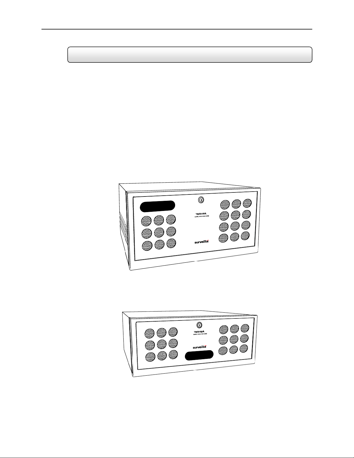
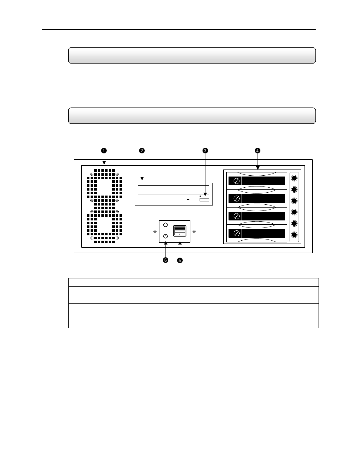
1.2 Front Panel Controls and LEDs
The front panel of the DVR unit contains the devices that will be commonly used for data
removal, retrieval, and backup replacement. The most common components and buttons are
shown below:
1.2.1 KV-DVR
1 Cooling Fan Air Intake 4 Hard Drive Array
2 CD-RW Drive 5 ON/OFF Power Switch
3 CD-RW Open Tray Button 6 Hard Drive Activity and Power LED
Display
7
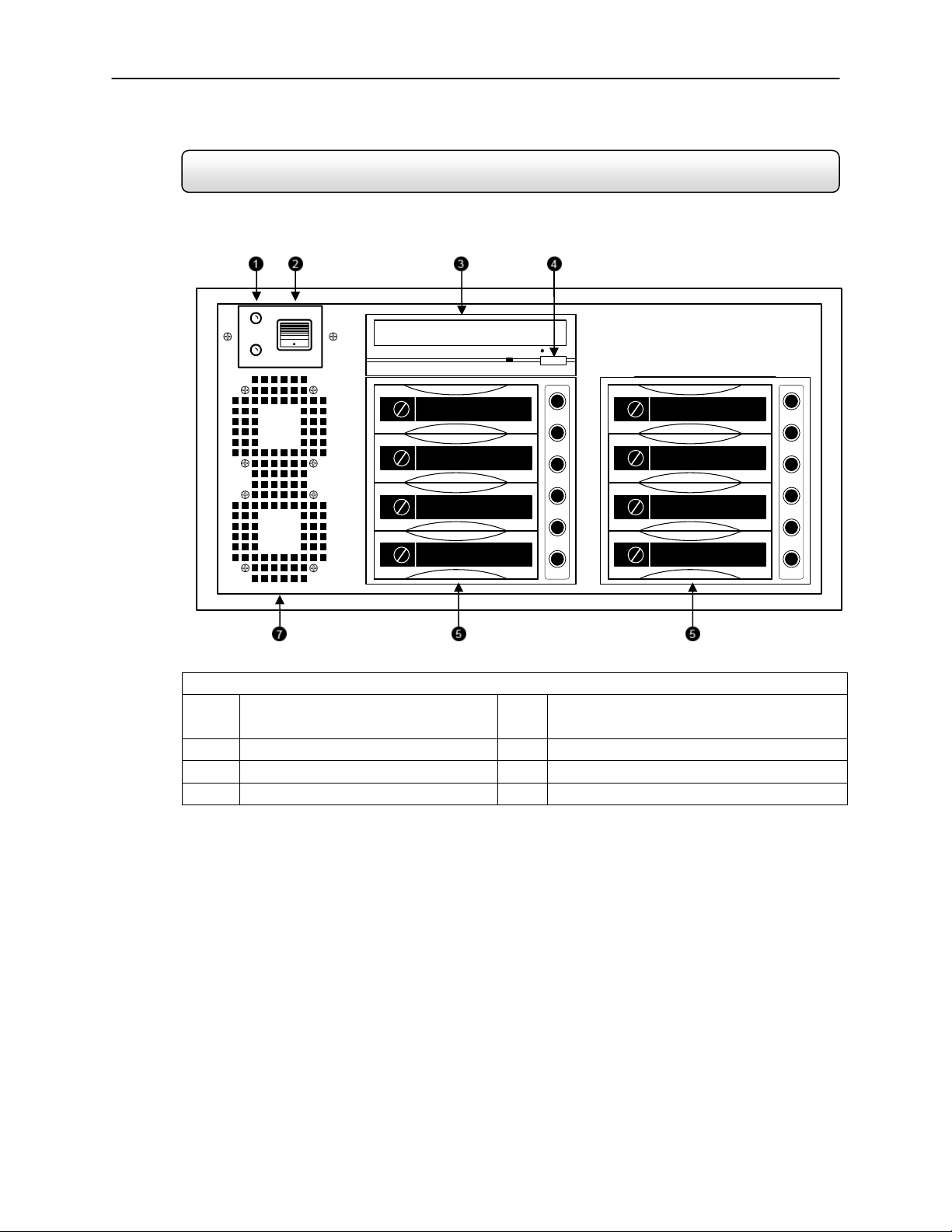
1.2.2 KV-EVR
1 Hard Drive Activity and Power
LED Display
4 CD-RW Open Tray Button
2 ON/OFF Power Switch 5 Hard Drive Array
3 CD-RW Drive 6 Cooling Fan Air Intake
8
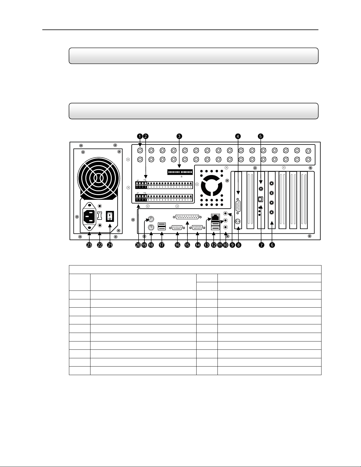
1.3 Rear Panel Connectors
The rear panel of the DVR unit contains virtually all of the connectors you will be using. Below
is a diagram that outlines the location and description of each connector:
1.3.1 KV-DVR
Figure 1.3
12 USB Ports 1 BNC Connector for Camera Input
and Looping Outputs
13 RJ-45 Network Jack
2 Sensor Inputs 14 DB-9 Serial Input 1
3 Looping outputs 15 LPT Parallel Printer Port
4 DB-15 SVGA Monitor Output 16 DB-9 Serial Input 2
5 RCA Video OUT 17 USB Ports
6 Audio Inputs 18 PS/2 Keyboard Input
7 RS-422 Interface 19 PS/2 Mouse Input
8 S-Video Output 20 Control Alarm Outputs
9 Audio Line In 21 Secondary Power switch
10 Audio Microphone In 22 110V / 220V Switch
11 Audio Speaker Out 23 IEEE AC Power Adapter
ON
OFF
1 C AM ER A 75 T ER M 16
1 2 3 4 5 6 7 8 9 10 11 12 13 14 15 16
CON
COM2
COM1
CH 1 in CH 2 in CH 3 in CH 4 in CH 5 in CH 6 in CH 7 in CH 8 in CH 9 in CH 10 in CH 11 in CH 12 in CH 13 in CH 14 in CH 15 in CH 16 in
CH 1 Out CH 2 Out CH 3 Out CH 4 Out CH 5 Out CH 6 Out CH 7 Out CH 8 Out CH 9 Out CH 10 Out CH 11 Out CH 12 Out CH 13 Out CH 14 Out CH 15 Out CH 16 Out
1 2 3 4 5 6 7 8 9 10 11 12 13 14 15 16
SEN
9
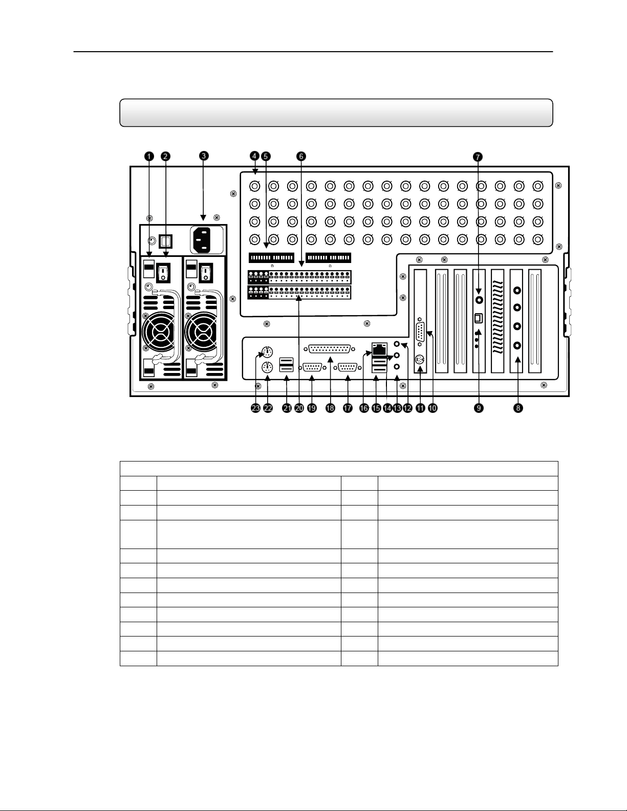
1.3.2 KV-EVR
Figure 1.3
1 110V / 220V Switch 13 Audio Microphone In
2 Secondary Power switch 14 Audio Speaker Out
3 IEEE AC Power Adapter 15 USB Ports
4 BNC Connector for Camera Input
and Looping Outputs
16 RJ-45 Network Jack
5 Looping outputs 17 DB-9 Serial Input 1
6 Sensor Inputs 18 LPT Parallel Printer Port
7 RCA Video OUT 19 DB-9 Serial Input 2
8 Audio Inputs 20 Control Alarm Outputs
9 RS-422 Interface 21 USB Ports
10 DB-15 SVGA Monitor Output 22 PS/2 Keyboard Input
11 S-Video Output 23 PS/2 Mouse Input
12 Audio Line In
ON
OFF
ON
OFF
CH 1 in CH 2 in CH 3 in CH 4 in CH 5 in CH 6 in CH 7 in CH 8 in CH 9 in CH 10 in CH 11 in CH 12 in CH 13 in CH 14 in CH 15 in CH 16 in
CH 17 in CH 18 in CH 19 in CH 20 in CH 21 in CH 22 in CH 23 in CH 24 in CH 25 in CH 26 in CH 27 in CH 28 in CH 29 in CH 30 in CH 31 in CH 32 in
CH 1 Out CH 2 Out CH 3 Out CH 4 Out CH 5 Out CH 6 Out CH 7 Out CH 8 Out CH 9 Out CH 10 Out CH 11 Out CH 12 Out CH 13 Out CH 14 Out CH 15 Out CH 16 Out
CH 17 Out CH 18 Out CH 19 Out CH 20 Out CH 21 Out CH 22 Out CH 23 Out CH 24 Out CH 25 Out CH 26 Out CH 27 Out CH 28 Out CH 29 Out CH 30 Out CH 31 Out CH 32 Out
17
C
AME
RA
75 TERM 32
1C
AME
RA
75 TERM 16
SEN
CO N
C
OM
2
C
OM
1

10

11
CHAPTER
Getting Started
This chapter includes the following information:
Included Components
Setting up your DVR Hardware
Optional Components
12
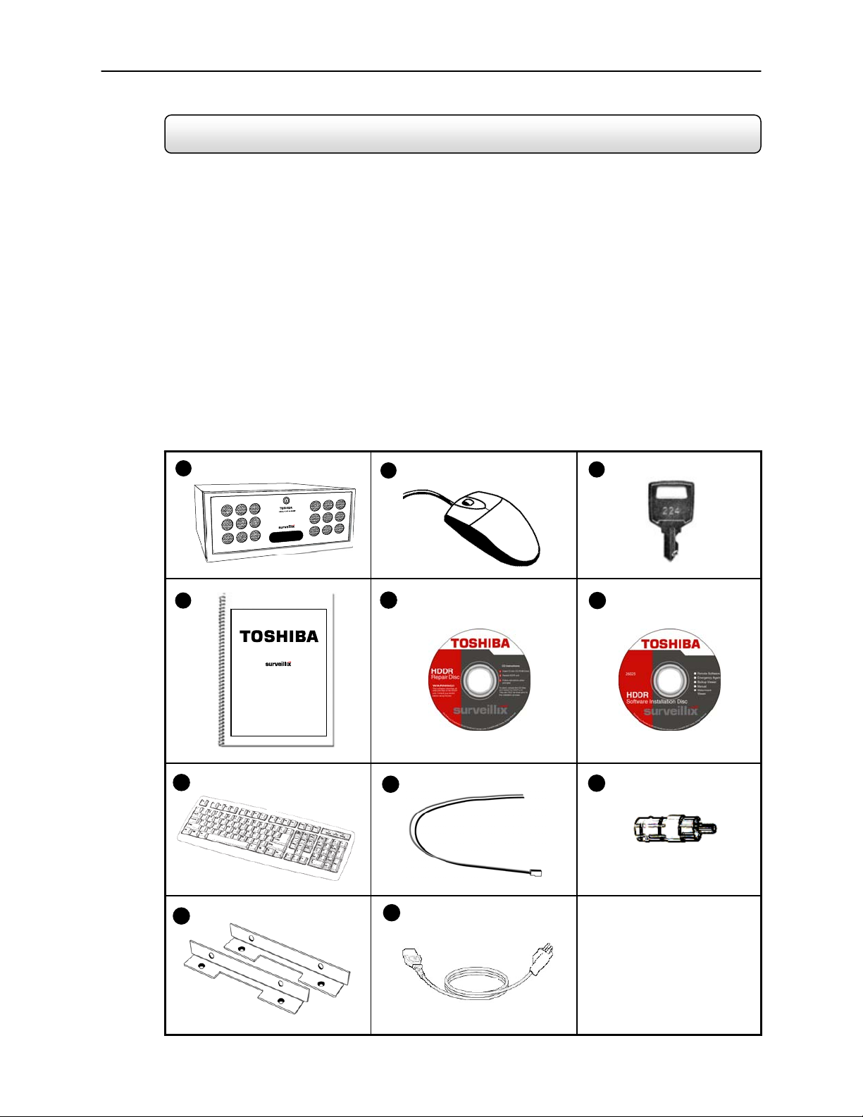
2.1 Identifying included components
Surveillix™ DVRs come with a mouse, keyboard and selected software and cables. Identify the following components
to make sure everything has been properly included with your new DVR unit. If any of the following items are missing,
contact your dealer to arrange a replacement.
Included Component List:
1. DVR Unit
2. Mouse
3. DVR Key
4. Manual
5. Repair CD
6. Software Installation CD
7. Keyboard
8. PTZ Adapter
9. RCA to BNC Adapter
10. Rackmount Attachments with Screws
11. Power Cable
1
2
3
4
5
6
7
8
9
10
11
13
2.2 Keyboard Setup
To attach the keyboard to the DVR unit, plug the end of the Keybo ard into the keyboard PS/2 Port located on the ba ck
of the machine. The keyboard PS/2 Port can be identified by the purple color. Refer to the Rear Panel Connectors
diagram for more information.
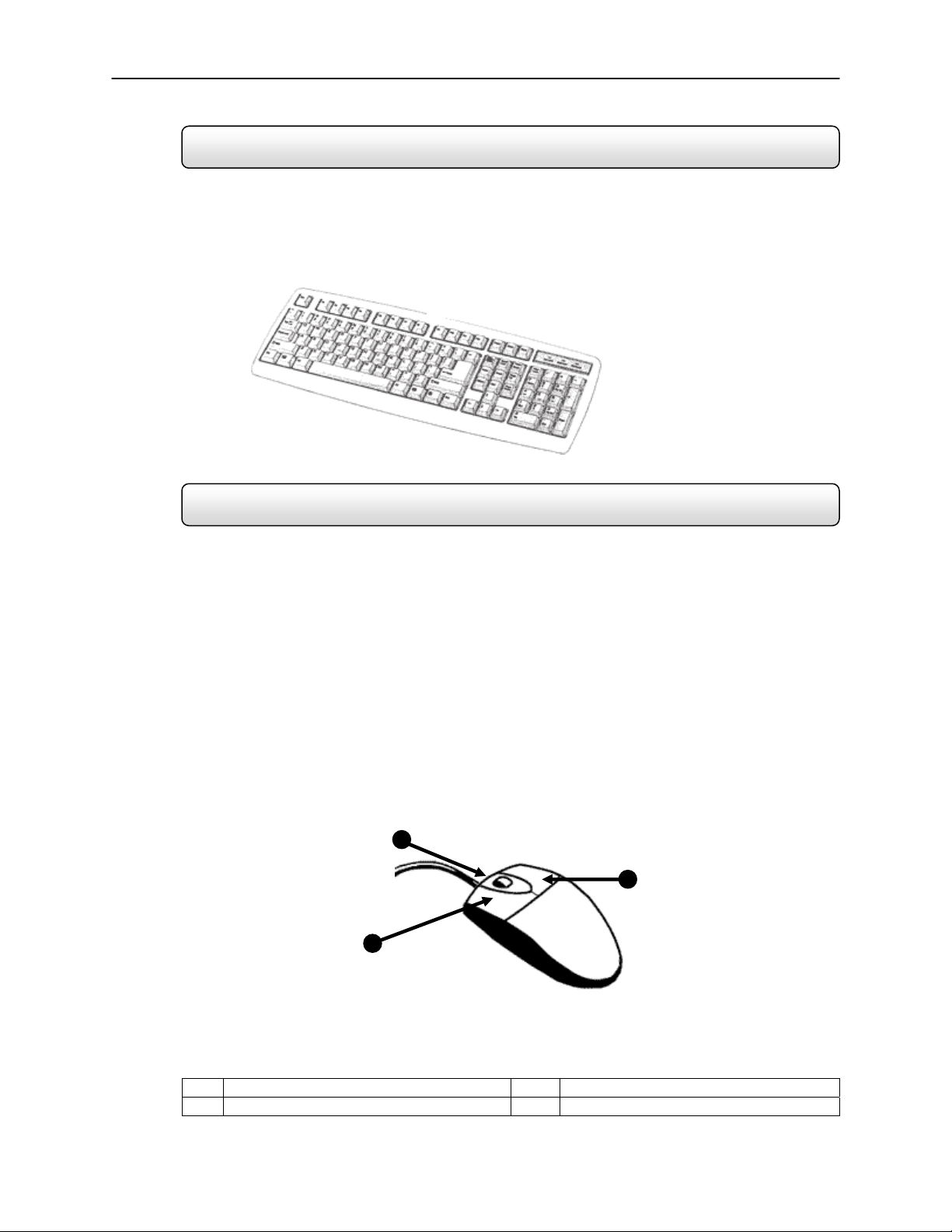
2.3 Mouse Setup
To attach the mouse to the DVR unit, plug the end of the mouse into the mouse PS/2 Port located on the back of the
machine. The mouse PS/2 Port can be identified by the green color. Refer to the Rear Panel Connectors diagram for
more information.
The mouse uses a cursor called a pointer. Pointers come in many different shapes but are most commonly shaped like
an arrow.
Your mouse has two buttons: a left button and a right button. Quickly pressing and releasing one of these buttons is
called clicking. Sometimes you will need to double-click – or click the same button twice quickly.
In this manual, click means to position your mouse point on an icon and to single click the left button. When a right click
is required, this is stated clearly. Double-click also refers to the left button.
The ratchet wheel in between the two buttons is added to provide easier scrolling capability. By simply moving the
wheel with your index finger, you can quickly move through multiple pages, line, or windows. The wheel may also
function as a third button allowing you to quickly click or double-click an icon or a selected item.
1 Left Button 3 Right Button
2 Scroll button / Third Button
Fi
g
ure 2.
3
Figure 2.3
1
2
3
14
2.4 Monitor Setup
Attach the Monitor to the Rear of the DVR unit using the VGA cable supplied by the Monitor Manufacturer. Refer to
your monitor manual for detailed information on how to setup and use it.
NOTE: The monitor you use must be capable of having a screen resolution of 1024 x 768 and display colors of at least 24 Bit
2.5 Power Setup
Attach the AC power cable to the rear of the DVR Unit. See Rear Panel Connectors for more information.
WARNING: To reduce the risk of electrical shock or damage to the equipment:
• Do not disable the power grounding plug. The grounding plug is an important safety feature.
• Plug the power cord into a grounded (earthed) electrical outlet that is easily accessible at all times.
• Disconnect the power from the computer by unplugging the power cord either from the electrical outlet or the
computer.
2.6 Connecting a Video Source to the DVR
There are different types of Video Sources that can be plugged into your DVR unit including DVD players, VHS players,
and CCTV Cameras. The back of the DVR unit contains up to 16 video inputs depending on the DVR model. The
connectors use the BNC standard. On the KV-PCDVR32 32 Channel DVR, all 32 of these ports are used as inputs.
Video Inputs – The Video inputs are RG-59 BNC connectors. Simply plug one end into your video source (DVD,
Camera, etc.) and plug the other end into the desired BNC input on the DVR unit.
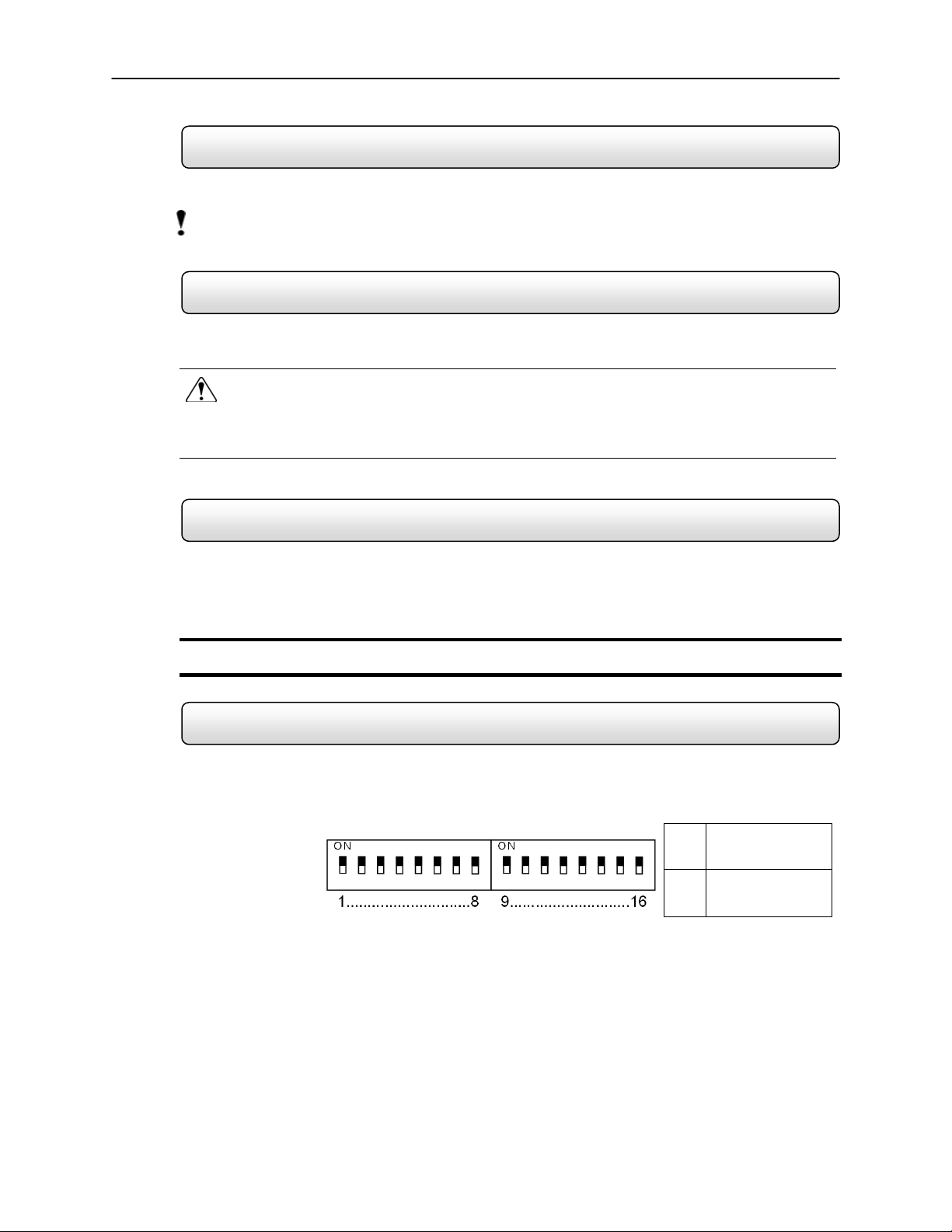
2.7 Looping Output Termination
When terminating the outputs becomes necessary, the DVR unit has built-in termination that allows you to select
individual outputs to be terminated. Generally it is not necessary to terminate the output when using it. It is dependant
on if the device to which you are connecting it, has internal 75 ohm termination. As a rule, if the image appears
distorted or virtually unviewable, it most likely needs to be terminated.
ON
Not connected to a
monitor (Normal)
Terminating
the Looping
Outputs
OFF
Connected to a
monitor
(Looped)
Always leave the dipswitch set to the ON position when the Looping Outputs are not used.
15
2.8 Connecting Sensors to the DVR
Each DVR unit may have up to 16 Sensor inputs. These inputs can be used with devices such as Infrared devices,
motion devices, glass breakage alarms, door and window trips, and many more. The Sensors can be set to Normally
Open or Normally Closed inside the software.
There are 4 Commons (-) and 16 inputs (+). There is no power supplied to the ports so an external power supply must
be used if power becomes necessary.
Sensor Input
• Normally Open or Normally Closed option is available inside the DVR Software.
• There is no power supplied to the ports. Use an external power supply if necessary.
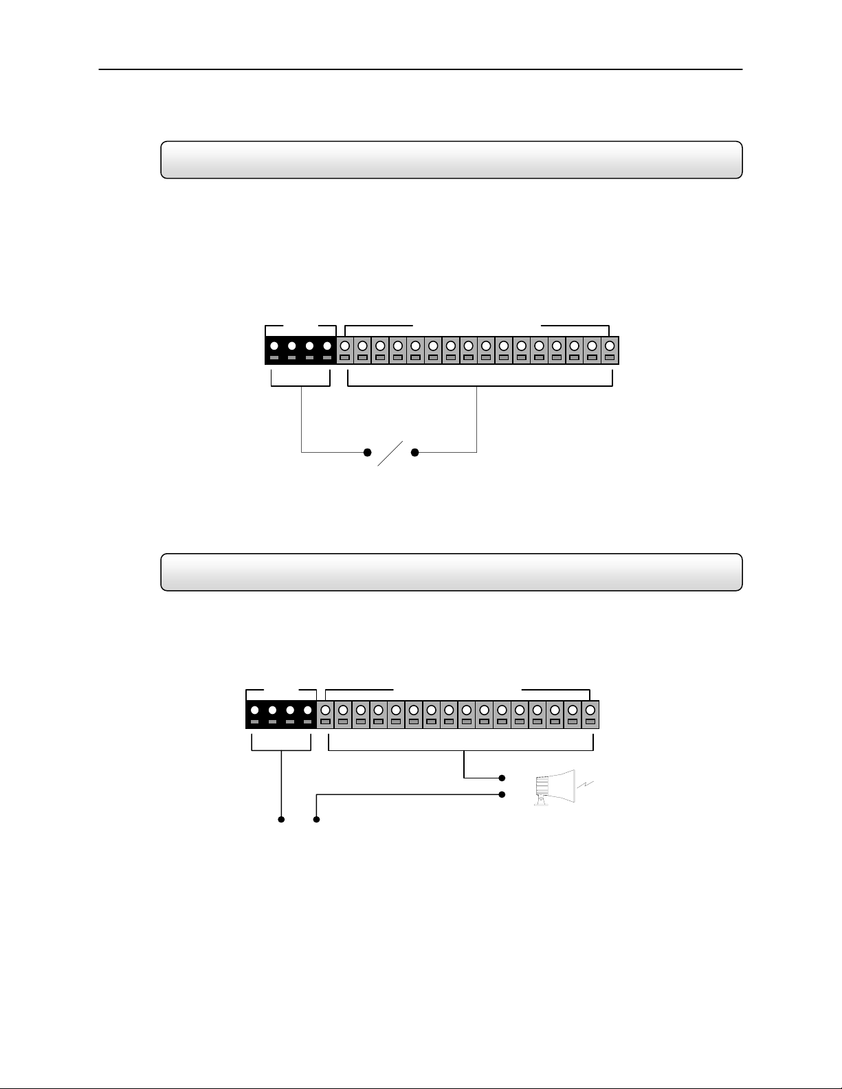
2.9 Connecting Control Outputs to the DVR
Each DVR unit may have up to 16 Control Outputs. These outputs can be used to trigger devices such as Sirens,
Phone Dialers, Lights, and any other relay activated device.
Control Output
• Use 12V, below 300mA. For controlling lights or other devices, use another external relay.
• Maximum voltage is 24V AC @ 1 amp
• Output uses a Form C Relay
COM
Sensor (1 ~ 16)
COM
Control Out (1 ~ 16)
(+)
(-)
External Power Supply ( DC 12V)
Siren, Alarm, Outside Relays
 Loading...