


CCD Color Camera
GiantDragon Color series
CSGV90CC3
CSGX36CC3
CSGS20CC2
CSGU15CC18
Instruction Manual
Thank you for purchasing our product.
Before using this CCD Color Camera, please read through this instruction manual carefully in order to use this product correctly and safely.
After reading, keep this instruction manual handy so that you can refer to, whenever you need it.
Contents
Safety Precautions
1.Overview·····························································································1
2.Features ·······························································································1
3.Configuration ······················································································2
4.Optional part························································································2
5.Explanation rear panel·········································································3
6.Connection ··························································································4
7.Functions·····························································································5
8.Timing chart ························································································8
9.Troubleshooting··················································································10
10.Specifications ···················································································11
11.Outline Drawing···············································································17
Printed on recycled paper
D4153660A

Safety Precautions
Before using this product, read these safety precautions carefully. Important information is shown in this Instruction Manual to protect users from bodily injuries and property damages, and to enable them to use the product safely and correctly.
Please be sure to thoroughly understand the meanings of the following signs and symbols before reading the main text that follow, and observe the instructions given herein.
[Definition of Safety Signs]
Safety Signs |
Description |
|
WARNING |
Indicates a potentially hazardous situation that may result in death or |
|
serious injury (*1) in the event of improper handling. |
||
|
Indicates a potentially hazardous situation that may result in light to CAUTION moderate injuries (*2) or only in property damage (*3)in the event of
improper handling.
Notes *1: “Serious injury” refers to cases of loss of eyesight, wounds, burns (high or low temperature), electric shock, broken bones, poisoning, etc., which leave after-effects or which require hospitalization or a long period of outpatient treatment of cure.
*2: "Light to moderate injuries" refers to injuries, burns, electric shock etc. that do not require hospitalization or long-term treatment.
*3: "Property damage" refers to cases of extensive damage involving damage to buildings, equipment, farm animals, pet animals and other belongings.
[Explanation of Safety Symbols]
Safety Symbols |
Description |
|
|
PROHIBITED |
This sign indicates PROHIBITION (Do not). |
The content of prohibition is shown by a picture or words beside the |
|
|
symbol. |
|
This sign indicates MANDATORY ACTION (You are required to |
MANDATORY |
do). |
|
The content of action is shown by a picture or words beside the |
|
symbol. |
D4153660A

[General Handing]
 WARNING
! Stop operation immediately when any abnormality or defect occurs.
If abnormal conditions are present, such as smoke, a burning smell, ingress of water or foreign matter, or if the equipment is dropped or malfunctions, fire or electric shock may result.
Be always sure to disconnect the power cable from the wall socket at once and contact your Unplug dealer.
!Do not use the equipment in locations subject to water splashes.
Otherwise, fire or electric shock may result.
Do not get wet
!Do not disassemble, repair, or modify the equipment.
Otherwise, fire or electric shock may result.
For internal repair, inspection, or cleaning, contact your sales representative.
Never pull apart
!Do not place anything on the equipment.
If metallic objects, liquid, or other foreign matter enters the equipment, fire or electric shock may result.
Avoid
!Do not install the equipment in an unstable or inclined location or locations subject to vibration or impact.
Otherwise, the equipment may topple over and cause personal injury.
Avoid
!During an electrical storm, do not touch the power cable and the connection cable.
Otherwise, an electric shock may result.
Do not touch
!Use the specified voltage.
Use of an unspecified voltage may result in fire or electric shock.
Instruction
!Do not be handled roughly, damaged, fabricated, bent forcefully, pulled, twisted, bundled,
placed under heavy objects or heated the power cable and the connection cable.
Otherwise, fire or electric shock may result.
Avoid
D4153660A

[General Handing]
|
|
CAUTION |
|
! Observe the following when installing the equipment: |
|
|
· |
Do not cover the equipment with a cloth, etc. |
|
· |
Do not place the equipment in a narrow location where heat is likely to accumulate. |
Instruction |
Otherwise, heat will accumulate inside the equipment, possibly resulting in a fire. |
|
|
|
|
|
|
|
!Do not place the equipment in locations subject to high moisture, oil fumes, steam, or dust.
Otherwise, fire or electric shock may result.
Avoid
!Do not install the equipment in locations exposed to direct sunlight or humidity.
Otherwise, the internal temperature of the equipment will rise, which may cause a fire.
Avoid
!Use only specified the power cable and the connection cables.
Otherwise, fire or electric shock may result.
Instruction
!When performing connection, turn off power.
When connecting the power cable and the connection cable, turn off the equipment power. Otherwise, fire or electric shock may result.
Instruction
!Do not expose its camera head to any intensive light (such as direct sunlight).
Otherwise, its inner image pickup device might get damaged.
Avoid
!Avoid short-circuiting signal output.
Otherwise, a malfunction may occur.
Avoid
!Avoid giving a strong shock against the camera body.
It might cause a breakdown or damage. If your camera is used in a system where its camera connector is subjected to strong repetitive shocks, its camera connector is possible to break down. If you intend to use your camera in such a situation, if possible, bundle and fix a camera
Avoid |
cable in the place near the camera, and do not transmit a shock to the camera connector. |
|
|
!Contact your sales representative to request periodic inspection and cleaning (every approx five years).
Accumulation of dust inside the equipment may result in fire or electric shock.
Instruction |
For inspection and cleaning costs, contact your sales representative. |
|
|
|
|
D4153660A

CASES FOR INDEMNITY (LIMITED WARRANTY)
We shall be exempted from taking responsibility and held harmless for damage or losses incurred by the user in the following cases.
!In the case damage or losses are caused by fire, earthquake, or other acts of God, acts by a third party, deliberate or accidental misuse by the user, or use under extreme operating conditions.
!In the case of indirect, additional, consequential damages (loss of business interests, suspension of business activities) are incurred as result of malfunction or non-function of the equipment, we shall be exempted from responsibility for such damages.
!In the case damage or losses are caused by failure to observe the information contained in the instructions in this instruction manual and specifications.
!In the case damage or losses are caused by use contrary to the instructions in this instruction manual and specifications.
!In the case damage or losses are caused by malfunction or other problems resulting from use of equipment (connected equipments including Gigabit Ethernet Interface board, the lens, etc.) or software that is not specified.
!In the case damage or losses are caused by repair or modification conducted by the customer or any unauthorized third party (such as an unauthorized service representative).
!Expenses we bear on this product shall be limited to the individual price of the product.
RESTRICTION FOR USE
!Should the equipment be used in the following conditions or environments, give consideration to safety measures and inform us of such usage:
1.Use of the equipment in the conditions or environment contrary to those specified, or use outdoors.
2.Use of the equipment in applications expected to cause potential hazard to people or property, which require special safety measures to be adopted.
!This product can be used under diverse operating conditions. Determination of applicability of equipment or devices concerned shall be determined after analysis or testing as necessary by the designer of such equipment or devices, or personnel related to the specifications. Such designer or personnel shall assure the performance and safety of the equipment or devices.
!This product is not designed or manufactured to be used for control of equipment directly concerned with human life (*1) or equipment relating to maintenance of public services/functions involving factors of safety (*2). Therefore, the product shall not be used for such applications.
(*1): Equipment directly concerned with human life refers to.
·Medical equipment such as life-support systems, equipment for operating theaters.
·Exhaust control equipment for exhaust gases such as toxic fumes or smoke.
·Equipment mandatory to be installed by various laws and regulations such as the Fire Act or Building Standard Law
·Equipment related to the above
(*2) :Equipment relating to maintenance of public services/functions involving factors of safety refers to.
·Traffic control systems for air transportation, railways, roads, or marine transportation
·Equipment for nuclear power generation
·Equipment related to the above
D4153660A

Notes on using this product
!Handle carefully
Do not drop the equipment or allow it to be subject to strong impact or vibration, as such action may cause malfunctions. Further, do not damage the connection cable, since this may cause wire breakage.
!Environmental operating conditions
Do not use the product in locations where the ambient temperature or humidity exceeds the specifications. Otherwise, image quality may be degraded or internal components may be adversely affected. In particular, do not use the product in areas exposed to direct sunlight. Moreover, during shooting under high temperatures, vertical stripes or white spots (noise) may be produced, depending on the subject or camera conditions (such as increased gain). However, such phenomena are not malfunctions.
!Check a combination with the lens
Depending on the lens and lighting you use, an image is reflected as a ghost in the imaging area. However, this is not because of a fault of the camera.
In addition, depending on the lens you use, the performance of the camera may not be brought out fully due to deterioration in resolution and brightness in the peripheral area, aberration and others.
Be sure to check a combination with the camera by using the lens and lightning you actually use. When installing a lens in the camera, make sure carefully that it is not tilted.
In addition, use a mounting screw free from defects and dirt. Otherwise, the camera may be unable to be removed.
!Do not shoot under intense light
Avoid intense light such as spot lights on part of the screen because it may cause blooming or smears. If intense light falls on the screen, vertical stripes may appear on the screen, but this is not a malfunction.
!Occurrence of moiré
If you shoot thin stripe patterns, moiré patterns (interference fringes) may appear. This is not a malfunction.
!Occurrence of noise on the screen
If an intense magnetic or electromagnetic field is generated near the camera or connection cable, noise may be generated on the screen. If this occurs, move the camera or the cable.
!Handling of the protective cap
If the camera is not in use, attach the lens cap to the camera to protect the image pickup surface.
!If the equipment is not to be used for a long duration
Turn off power to the camera for safety.
!Maintenance
Turn off power to the equipment and wipe it with a dry cloth.
If it becomes severely contaminated, gently wipe the affected areas with a soft cloth dampened with diluted neutral detergent. Never use alcohol, benzene, thinner, or other chemicals because such chemicals may damage or discolor the paint and indications.
If the image pickup surface becomes dusty, contaminated, or scratched, consult your sales representative.
!Disposal
When disposing of the camera, it may be necessary to disassemble it into separate parts, in accordance with the laws and regulations of your country and/or municipality concerning environmental contamination.
D4153660A

Following information is only for EU-member states:
The use of the symbol indicates that this product may not be treated as household waste. By ensuring this product is disposed of correctly, you will help prevent potential negative consequences for the environment and human health, which could otherwise be caused by inappropriate waste handling of this product. For more detailed information about the take-back and recycling of this product, please contact your supplier where you purchased the product.
This equipment has been tested and found to comply with the limits for a class A digital device, pursuant to Part 15 of the FCC Rules.
These limits are designed to provide reasonable protection against harmful interference when the equipment is operated in a commercial environment.
This equipment generates, uses, and can radiate radio frequency energy and, if not installed and used in accordance with the instruction manual, may cause harmful interference to radio communication. Operation of this equipment in a residential area is likely to cause harmful interference in which case the user will be require to correct the interference at his own expense.
D4153660A
 10
10
信息产品污染控制标识要求(SJ/T11364-2006)
/
The Mark and Information are applicable for People's Republic of China only.
|
|
|
|
|
|
|
|
|
|
|
|
|
|
Pb |
Hg |
Cd |
|
|
|
|
|
Cr(VI) |
PBB |
(PBDE |
|||
|
|
|
|
|
|
|
|
× |
○ |
○ |
○ |
○ |
○ |
|
|
|
|
|
|
|
○ (SJ/T11363-2006)
× (SJ/T11363-2006)
This information is applicable for People's Republic of China only.
( )
Information on recycling of wrapping composition
|
|
|
Box |
|
|
Internal buffer materials |
||
|

 CB
CB
Corrugated cardboard
OTHERS
D4153660A
1. Overview
This GiantDragon Color series is an integrated-(one-body)-type color camera that adopts all pixel data readout inter line CCD. There are 4 models according to the sensor type. These are CSGV90CC3 (VGA), CSGX36CC3 (XGA), CSGS20CC2 (SXGA), and CSGU15CC18 (UXGA). For video output, the Gigabit Ethernet®* interface standard “IEEE802.3ab” is adopted for high transfer rate, and it is easy to integrate into industrial equipment.
* Ethernet® is a registered trademark of XEROX Corporation.
2. Features
! High frame rate and high resolution
Supported high frame rate CSGV90CC3 (90fps/VGA), CSGX36CC3 (36fps/XGA), CSGS20CC2 (20fps/SXGA), and CSGU15CC18 (15fps/UXGA).
! All pixel readout
All pixel signals (in the effective area) are output in one frame processing.
! Full frame shutter
Since all pixels are output even by shutter operation, high resolution can be achieved, without deteriorating the vertical resolution.
! Square grids
The CCD pixels arrayed in square grids facilitates computation for image processing.
! Color processing
Since color processing is built in, there are also RGB (24bit), YUV 4:2:2 (16bit), YUV 4:1:1 (12bit) output modes besides Raw output mode (8/10bit).
! Gigabit Ethernet interface
Performs video output and camera control via the Gigabit Ethernet standard IEEE802.3ab interface. Data transfer is at 1Gbps that can output uncompressed video data of high frame rate.
! GigEVision Ver 1.0 conformity
This product is based on GigEVision Camera Interface Standard for Machine Vision Ver 1.0 that is industrial camera standard. Therefore, control of this camera is easy.
! GenICam Ver 1.0 conformity
This product is based on GenICam Generic Interface for Cameras Ver 1.0 that is industrial camera standard. Therefore, control of this camera is easy.
1 |
D4153660A |
! High-speed draft readout mode
By thinning out vertical lines, it can be read all effective area at high-speed frame rate.
! Random trigger shutter
The random trigger shutter function provides images in any timing by input of an external trigger signal. Trigger control from PC is possible.
! Scalable
Selectable video output area. It can be higher frame rate by reducing vertical output area. And can be reduce occupied data rate of Gigabit Ethernet by reducing horizontal output area.
! Compact and lightweight
This camera is compact and lightweight, and it is easy to integrate into industrial equipment.
! EU RoHS & Chinese ROHS compliant
3. Configuration
(1)Camera body ············································ 1
(2)Accessories
- Instruction Manual (Japanese) |
············· 1 |
- Instruction Manual (English) |
··············· 1 |
* No application software is attached to this camera.
4. Optional part
(1)Camera mounting kit·································· Model name: CPT8420
(2)Camera cable ············································· Model name: CPRC3910-**
(3)Camera adapter·········································· Model name: CA130C
* Contact your dealer / distributor for details of option units.
2 |
D4153660A |
5. Explanation rear panel
(1) Ethernet |
|
|
Gigabit Ethernet Interface connector |
|
|||
- Connector model |
|
|
P65-P01-19V8 (Supplied by SpeedTech Corp.) |
||||
- Pin assignment |
|
|
|
|
|
||
|
|
|
|
|
|
|
|
|
Pin No. |
|
I/O |
Function |
|
(1) |
(2) |
|
1 |
|
I/O |
BI_DA+ |
|
|
|
|
|
|
|
|
|
|
|
|
2 |
|
I/O |
BI_DA- |
|
|
|
|
|
|
|
|
|
|
|
|
3 |
|
I/O |
BI_DB+ |
|
|
|
|
|
|
|
|
|
|
|
|
4 |
|
I/O |
BI_DC+ |
|
|
|
|
|
|
|
|
|
|
|
|
5 |
|
I/O |
BI_DC- |
|
|
|
|
|
|
|
|
|
LED1 |
|
|
6 |
|
I/O |
BI_DB- |
|
|
|
|
|
|
|
|
|||
|
|
|
|
|
|
|
|
|
7 |
|
I/O |
BI_DD+ |
|
|
|
|
|
|
|
|
|
|
|
|
8 |
|
I/O |
BI_DD- |
|
Rear View |
LED2 |
|
|
|
|
|
|
||
|
|
|
|
|
|
||
- Indication LED1: GREEN (ACT LED) |
LED1 indicates the state of ACT. |
|
|||||
|
During transfer: |
|
|
Lighting |
|
||
- Indication LED2: YELLOW (LINK LED) |
LED2 indicates the state of LINK. |
|
|||||
|
During Link: |
|
|
Lighting |
|
||
* LINK LED indicates establishment of Link of 1000BASE. Therefore, in the case of 100BASE/10BASE, LINK LED does not light.
(2)DC_IN / TRIGGER
-Connector (Camera side)
-Plug (Cable side)
-Pin assignment
Pin No. |
Signal Name |
|
[Standard specification] |
||
|
||
1 |
BUSY_OUT |
|
|
|
|
2 |
GND |
|
|
|
|
3 |
GND |
|
|
|
|
4 |
TRIG_IN |
|
|
|
|
5 |
EXPOSE_OUT |
|
|
|
|
6 |
+12V |
|
|
|
HR10A-7R-6PB(73)
(Supplied by HIROSE ELECTRIC CO., LTD.) HR10A-7P-6S(73)
(Supplied by HIROSE ELECTRIC CO., LTD.) or equivalents
* This camera cable is not an accessory of this product.
1 6
2 5
34
*Above figure is connector view from insert side.
3 |
D4153660A |
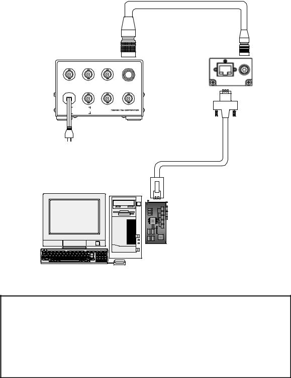
6. Connection
Connect this camera as shown in the figure below.
(The figure below shows an example of connection. For details, contact our sales representative.)
Option
CameraAdapter
CA130C
TRIGGER |
HD |
VD |
CAMERA |
AC100VIN |
WEN |
VIDEO OUT CLOCK OUT |
|
CA130C |
TYPE2232A5900 |
|
|
SERIALNo. |
|
AC100V0.15A |
|
Option
CameraCable
CPRC3910-**
CCDColorCamera
GiantDragon
(Rear-side)
AC100V
50/60Hz |
|
|
|
LAN Cable |
|
PC |
Twist-pair |
|
Category5eorover |
||
|
GigabitEthernet
interfaceboard
Notes on Connection:
-If your camera is used in a system where its connectors are subjected to strong repetitive shocks, its connectors are possible to break down. If you use your camera in such a situation, use an LAN cable with a lock screw, and secure the camera cable as close as possible to the camera body for avoid physical shock to the camera connector.
-Since the Optional parts and Gigabit Ethernet interface board, cable not attached to this product, please prepare it if necessary.
4 |
D4153660A |

7. Functions
Control and setting of functions can be done by the camera control based on the Gigabit Ethernet digital camera protocol (GigEVision Ver.1.00).
(1) Image output
A format of the output image and frame rate which this GiantDragon Color series supports is as follows.
Model |
CSGV90CC3 |
CSGX36CC3 |
CSGS20CC2 |
CSGU15CC18 |
|
GVSP_PIX_YUV411_PACKED: YUV4:1:1 12bit |
|||
|
GVSP_PIX_YUV422_PACKED: YUV4:2:2 16bit |
|||
|
GVSP_PIX_RGB8_PACKED: RGB 24bit |
|||
Image output format |
GVSP_PIX_BAYRG8 |
GVSP_PIX_BAYGB8 |
GVSP_PIX_BAYRG8 |
|
|
Raw(BayRG8)8bit |
Raw(BayGB8) 8bit |
Raw(BayRG8)8bit |
|
|
|
|
|
|
|
GVSP_PIX_BAYRG10 |
GVSP_PIX_BAYGB10 |
GVSP_PIX_BAYRG10 |
|
|
Raw(BayRG10)10bit |
Raw(BayGB8) 10bit |
Raw(BayRG10)10bit |
|
|
|
|
|
|
Frame rate |
Maximum |
Maximum |
Maximum |
Maximum |
(at the all pixel readout) |
90fps |
36fps |
20fps |
15fps |
|
|
|
|
|
Notes on Frame Drops of Image:
-Depends on your PC or Gigabit Ethernet interface board configurations, images may not be captured normally (e.g. frame drops may occur). In this case, change to frame rate setting lower.
(2)Setup-level setting
You can set the Setup-level in 192 steps in the range between 6.3 and 25%.
(3) Gain setting
There is AGC (Auto Gain Control) other than manual setting, too. Setting range and effective range are 0 to +6dB.
(4) White balance
There are two types of white balancing mode, MWB (Manual White Balance) and OPWB (One Push White Balance). You can set white balancing mode, according to the subject and purpose.
(5) Gamma correction
You can set gamma correction ON/OFF.
*The user cannot adjust the correction amount.
(6)Masking correction
The hue of images is masking corrected so that it will be natural (ON fixed). * The user cannot adjust the correction amount.
5 |
D4153660A |

(7) High-speed draft readout mode
By thinning out vertical lines, it can be read all effective area at high-speed frame rate. * As for CSGV90CC3 (VGA), this mode supports a fault.
|
CSGV90CC3 |
CSGX36CC3 |
CSGS20CC2 |
CSGU15CC18 |
Draft mode |
|
1/3 |
1/2 |
1/4 |
Readout vertical line number |
|
254 |
480 |
300 |
Maximum frame rate |
|
86 fps |
34fps |
46fps |
(8) Image resending control
As the resending control of the image, this camera resends the packet which suffered a loss.
(9) Electronic shutter mode switching
You can switch the shutter modes by adjusting the setting value of the command status register of the camera via the Gigabit Ethernet. The setting method has three kinds of the following.
- AE (Auto Exposure)
The brightness is adjusted automatically by the average photometry of the entire screen.
Effective range |
1/20000s to Setting value of the frame rate |
Effective area |
Full screen |
Exposure level |
-1EV to +1EV (1/3EV step) |
By combining this mode and AGC (ALC mode), it can follow so much to brightness change of subject. - Normal shutter
Performs exposure control via the internal synchronization signal.
PRESET setting: |
1/100s, 1/250s, 1/500s, 1/1000s, 1/2000s , 1/4000, 1/10000, |
|
and 1/20000s |
Absolute value setting |
Any value is set up in 32-bit floating point form within the range |
|
of 1/20000s to 2s |
- Random trigger shutter
Random trigger shutter can capture images at any timing using the external trigger signal and soft trigger input. It is effective for image input of moving objects and obtaining images of the same timing using multiple cameras. But there is an exposure delay time.
The random trigger shutter of this camera can be operated in two types of mode. How to determine the exposure time differs depending on the mode.
Fixed mode: The exposure time depends on the normal shutter speed setting. Pulse width mode : The exposure time depends on the pulse width.
Notes on fixed mode of Random trigger shutter:
- It is outside a guarantee when having set it as this mode, and a normal shutter is turned off. Please be sure to turn on a normal shutter.
Notes on long exposure:
- When you set the exposure time longer than approximately 1 second, white spots and the unevenness in highlight portion might occasionally be observed on screen. This phenomenon is due to the characteristics of the CCD image-pickup device, and do not reflect performance error in the pickup device or CCD Camera itself.
6 |
D4153660A |
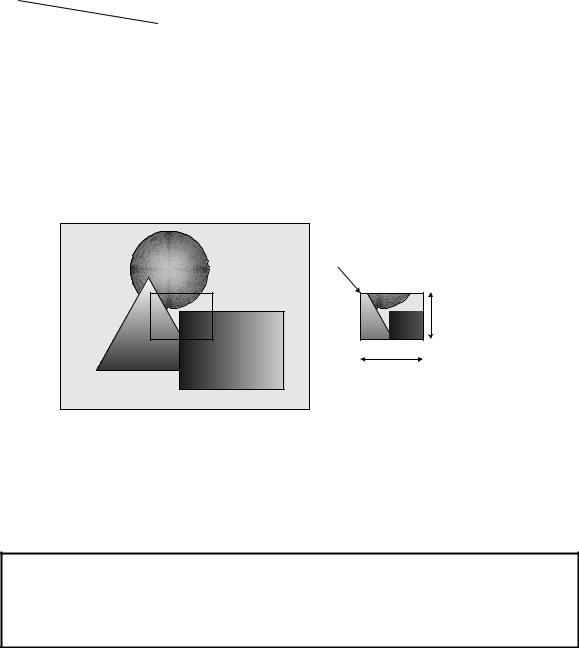
(10) Scalable mode
This camera has the scalable mode that can read out defined area of the screen. Only continuous rectangle units can be selected, concave or convex shape cannot be selected.
- Window size: |
{A x m(H)} x {B x n(V)} |
*A and B are minimum unit size.
*m, n=integer
*The image of maximum unit size or less can be selected.
*Only one window can be selected.
|
CSGV90CC3 |
CSGX36CC3 |
CSGS20CC2 |
CSGU15CC18 |
|
|
|
|
|
|
|
Minimum unit size |
160 x 120 |
256 x 192 |
160 x120 |
200 x 150 |
|
(H) x (V) |
|||||
|
|
|
|
||
|
|
|
|
|
|
Maximum unit size |
640 x 480 |
1024 x 768 |
1280 x 960 |
1600 x 1200 |
|
(H) x (V) |
|||||
|
|
|
|
||
|
|
|
|
|
|
- Start address: |
{32 x i(H)} x {24 x j(V)} |
|
|
||
*i, j=integer
*The image of maximum unit size or less can be selected.
Y) = (32 x i, 24 x j) |
|
(X,X , Y )=( 32 * i , 24 * j ) |
|
|
n x* B |
|
* |
|
A x m |
In the scalable mode, this camera reads out only the necessary portions at the standard speed while it scans through other unnecessary portions at high speed, so the trigger interval can be shorter if the vertical cutout width is small. However, the trigger interval cannot be short in the horizontal direction even if the cutout width is small due to the operation mechanism of the CCD sensor.
Notes on scalable mode:
-White lines may occur in the upper portions of the screen when strong light exists in a wide area during the scalable mode. This is not a malfunction. If white lines occur, adjust the amount of incident light using the lens.
7 |
D4153660A |
 Loading...