


AIR CONDITIONER (SPLIT TYPE)
Installation manual
Outdoor Unit |
For OUTDOOR USE only |
|
Model name: |
Not accessible to the general public |
|
Vente interdite au grand public |
||
RAV-SP240AT2-UL |
Kein öffentlicher Zugang |
|
Non accessibile a clienti generici |
||
|
||
|
No destinado al público en general |
|
|
Não acessível ao público em geral |
|
|
Niet geschikt voor huishoudelijk gebruik |
|
|
Μη προσβάσιμο από το γενικό κοινό |
Installation manual |
|
English |
Air conditioner (Split type) |
1 |
|
|
|
|
Manuel d'installation |
|
|
|
Français |
|
Climatiseur (Type split) |
23 |
|
|
|
|
Outdoor Unit |
Installation Manual |
Please read this Installation Manual carefully before installing the Air Conditioner.
•This Manual describes the installation method of the outdoor unit.
•For installation of the indoor unit, refer to the Installation Manual attached to the indoor unit.
ADOPTION OF NEW REFRIGERANT
This Air Conditioner uses R410A an environmentally friendly refrigerant.
Contents
1 DIMENSION . . . . . . . . . . . . . . . . . . . . . . . . . . . . . . . . . . . . . . . . . . . . . . . . . . . . . . . . . . 2 2 ACCESSORY PARTS. . . . . . . . . . . . . . . . . . . . . . . . . . . . . . . . . . . . . . . . . . . . . . . . . . . 3 3 SYSTEM REQUIREMENTS . . . . . . . . . . . . . . . . . . . . . . . . . . . . . . . . . . . . . . . . . . . . . . 4 4 PRECAUTIONS FOR SAFETY. . . . . . . . . . . . . . . . . . . . . . . . . . . . . . . . . . . . . . . . . . . . 5 5 INSTALLATION OF NEW REFRIGERANT AIR CONDITIONER. . . . . . . . . . . . . . . . . . 7 6 REFRIGERANT PIPING . . . . . . . . . . . . . . . . . . . . . . . . . . . . . . . . . . . . . . . . . . . . . . . . 12 7 ELECTRICAL CONNECTIONS . . . . . . . . . . . . . . . . . . . . . . . . . . . . . . . . . . . . . . . . . . 14 8 EVACUATE AND DEHYDRATE THE SYSTEM. . . . . . . . . . . . . . . . . . . . . . . . . . . . . . 17 9 FINISHING. . . . . . . . . . . . . . . . . . . . . . . . . . . . . . . . . . . . . . . . . . . . . . . . . . . . . . . . . . . 19 10 TEST RUN. . . . . . . . . . . . . . . . . . . . . . . . . . . . . . . . . . . . . . . . . . . . . . . . . . . . . . . . . . . 19 11 PERIODIC MAINTENANCE . . . . . . . . . . . . . . . . . . . . . . . . . . . . . . . . . . . . . . . . . . . . . 19 12 TROUBLESHOOTING . . . . . . . . . . . . . . . . . . . . . . . . . . . . . . . . . . . . . . . . . . . . . . . . . 20 13 UNIT PUMP DOWN. . . . . . . . . . . . . . . . . . . . . . . . . . . . . . . . . . . . . . . . . . . . . . . . . . . . 22 14 POWER SAVE . . . . . . . . . . . . . . . . . . . . . . . . . . . . . . . . . . . . . . . . . . . . . . . . . . . . . . . 22
1-EN |
– 1 – |

Outdoor Unit |
Installation Manual |
1 DIMENSION
0.7"(17.5) |
5.0"(128) |
14.4"(365) |
4.7"(118) |
0.7"(17.5) |
2.9"(74) |
5-drain hole 0.8"(20) ~
burring hole
15.0"(380) |
|
7.9"(200) |
2.4"(60) |
|
Air inlet |
|
|
|
|
port |
|
|
|
Air inlet |
1.8"(46) |
1.3"(34) |
6.7"(170) |
|
port |
||||
|
|
|
||
|
3.0"(75) |
|
|
Air outlet |
|
port |
A legs |
15.1"(383) |
2.8"(70) |
5.9"(150) |
23.6"(600) |
3.5"(88)
Drain hole
( 1.0"(25) burring hole)
B legs
1.9"(48) |
2.1"(54) |
1.5"(39)
3.8"(96)
|
0.5"(12) |
|
1.6"(40) |
Mounting bolt hole |
|
|
( |
0.5"(12)~ 0.7"(17) U-shape hole) |
|
Details of B legs |
|
1.6"(40) |
Mounting bolt hole |
|
|
( |
0.5"(12) ~ 0.7"(17) long hole) |
Details of A legs
|
|
|
35.4"(900) |
|
Refrigerant pipe |
|
|
12.6"(320) |
|
||
2.0"(52) |
21.7"(550) |
|
|
|
|
|
|
||||
|
|
connecting port |
|
|
|
|
|||||
|
|
|
|
|
|
0.4"(9.5) flare |
|
|
|
|
|
|
|
|
|
|
|
at liquid side |
|
|
|
|
|
|
|
|
|
|
|
Refrigerant pipe |
|
1.2"(30) |
|
|
|
|
|
|
|
|
|
|
|
|
|
||
|
|
|
|
|
|
connecting port |
|
|
|
|
|
|
|
|
|
|
|
0.6"(15.9) flare |
|
|
|
|
|
|
|
|
|
|
|
at gas side |
|
|
|
|
|
|
|
|
|
|
|
|
Conduit hole |
|
|
|
|
22.9"(581) |
21.0"(534) |
|
|
|
|
|
( 0.9"(22) hole) |
|
|
||
|
|
|
|
|
Refrigerant piping hole |
|
|
||||
|
|
|
|
|
|
|
|
|
|||
|
|
|
|
|
|
|
5.1"(130) |
2.0"(50) |
|
|
|
5.8"(148) |
6.5"(165) |
|
|
|
|
9.7"(247) |
10.0"(255) |
|
|
|
|
|
2.7"(68) |
20.4"(518) |
7"(178) |
7"(178) |
Z |
|
2.2"(56) |
3.4"(85) |
3.9"(99) |
2.3"(58) |
1.0"(24) |
|
2.4"(60) |
7"(178) |
|
|
|
0.7"(18) |
|
||||
|
|
12.9"(327) |
|
|
3.3"(83) |
0.3"(7) |
|
|
15.7"(400) |
|
|
|
|
|
|
|
|
0.3"(7) |
|
|
|
||
Mounting hole sold separately |
|
|
|
|
|
|
|
|
|||
(12 - |
0.1"(3) emboss) |
|
|
|
|
|
|
|
|
|
|
35.0"(890)
3.7"(95) |
|
2.2"(55) |
Refrigerant |
|
piping hole |
0.5"(12) |
2.5"(64) |
Knockout for downward piping
Z views
2.6"(65)
EN
– 2 – |
2-EN |
Outdoor Unit |
Installation Manual |
2 |
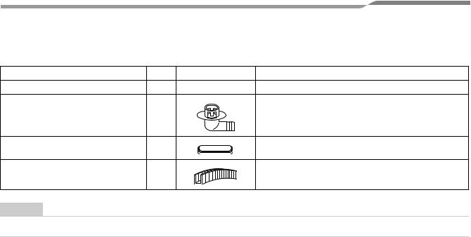
ACCESSORY PARTS |
|
||
|
Part name |
Q’ty |
Shape |
Usage |
Installation manual |
1 |
This manual |
(Hand this directly to the customer.) |
|
Drain nipple |
1 |
|
|
|
Waterproof rubber cap |
5 |
|
|
|
Edge Guard |
1 |
|
Protects piping against sharp edges |
|
NOTE
Use drain nipple and waterproof rubber cap as necessary.
3-EN |
– 3 – |
Outdoor Unit |
Installation Manual |
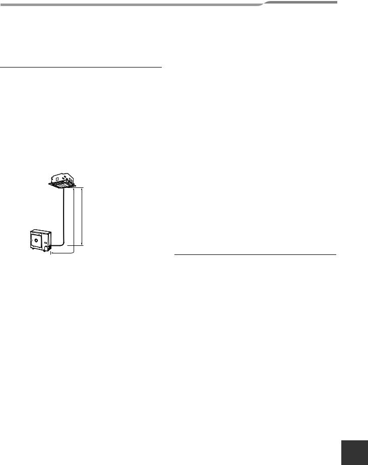
3 SYSTEM REQUIREMENTS
Piping (Field supplied)
•Minimum refrigerant line length between the outdoor unit and indoor unit is 16.5” (5 m)
•Maximum pipe lengths
Allowable |
Height difference |
Number of |
||
pipe length |
(Indoor-outdoor H) |
|||
bent portions |
||||
(ft (m)) |
(ft (m)) |
|||
|
||||
|
|
|
|
|
Total length |
Indoor unit: |
Outdoor unit: |
|
|
L |
Upper |
Lower |
10 or less |
|
164’1” (50) |
98’5” (30) |
98’5” (30) |
|
|
|
|
|
|
|
Figure of Single
Indoor Unit
Outdoor Unit
H
L
Refrigerant sizes
Liquid side |
Gas side |
|||
|
|
|
|
|
Outer |
Thickness |
Outer |
Thickness |
|
diameter |
diameter |
|||
|
|
|||
Ø3/8” |
0.03” |
Ø5/8” |
0.04” |
|
(9.5 mm) |
(0.8 mm) |
(15.9 mm) |
(1.0 mm) |
|
|
|
|
|
|
Flare nuts and flaring
•The flare nuts and flaring are different from those for the conventional refrigerant.
Use the flare nuts supplied with the air conditioner or those for R410A.
•Before performing flaring, carefully read “REFRIGERANT PIPING”
Insulation
Both lines need to be insulated. Use a minimum 0.4” (10 mm) wall thickness.
Refrigerant charge
Length of refrigerant |
Additional refrigerant |
|
pipe connected to |
||
indoor/outdoor unit |
|
|
16’5” - 98’5” |
None |
|
(5 - 30 m) |
||
|
||
|
|
|
*98’5” - 164’1” |
Add 0.43 oz/ft (40 g/m) of |
|
refrigerant for piping that exceeds |
||
(30 - 50 m) |
||
98’5” (30 m) up to 164’1” (50 m). |
||
|
||
|
|
*Caution during addition of refrigerant
Max. amount of additional refrigerant is 1.8 lbs (800 g).
Charge the refrigerant accurately. Overcharging may cause serious trouble with the compressor.
*Minimum refrigerant pipe is 16’5”(5 m).
This may cause a malfunction of the compressor or other devices.
Metering Device is an electronic EXV (PMV) in outdoor unit.
Connecting power and control cables (Field supplied)
•The main power is supplied to the outdoor unit. The field supplied connecting cables from the outdoor unit to the indoor unit consist for 4 wires and provides the power for the indoor unit as well as the communication signal between the outdoor and indoor unit.
•System interconnection wire size must be AWG12.
•Breaker must have a capacity specified in the following table.
•All wiring must comply with local electric codes and NEC (National Electric Code) or CEC (Canadian Electric Code).
Model RAV- |
SP240 |
|
|
Power supply |
208/230 V, 60 Hz |
|
|
MCA |
24 A |
|
|
MOCP (MAX Fuse/CB) |
40 A |
|
|
Breaker |
25 A |
|
|
System interconnection wires |
AWG12 |
|
|
MCA = Minimum Circuit Amps
MOCP =Maximum Over Protection Device Amps.
EN
– 4 – |
4-EN |

Outdoor Unit |
Installation Manual |
4 PRECAUTIONS FOR SAFETY
Installing, starting up, and servicing air--conditioning equipment can be hazardous due to system pressures, electrical components, and equipment location (roofs, elevated structures, etc.).
Only trained, qualified installers and service mechanics should install, start--up, and service this equipment. Untrained personnel can perform basic maintenance functions such as cleaning coils. All other operations should be performed by trained service personnel.
When working on the equipment, observe precautions in the literature and on tags, stickers, and labels attached to the equipment.
Follow all safety codes. Wear safety glasses and work gloves. Keep quenching cloth and fire extinguisher nearby when brazing. Use care in handling, rigging, and setting bulky equipment.
Read these instructions thoroughly and follow all warnings or cautions included in literature and attached to the unit. Consult local building codes and National Electrical Code (NEC) for special requirements. Recognize safety information. This is the safety--alert symbol  . When you see this symbol on the unit and in instructions or manuals, be alert to the potential for personal injury.Understand these signal words: DANGER, WARNING, and CAUTION. These words are used with the safety--alert symbol.
DANGER identifies the most serious hazards which will result in severe personal injury or death. WARNING signifies hazards which could result in personal injury or death. CAUTION is used to identify unsafe practices which may result in minor personal injury or product and property damage. NOTE is used to highlight suggestions which will result in enhanced installation, reliability, or operation.
 WARNING
•Ask an authorized dealer or qualified installation professional to install/maintain the air conditioner. Perform installation work properly according to the Installation Manual.
Inappropriate installation may result in water leakage, electric shock or fire.
•Be sure to ground the equipment
Improper grounding may cause an electric shock.
Do not connect ground wires to gas pipes, water pipes, lightning rods or ground wires for telephone wires.
•Turn off the main power supply switch or breaker before attempting any electrical work and maintenance.
Make sure all power switches are off. Failure to do so may cause electric shock. Use an exclusive power circuit for the air conditioner. Use the rated voltage.
•When moving the air conditioner for installation to another place, be very careful not to allow the specified refrigerant (R410A) to become mixed with any other gaseous body into the refrigeration cycle.
If air or any other gas mixes with the refrigerant, the gas pressure in the refrigeration cycle will become abnormally high and it may result in the pipe bursting or personal injuries.
•Do not modify this unit by removing any of the safety guards or by by-passing any of the safety interlock switches.
•Do not touch the intake or aluminium fins of the outdoor unit.
Doing so may result in injury.
•Tighten the flare nut with a torque wrench in the specified manner.
Excessive tightening of the flare nut may cause a crack in the flare nut after a long period, which may result in refrigerant leakage.
•Install the air conditioner securely in a location where the base can sustain the weight of the unit adequately.
•If refrigerant gas has leaked during the installation work, ventilate the room immediately.
If the leaked refrigerant gas comes in contact with fire, noxious gas may be generated.
•After the installation work, confirm that refrigerant gas does not leak.
If refrigerant gas leaks into the room and flows near a fire source, such as a cooking range, noxious gas may be generated.
•Electrical work must be performed by a qualified electrician in accordance with the NEC or local code. Make sure the air conditioner uses an exclusive power supply.
An insufficient power supply capacity or inappropriate installation may cause fire.
•Use only the specified wiring during the unit installation. Ensure that all terminals are securely fixed, so preventing any external forces having a negative effect on the terminals.
5-EN |
– 5 – |

Outdoor Unit |
Installation Manual |
 WARNING
•When the air conditioner cannot cool or heat a room well, contact the dealer from whom you purchased the air conditioner as refrigerant leakage is considered as the cause.
In the case of repair that requires refill of refrigerant, ask service personnel about details of the repair.
The refrigerant used in the air conditioner is harmless.
Generally, the refrigerant does not leak. However, if the refrigerant leaks in a room and a heater or stove burner in the room catches fire, it may generate toxic gas.
When you ask service personnel for repairing refrigerant leakage, confirm that the leakage portion has been completely repaired.
•Do not install the air conditioner in a location that may be subjected to a risk of exposure to a combustible gas.
If a combustible gas leaks and becomes concentrated around the unit, a fire may occur.
•Install the refrigerant pipe securely during the installation work before operating the air conditioner.
If the compressor is operated with the valve open and without the refrigerant pipe, the compressor sucks air and the refrigeration cycle is over pressurized, which may cause a burst or injury.
•When carrying out the pump-down work, shut down the compressor before disconnecting the refrigerant pipe.
Disconnecting the refrigerant pipe with the service valve left open and with the compressor still operating will cause air, etc. to be sucked in, raising the pressure inside the refrigeration cycle to an abnormally high level, and possibly resulting in rupturing, injury, etc.
 CAUTION
•Do not climb onto or place objects on top of the outdoor unit.
You may fall or the objects may fall off of the outdoor unit and result in injury.
•Wear heavy gloves during the installation work to avoid injury.
EQUIPMENT DAMAGE HAZARD
Failure to follow this caution may result in equipment damage or improper operation.
Do not bury more than 36 in. (914 mm) of refrigerant pipe in the ground. If any section of pipe is buried, there must be a 6 in. (152 mm) vertical rise to the valve connections on the outdoor units. If more than the recommended length is buried, refrigerant may migrate to the cooler buried section during extended periods of system shutdown. This causes refrigerant slugging and could possibly damage the compressor at start-up.
EN
– 6 – |
6-EN |
Outdoor Unit |
Installation Manual |
5 INSTALLATION OF NEW REFRIGERANT AIR CONDITIONER
 CAUTION
New Refrigerant Air Conditioner Installation
•THIS AIR CONDITIONER ADOPTS THE NEW HFC REFRIGERANT (R410A) WHICH DOES NOT DESTROY OZONE LAYER.
R410A refrigerant is apt to be affected by impurities such as water, oxidizing membrane, and oils because the working pressure of R410A refrigerant is approx. 1.6 times as that of refrigerant R22. Accompanied with the adoption of the new refrigerant, the refrigerant oil has also been changed. Therefore, during installation work, be sure that water, dust, former refrigerant, or refrigerant oil does not enter the new type refrigerant R410A air conditioner cycle.
To prevent mixing of refrigerant or refrigerant oil, the sizes of connecting sections of charging port on main unit and installation tools are different from those of the conventional refrigerant units. Accordingly, special tools are required for the new refrigerant (R410A) units. For connecting pipes, use new and clean piping materials with high pressure fittings made for R410A only, so that water and/or dust does not enter.
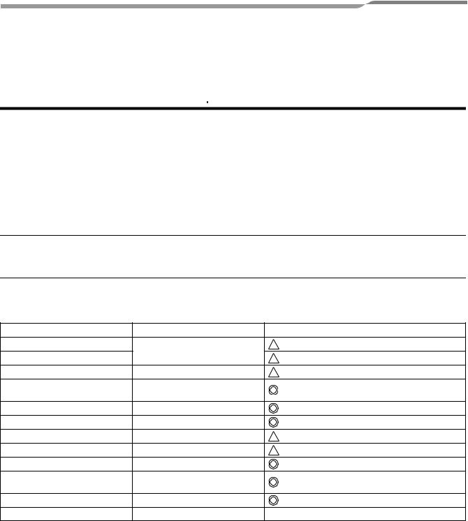
Required Tools/Equipment and Precautions for Use
Prepare the tools and equipment listed in the following table before starting the installation work.  : R410A exclusive
 : Generic
Tools/equipment |
Use |
|
Manifold gauge* |
Vacuuming/charging refrigerant |
|
Charging hose |
and operation check |
|
|
|
|
Gas leak detector |
Gas leak check |
|
Vacuum pump with backflow |
Vacuum drying |
|
prevention function |
|
|
|
|
|
Flare tool |
Flare machining of pipes |
Usable if dimensions are adjusted. |
Bender |
Bending pipes |
|
Refrigerant recovery equipment |
Refrigerant recovery |
|
Torque wrench |
Tightening flare nuts |
Ø1/2” (12.7 mm) and 5/8” (Ø15.9 mm) |
Pipe cutter |
Cutting pipes |
|
Brazing torch and nitrogen |
Braze pipes |
|
cylinder |
|
|
|
|
|
Refrigerant charging scales |
Charging refrigerant |
|
4 mm hexagon wrench |
Opening liquid valve |
|
7-EN |
– 7 – |
 Loading...