


B-SA4TP
Table of contents
 Loading...
TOSHIBA Thermal Printer
B-SA4TP SERIES
Owner's Manual
CE Compliance (for EU only)
A
A
This product complies with the requirements of EMC and Low Voltage Directives including their
amendments.
VORSICHT:
• Schallemission: unter 70dB (A) nach DIN 45635 (oder ISO 7779)
• Die für das Gerät Vorgesehene Steckdose muß in der Nähe des Gerätes und leicht zugänglich sein.
Centronics is a registered trademark of Centronics Data Computer Corp.
Microsoft is a registered trademark of Microsoft Corporation.
Windows is a trademark of Microsoft Corporation.
s an ENERGY STAR® Partner, TOSHIBA TEC has determined that this
product meets the ENERGY STAR
-- Outline of the International ENERGY STAR® Office Equipment Program --
The International ENERGY STAR
promotes energy saving through the penetration of energy efficient computers and other office
equipment. The program backs the development and dissemination of products with functions that
effectively reduce energy consumption. It is an open system in which business proprietors can
participate voluntarily. The targeted products are office equipment such as computers, monitors,
printers, facsimiles, copiers, scanners, and multifunction devices. Their standards and logos are
uniform among participating nations.
®
guidelines for energy efficiency.
®
Office Equipment Program is an international program that
E
NERGY STAR is a U.S. registered mark.
This equipment has been tested and found to comply with the limits for a Class A digital device,
pursuant to Part 15 of the FCC Rules. These limits are designed to provide reasonable rotection
against harmful interference when the equipment is operated in a commercial environment. This
equipment generates, uses, and can radiate radio frequency energy and, if not installed and sed in
accordance with the instruction manual, may cause harmful interference to radio communications.
Operations of this equipment in a residential area is likely to cause harmful interference in which case
the user will be required to correct the interference at his own expense.
Changes or modifications not expressly approved by manufacturer for compliance could void the
user’s authority to operate the equipment.
“This Class A digital apparatus meets all requirements of the Canadian Interference-Causing
Equipment Regulations.”
“Cet appareil numérique de la classe A respecte toutes les exigences du Règlement sur le matériel
brouilleur du Canada.”
N258
(for USA only)
(for CANADA only)
IP20
< For EU Only >
TOSHIBA TEC Europe Retail Information Systems S.A.
Rue de la Célidée 33 BE-1080 Brussels
Copyright © 2005
by TOSHIBA TEC CORPORATION
ll Rights Reserved
570 Ohito, Izunokuni-shi, Shizuoka-ken, JAPAN

Waste Recycling information for users:
Following information is only for EU-member states:
The use of the crossed-out wheeled bin symbol indicates that this product
may not be treated as general household waste.
By ensuring this product is disposed of correctly you will help prevent
potential negative consequences for the environment and human health, which could
otherwise be caused by inappropriate waste handling of this product. For more detailed
information about the take-back and recycling of this product, please contact your supplier
where you purchased the product.
Safety Summary
W
ENGLISH VERSION EO1-33048
Safety Summary
Personal safety in handling or maintaining the equipment is extremely important. Warnings and Cautions
necessary for safe handling are included in this manual. All warnings and cautions contained in this manual
should be read and understood before handling or maintaining the equipment.
Do not attempt to effect repairs or modifications to this equipment. If a fault occurs that cannot be rectified
using the procedures described in this manual, turn off the power, unplug the machine, then contact your
authorised TOSHIBA TEC representative for assistance.
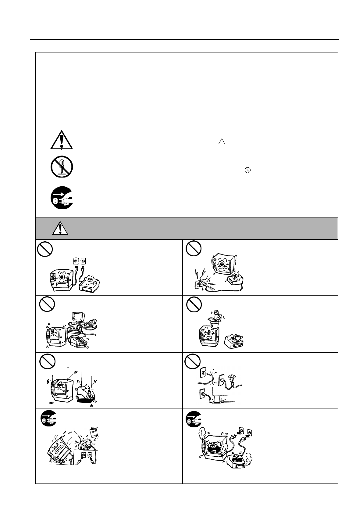
Meanings of Each Symbol
This symbol indicates warning items (including cautions).
Specific warning contents are drawn inside the
(The symbol on the left indicates a general caution.)
This symbol indicates prohibited actions (prohibited items).
Specific prohibited contents are drawn inside or near the
(The symbol on the left indicates “no disassembling”.)
This symbol indicates actions which must be performed.
Specific instructions are drawn inside or near the z symbol.
(The symbol on the left indicates “disconnect the power cord plug from the outlet”.)
symbol.
symbol.
Any other than the
specified AC voltage
is prohibited.
Prohibited
Prohibited
ARNING
Do not use voltages other than
the voltage (AC) specified on the
rating plate, as this may cause
fire or electric shock.
If the machines share the same
outlet with any other electrical
appliances that consume large
amounts of power, the voltage
will fluctuate widely each time
these appliances operate. Be sure
to provide an exclusive outlet for
the machine as this may cause
fire or electric shock.
Do not insert or drop metal,
flammable or other foreign
objects into the machines through
the ventilation slits, as this may
cause fire or electric shock.
This indicates that there is the risk of death or serious injury if the
machines are improperly handled contrary to this indication.
Prohibited
Prohibited
Prohibited
Do not plug in or unplug the power
cord plug with wet hands as this
may cause electric shock.
Do not place metal objects or
water-filled containers such as
flower vases, flower pots or mugs,
etc. on top of the machines. If
metal objects or spilled liquid enter
the machines, this may cause fire
or electric shock.
Do not scratch, damage or modify
the power cords. Also, do not
place heavy objects on, pull on, or
excessively bend the cords, as this
may cause fire or electrical shock.
Disconnect
the plug.
If the machines are dropped or
their cabinets damaged, first turn
off the power switches and
disconnect the power cord plugs
from the outlet, and then contact
your authorised TOSHIBA TEC
representative for assistance.
Continued use of the machine in
that condition may cause fire or
electric shock.
( )
i
Disconnect
the plug.
Continued use of the machines in
an abnormal condition such as
when the machines are producing
smoke or strange smells may cause
fire or electric shock. In these
cases, immediately turn off the
power switches and disconnect the
power cord plugs from the outlet.
Then, contact your authorised
TOSHIBA TEC representative for
assistance.
Safety Summary
ENGLISH VERSION EO1-33048
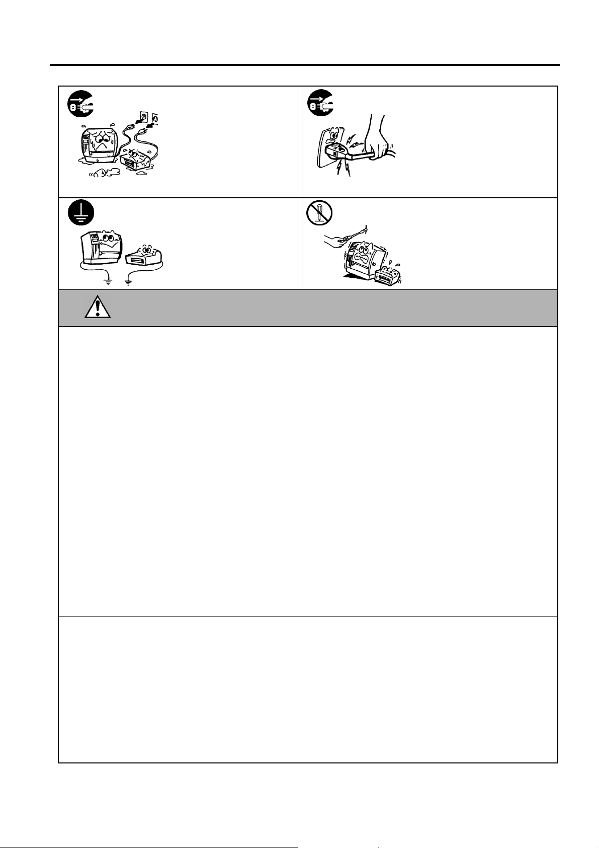
Disconnect
the plug.
Connect a
grounding wire.
If foreign objects (metal
fragments, water, liquids) enter
the machines, first turn off the
power switches and disconnect
the power cord plugs from the
outlet, and then contact your
authorised TOSHIBA TEC
representative for assistance.
Continued use of the machine in
that condition may cause fire or
electric shock.
Ensure that the equipment is
properly grounded. Extension
cables should also be grounded.
Fire or electric shock could
occur on improperly grounded
equipment.
Disconnect
the plug.
No
disassembling.
When unplugging the power cords,
be sure to hold and pull on the plug
portion. Pulling on the cord portion
may cut or expose the internal wires
and cause fire or electric shock.
Do not remove covers, repair or
modify the machine by yourself.
You may be injured by high
voltage, very hot parts or sharp
edges inside the machine.
This indicates that there is the risk of personal Injury or damage to
CAUTION
objects if the machines are improperly handled contrary to this indication.
Precautions
The following precautions will help to ensure that this machine will continue to function correctly.
•
Try to avoid locations that have the following adverse conditions:
* Temperatures out of the specification * Direct sunlight * High humidity
* Shared power source * Excessive vibration * Dust/Gas
•
The cover should be cleaned by wiping with a dry cloth or a cloth slightly dampened with a mild
detergent solution. NEVER USE THINNER OR ANY OTHER VOLATILE SOLVENT on the plastic
covers.
•
USE ONLY TOSHIBA TEC SPECIFIED paper and ribbons.
•
DO NOT STORE the paper or ribbons where they might be exposed to direct sunlight, high
temperatures, high humidity, dust, or gas.
•
Ensure the printer is operated on a level surface.
•
Any data stored in the memory of the printer could be lost during a printer fault.
•
Try to avoid using this equipment on the same power supply as high voltage equipment or equipment
likely to cause mains interference.
•
Unplug the machine whenever you are working inside it or cleaning it.
•
Keep your work environment static free.
•
Do not place heavy objects on top of the machines, as these items may become unbalanced and fall
causing injury.
•
Do not block the ventilation slits of the machines, as this will cause heat to build up inside the machines
and may cause fire.
•
Do not lean against the machine. It may fall on you and could cause injury.
•
Care must be taken not to injure yourself with the printer paper cutter.
•
Unplug the machine when it is not used for a long period of time.
•
Place the machine on a stable and level surface.
Request Regarding Maintenance
•
Utilize our maintenance services.
After purchasing the machine, contact your authorised TOSHIBA TEC representative for assistance
once a year to have the inside of the machine cleaned. Otherwise, dust will build up inside the machines
and may cause a fire or a malfunction. Cleaning is particularly effective before humid rainy seasons.
•
Our preventive maintenance service performs the periodic checks and other work required to maintain
the quality and performance of the machines, preventing accidents beforehand.
For details, please consult your authorised TOSHIBA TEC representative for assistance.
•
Using insecticides and other chemicals
Do not expose the machines to insecticides or other volatile solvents. This will cause the cabinet or
other parts to deteriorate or cause the paint to peel.
( )
ii


ENGLISH VERSION EO1-33048
TABLE OF CONTENTS
Page
1. PRODUCT OVERVIEW......................................................................................................... E1- 1
1.1 Introduction................................................................................................................... E1- 1
1.2 Features ....................................................................................................................... E1- 1
1.3 Accessories ................................................................................................................. E1- 2
1.4 Appearance..................................................................................................................E1- 3
1.4.1 Dimensions................................................................................................................E1- 3
1.4.2 Front View.................................................................................................................E1- 3
1.4.3 Rear View..................................................................................................................E1- 3
1.4.4 Operation Panel.........................................................................................................E1- 4
1.4.5 Interior.......................................................................................................................E1- 4
1.5 Options................................................................................................................................E1- 5
2. PRINTER SETUP.................................................................................................................. E2- 1
2.1 Installation .................................................................................................................... E2- 2
2.2 Connecting the Power Cord ......................................................................................... E2- 2
2.3 Loading the Media........................................................................................................ E2- 3
2.4 Loading the Ribbon ..................................................................................................... E2-11
2.5 Connecting the Printer to Your Host Computer........................................................... E2-14
2.6 Turning the Printer ON ................................................................................................ E2-15
2.7 Setting an Operating Environment .............................................................................. E2-16
2.7.1 How to Enter the System Mode................................................................................E2-17
2.7.2 Parameter Setting.....................................................................................................E2-17
2.7.3 IP Address Setting (TCP/IP).....................................................................................E2-24
2.8 Installing the Printer Drivers ........................................................................................ E2-30
2.8.1 Introduction...............................................................................................................E2-30
2.8.2 General Description..................................................................................................E2-30
2.8.3 Installing the Printer Driver .......................................................................................E2-31
2.8.4 Uninstalling the Printer Driver...................................................................................E2-43
2.8.5 Adding/Deleting a LAN Port......................................................................................E2-44
2.8.6 Cautions...................................................................................................................E2-46
2.8.7 Using the Printer Driver............................................................................................E2-47
2.9 Print Test ..................................................................................................................... E2-48
2.10 Position and Print Tone Fine Adjustment ................................................................... E2-50
2.11 Threshold Setting ........................................................................................................ E2-59
3. ON LINE OPERATION.......................................................................................................... E3- 1
3.1 Operation Panel............................................................................................................ E3- 1
3.2 Operation...................................................................................................................... E3- 2
3.3 Reset............................................................................................................................ E3- 2
4. MAINTENANCE .................................................................................................................... E4- 1
4.1 Cleaning ....................................................................................................................... E4- 1
4.1.1 Print Head/Platen/Sensors........................................................................................E4- 1
4.1.2 Covers and Panels....................................................................................................E4- 2
4.1.3 Optional Cutter Module..............................................................................................E4- 3
4.1.4 Optional Strip Module................................................................................................E4- 4

ENGLISH VERSION EO1-33048
y
5. TROUBLESHOOTING .......................................................................................................... E5- 1
5.1 Error Messages............................................................................................................ E5- 1
5.2 Possible Problems........................................................................................................ E5- 3
5.3 Removing Jammed Media............................................................................................ E5- 4
6. PRINTER SPECIFICATIONS................................................................................................ E6- 1
7. SUPPLY SPECIFICATIONS ................................................................................................. E7- 1
7.1 Media............................................................................................................................ E7- 1
7.1.1 Media Type......................................................................................................... E7- 1
7.1.2 Detection Area of the Transmissive Sensor....................................................... E7- 2
7.1.3 Detection Area of the Reflective Sensor............................................................. E7- 3
7.1.4 Effective Print Area............................................................................................. E7- 3
7.2 Ribbon.......................................................................................................................... E7- 4
7.3 Recommended Media and Ribbon Types .................................................................... E7- 4
7.4 Care/Handling of Media and Ribbon ............................................................................ E7- 5
APPENDIX 1 MESSAGES AND LEDS......................................................................................EA1-1
APPENDIX 2 INTERFACE.........................................................................................................EA2-1
APPENDIX 3 POWER CORD ....................................................................................................EA3-1
APPENDIX 4 PRINT SAMPLES ................................................................................................EA4-1
APPENDIX 5 GLOSSARIES......................................................................................................EA5-1
INDEX
WARNING!
This is a Class A product. In a domestic environment this product may cause radio interference in
which case the user ma
CAUTION!
1. This manual may not be copied in whole or in part without prior written permission of TOSHIBA
TEC.
2. The contents of this manual may be changed without notification.
3. Please refer to your local Authorised Service representative with regard to any queries you may
have in this manual.
be required to take adequate measures.

1. PRODUCT OVERVIEW
ENGLISH VERSION EO1-33048
1. PRODUCT OVERVIEW
1.1 Introduction
1.2 Features
Thank you for choosing the TOSHIBA B-SA4TP series thermal printer.
This Owner’s Manual contains from general set-up through how to
confirm the printer operation using an online test print, and should be
read carefully to help gain maximum performance and life from your
printer. For most queries please refer to this manual and keep it safe for
future reference. Please contact your TOSHIBA TEC representative for
further information concerning this manual.
This printer has the following features:
•
Space-saving design
An area required to place a printer is about A4 size, in spite of both
media and ribbon being loaded inside it. Also, the Top Cover is opened
upward, which saves the installation space.
The optional cutter module and strip module are as slim and small as
the Front Cover.
•
Various kinds of interface
Various kinds of interface are provided:
<Standard> <Option>
•
Parallel
•
USB
•
Built-in LAN
•
Superior hardware
Clear print is realized by an 8 dots/mm (203 dpi) (B-SA4TP-GS12) or
11.8 dots/mm (300 dpi) (B-SA4TP-TS12) print head, at a printing
speed of 50.8 mm/sec. (2 inches/sec.), 101.6 mm/sec. (4 inches/sec.), or
152.4 mm/sec. (6 inches/sec.)
•
Easy maintenance
Design of the printer is simple. Especially, attachment and removal of
the print head and platen are very simple, which makes maintenance
easy.
•
A variety of options
The following optional devices are available:
•
Cutter module
•
Strip module
•
Serial interface board
•
Wireless LAN board
•
RFID module
•
300-dpi print head
•
Serial
•
Wireless LAN
•
RFID
1.1 Introduction
E1- 1
1. PRODUCT OVERVIEW
A
ENGLISH VERSION EO1-33048
1.3 Accessories
s a power cord is not supplied
with this printer, please purchase
one that meets each country’s
safety standard. For details, refer
to APPENDIX 3.
NOTE:
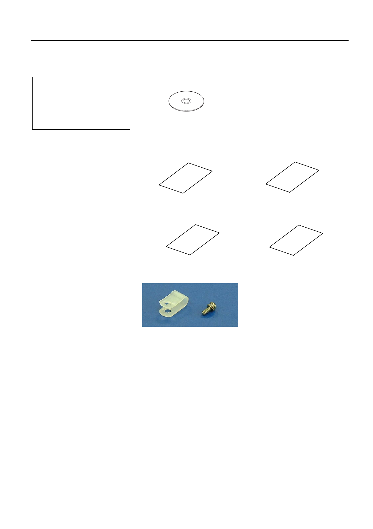
1.3 Accessories
When unpacking the printer, please make sure all the following
accessories are supplied with the printer.
Start-up
Supply Loading Instructions
(Doc. No.: EO2-33017)
CD-ROM (1 pc.)
<Contents>
• Bar code print application (Bartender ultra lite)
• Windows Driver
• Owner’s Manual
• Specifications (Programming, Key operation, etc.)
• Product information (Catalogue)
Safety Precautions
(Doc. No.: EO2-33016)
Quality Control Report
(1 sheet)
Warranty Disclaimer Sheet
(1 sheet)
Cable Clamp (1 pc.)
SMW-3x8 Screw (1 pc.)
E1- 2
1. PRODUCT OVERVIEW
ENGLISH VERSION EO1-33048
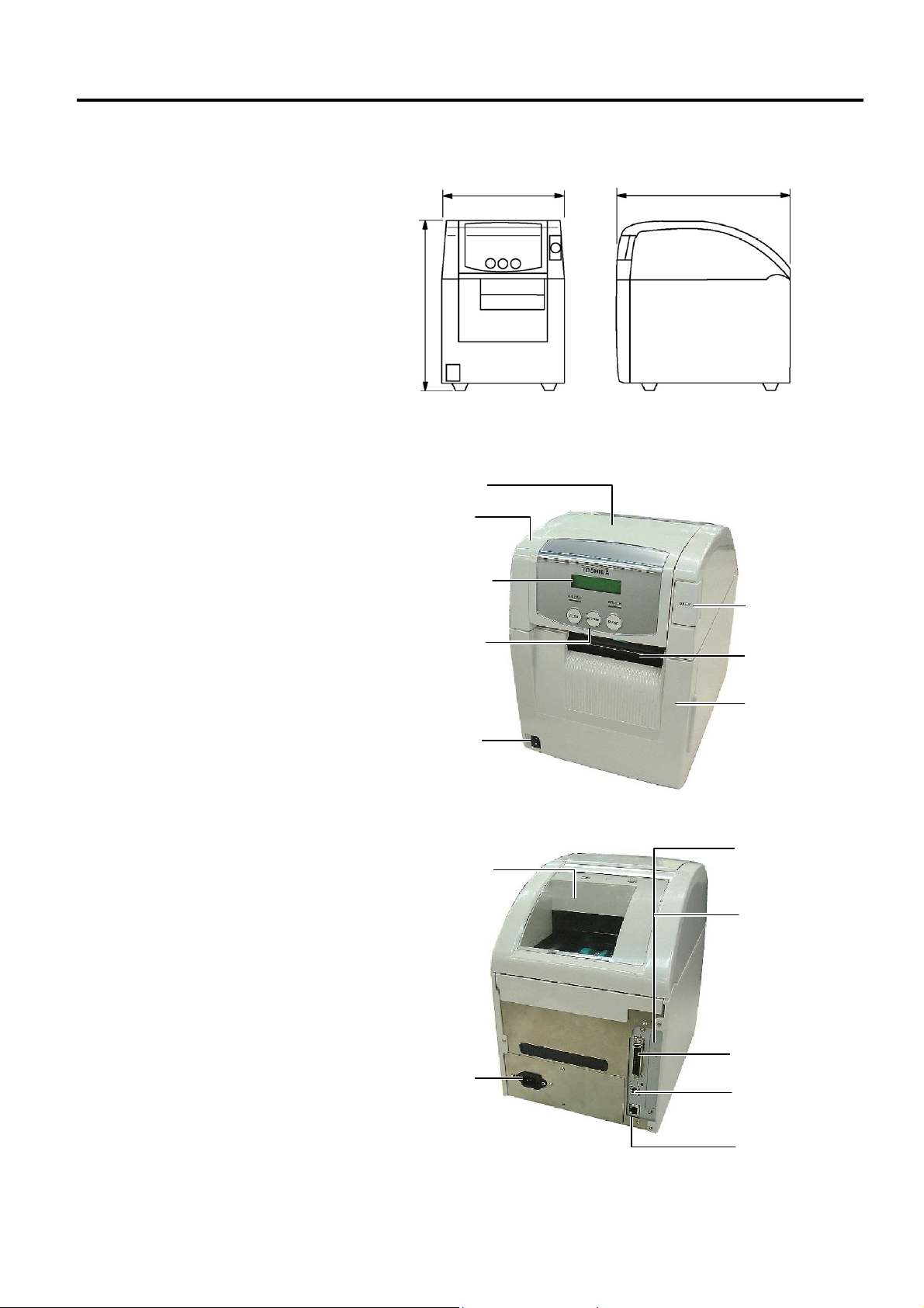
1.4 Appearance
1.4.1 Dimensions
1.4.2 Front View
1.4 Appearance
The names of the parts or units introduced in this section are used in the
following chapters.
332
(13.1)
238 (9.4)
339 (13.3)
Dimensions in mm (inches)
Ribbon Cover
Top Cover
1.4.3 Rear View
LCD Message
Display
Operation Panel
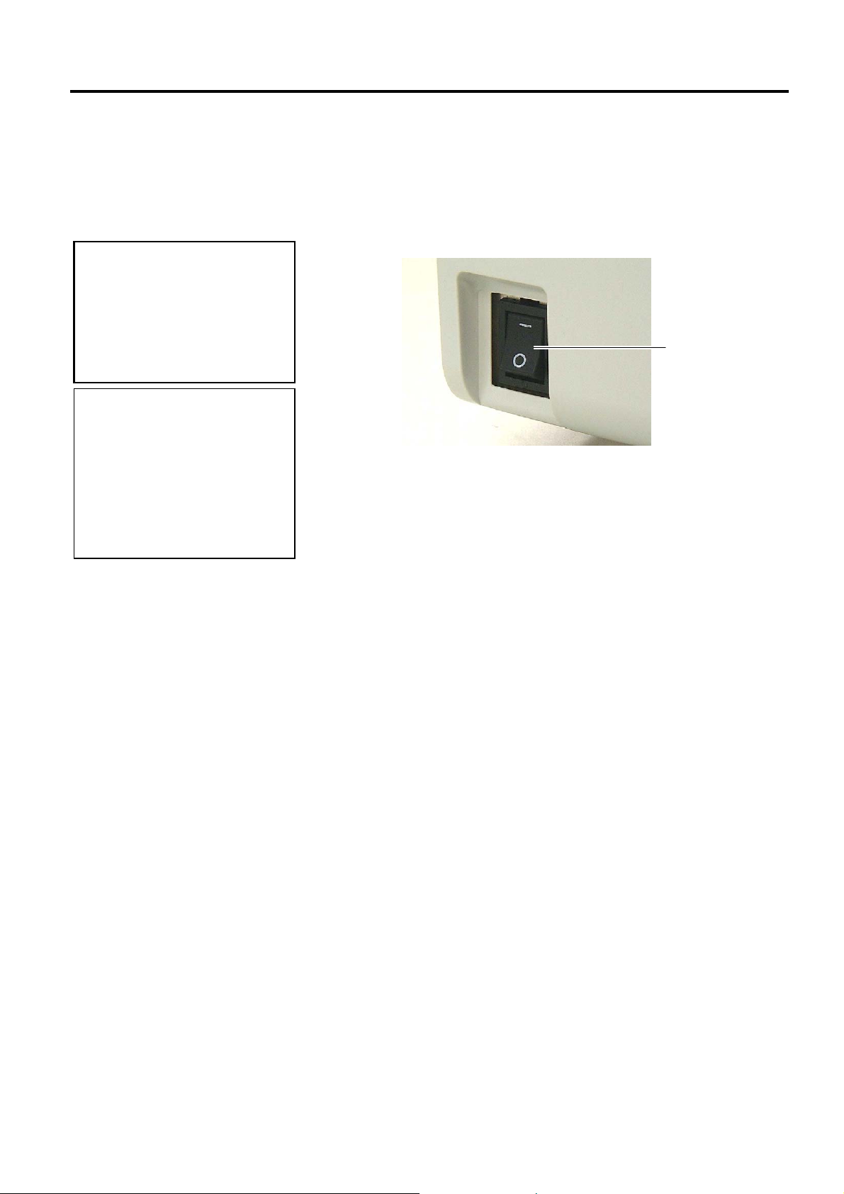
Power Switch
O: OFF
I: ON
Top Cover
Release Button
Media Outlet
Front Cover
Supply Window
RS-232C Serial
Interface Connector
(Option)
Wireless LAN
Interface Board
(Option)
AC Power Inlet
E1- 3
Parallel Interface
Connector
(Centronics)
USB Interface
Connector
LAN Interface
Connector
1. PRODUCT OVERVIEW
r
r
r
ENGLISH VERSION EO1-33048
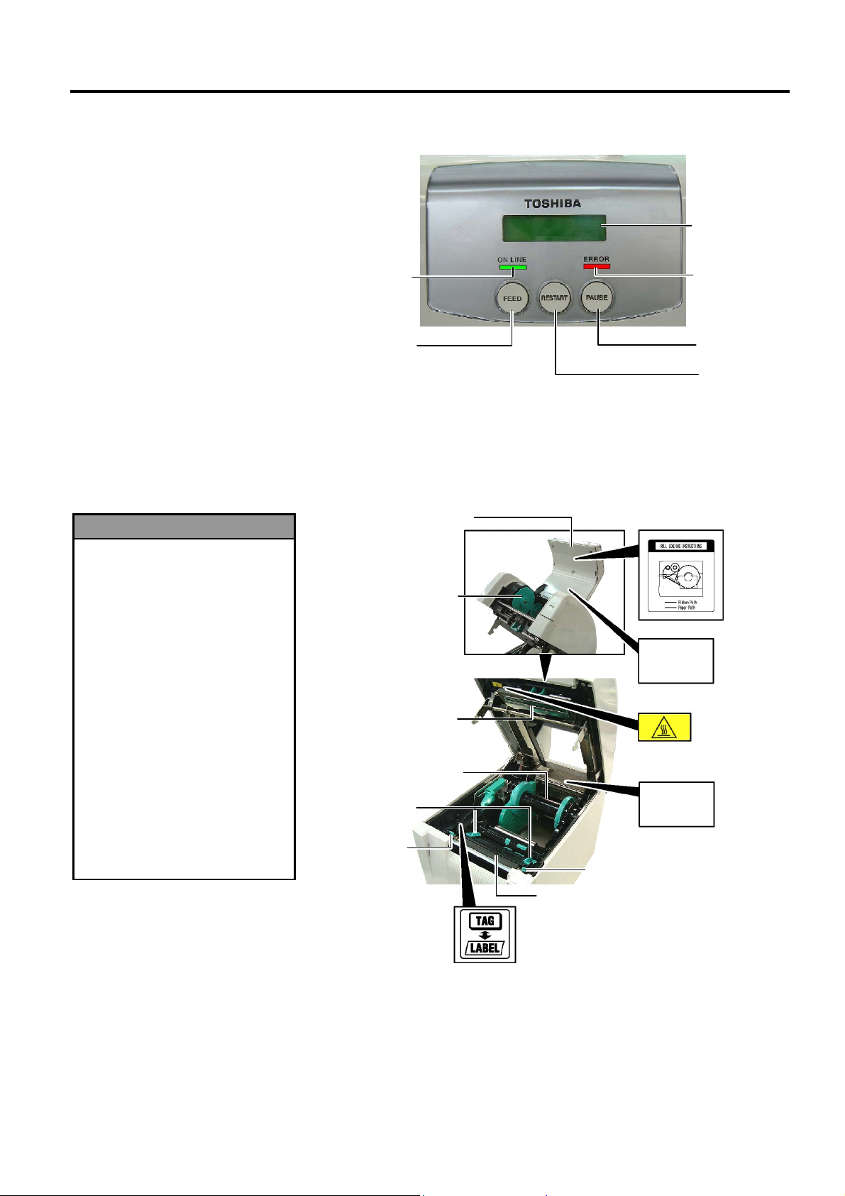
1.4.4 Operation Panel
1.4.5 Interior
1. Do not touch the Print Head
or around it just after
printing. You may get
burned as the Print Head
becomes very hot during
printing.
2. Do not touch any moving
parts. To reduce the risk of
fingers, jewellery, clothing,
etc., being drawn into the
moving parts, be sure to
load the media once the
printer has stopped moving
completely.
3. To avoid injury, be careful
not to trap your fingers
while opening or closing the
cover.
WARNING!
1.4 Appearance
LCD Message
Display
ON LINE LED
(Green)
[FEED] key
Please see Section 3.1 for further information about the Operation Panel.
Media Holder Ass’y
Media Guide
Head Position
Ribbon Cove
Ribbon Stoppe
(Take-up side)
Print Head
Leve
Supply Path Label
Caution
Label
Caution
Label
Head Position Lever
Platen
ERROR LED
(Red)
[PAUSE] key
[RESTART] key
Caution about the
moving parts
(Please refer to
WARNING 2.)
Caution symbol for
the print head (Please
refer to WARNING 1)
Caution about the
cover open/close
(Please refer to
WARNING 3.)
Head Position Label
(Refer to Section 2.3 Loading
the Media, Step 13.)
E1- 4

1. PRODUCT OVERVIEW
ENGLISH VERSION EO1-33048
1.5 Options
Option Name Type Usage
300-dpi Print
Head
Cutter module B-SA204-QM-R
Strip module B-SA904-H-QM-R
Serial Interface
Board
Wireless LAN
Board
RFID module B-SA704-RFID-U1-US
B-SA704-TPH3-QM-R This print head enables a conversion of a 203-dpi print head of the
B-SA4TM-GS12/B-SA4TP-GS12 model into a 300-dpi print head.
This option is intended for use when you desire to print Kanji
(Chinese characters) or to obtain clearer print.
A cutter which cuts the media one by one. This module is slim and
compact enough to be fitted in the Front Cover.
This module peels off a printed label from the backing paper at the
media outlet. It is slim and compact enough to be fitted in the Front
Cover.
B-SA704-RS-QM-R
Installing this PC board provides an RS232C interface port.
B-SA704-WLAN-QM Installing this PC board allows a communication by wireless LAN.
Installing this module enables read and write of RFID tags.
B-SA704-RFID-U1-EU
B-SA704-RFID-H1-QM
Applicable frequency range differs depending on the module types:
U1-US: UHF, 902MHz to 928MHz
U1-EU: UHF, 869.5MHz
H1-QM: HF, 13.56MHz
1.5 Options
E1- 5
2. PRINTER SETUP
t
g
p
p
j
p
ENGLISH VERSION EO1-33048
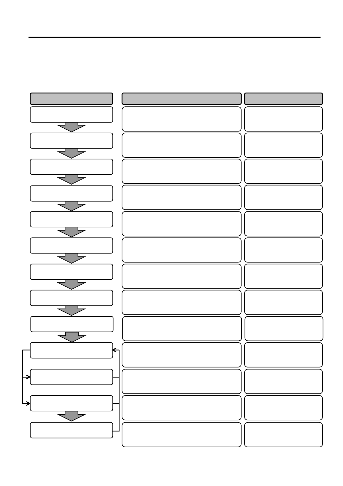
2. PRINTER SETUP
2. PRINTER SETUP
This section outlines the procedures to setup your printer prior to its operation. The section includes precautions,
loading media and ribbon, connecting cables, setting the operating environment of the printer, and performing an
online print test.
Installation
Connecting the power cord
Loading the media
Media sensor position
nment
ali
After referring to the Safety Precautions in
this manual, install the printer on a safe and
stable location.
Connect a power cord to the power inlet of
the printer, then, to an AC outlet.
Load a label stock or tag stock.
Adjust the position of feed gap sensor or
black mark sensor according to the media to
be used.
2.1 Installation
2.2 Connecting the Power
2.3 Loading the Media
2.3 Loading the Media
Reference Procedure Setup Flow
Cord
Loading the ribbon
Connecting to a host computer
Turning the power ON
Setting the operating
environmen
Installing the printer driver
Print test
Position and Print Tone Fine
ustment
ad
In case of thermal transfer printing, load the
ribbon.
Connect the printer to a host computer or a
network.
Turn on the printer power.
Set the printer parameters in the system
mode.
If necessary, install the printer driver in your
host computer.
Make a print test in your operating
environment and check the print result.
If necessary, fine adjust the print start
osition, cut/strip position, print tone, etc.
2.4 Loading the Ribbon
2.5 Connecting the Printer to
Your Host Computer
2.6 Turning the Power ON
2.7 Setting an Operating
Environment
2.8 Installing the Printer
Drivers
2.9 Print Test
2.10 Position and Print Tone
Fine Adjustment
Automatic threshold setting
If the print start position cannot be detected
roperly when pre-printed label is used, set
2.11 Threshold Setting
the threshold automatically.
Manual threshold setting
If the print start position cannot be detected
roperly even an automatic threshold setting
2.11 Threshold Setting
is performing, manually set the threshold.
E2- 1
2. PRINTER SETUP
A
A
ENGLISH VERSION EO1-33048
2.1 Installation
s the enclosure of this product
is made from plastic, do not
install the printer where it might
be exposed to oil or solvent.
CAUTION!
2.2 Connecting the
Power Cord
s a Power Cord is not supplied
with the printer, please purchase
an approved on that meets the
safety standard of each country.
(Refer to APPENDIX 3.)
CAUTION!
2.2 Connecting the Power Cord
To insure the best operating environment, and to assure the safety of the
operator and the equipment, please observe the following precautions.
• Operate the printer on a stable, level, operating surface in a location
free from excessive humidity, high temperature, dust, vibration or
direct sunlight.
• Keep your work environment static free. Static discharge can cause
damage to delicate internal components.
• Make sure that the printer is connected to a clean source of AC
Power and that no other high voltage devices that may cause line
noise interference are connected to the same mains.
• Assure that the printer is connected to the AC mains with a threeprong power cable that has the proper ground (earth) connection.
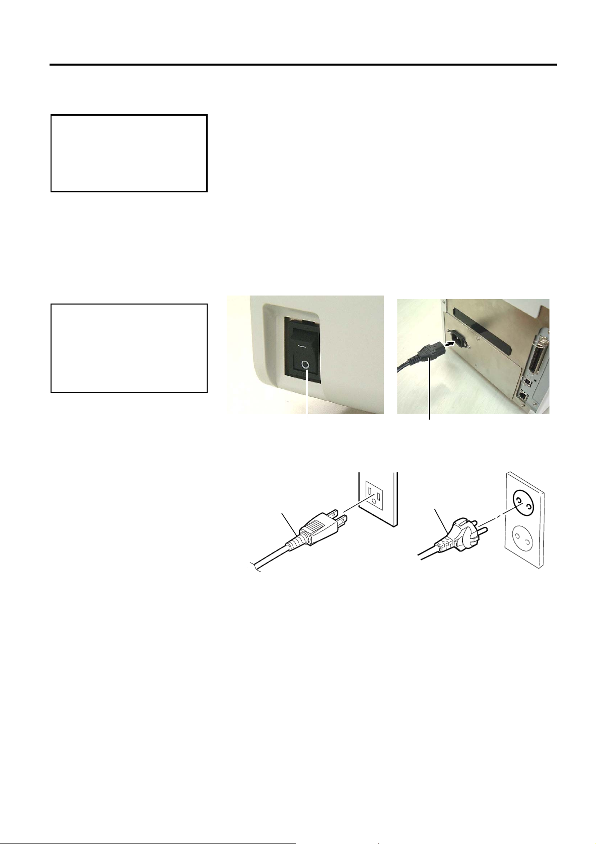
{
1. Make sure that the printer Power Switch is in the OFF (
Connect the Power Cord to the printer as shown in the figure below
2. Plug the other end of the Power Cord into a grounded outlet as shown
[Example of US Type] [Example of EU Type]
Power Switch
in the figure below.
Power Cord
Power Cord
Power Cord
) position.
E2- 2
2. PRINTER SETUP
A
ENGLISH VERSION EO1-33048
2.3 Loading the Media
1. Do not touch any moving
parts. To reduce the risk of
fingers, jewellery, clothing,
etc., being drawn into the
moving parts, be sure to load
the media once the printer
has stopped moving
completely.
2. The Print Head becomes hot
immediately after printing.
the media.
3. To avoid injury, be careful
not to trap your fingers while
opening or closing the cover.
1. Make sure that the Upper
Sensor Ass’y is closed when
taking out the Media Holder
Ass’y. If the Upper Sensor
Ass’y is opened, it may be
damaged.
2. Be careful not to touch the
Print Head Element when
opening the Top Cover.
Failure to do this may cause
missing dots by static
electricity or other print
quality problems.
WARNING!
llow it to cool before loading
CAUTION!
2.3 Loading the Media
The following procedure shows the steps to properly load the media into
the printer so that it feeds straight and true through the printer.
Use the same procedure when replacing the media, also.
The printer prints both labels and tags.
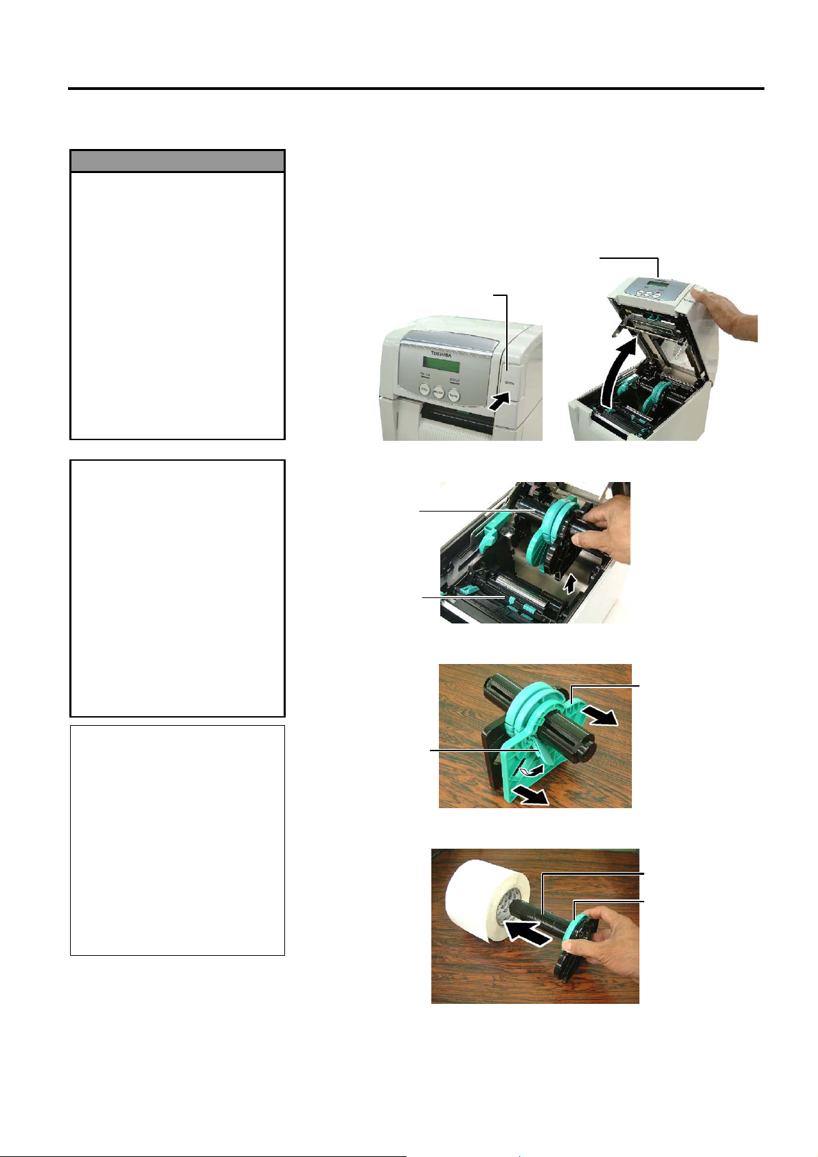
1. Press the Top Cover Release Button and gently open the Top Cover to
its fully open position supporting it with your hand.
Top Cover Release Button
Top Cover
2. Take out the Media Holder Ass’y from the printer.
Media Holder
Ass’y
Upper Sensor
Ass’y
3. Raise the Release Lever and remove the Media Holder (Left).
Media Holder (Left)
NOTE:
1. As the Top Cover is heavy, be
sure to support it with your
hand when opening it. Failure
to do this may cause the printer
to fall over backward.
2. For the specification of
available media, refer to
Section 7.1 Media.
When the inner core diameter
3.
of the media roll is 40 mm,
remove the Spacers from the
Media Holders.
Release Lever
4. Insert the Media Shaft into the core of a media roll.
Media Shaft
Spacer
E2- 3
2. PRINTER SETUP
B
r
p
ENGLISH VERSION EO1-33048
2.3 Loading the Media
(Cont.)
2.3 Loading the Media
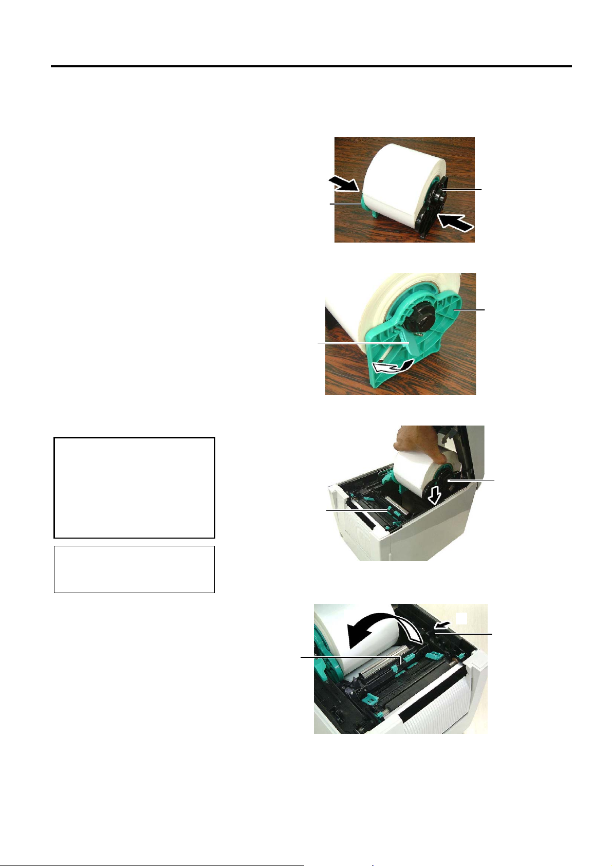
5. Put the Media Holder (Left) onto the Media Shaft. Push the Media
Holder (Left) and the Media Holder (Right) against the media until the
media is held firmly in place. This will automatically centre the
media.
Media Holder (Right)
Media Holder (Left)
6. Fold the Release Lever to lock the Media Holder (Left).
Media Holder (Left)
Release Leve
CAUTION!
Make sure that the Upper
Sensor Ass’y is closed when
lacing the Media Holder Ass’y
into the printer. If the Upper
Sensor Ass’y is opened, it may
be damaged.
NOTE:
e careful of the orientation of the
Media Holder Ass’y and the media.
7. Place the Media Holder Ass’y into the printer.
Media Holder Ass’y
Upper Sensor
Ass’y
8. Slightly push the Upper Sensor Lever inside (c), and open the Upper
Sensor Ass’y (d).
d
Upper Sensor
Ass’y
c
Upper Sensor Lever
E2- 4
2. PRINTER SETUP
A
p
A
ENGLISH VERSION EO1-33048
2.3 Loading the Media
(Cont.)
CAUTION!
Be sure to close the Upper
Sensor Ass’y before closing the
Top Cover. If the Upper Sensor
ss’y is opened, it may be
damaged.
NOTE:
Make sure that the Upper Sensor
ss’y is locked. If it is unlocked, a
aper jam or print failure may
occur.
2.3 Loading the Media
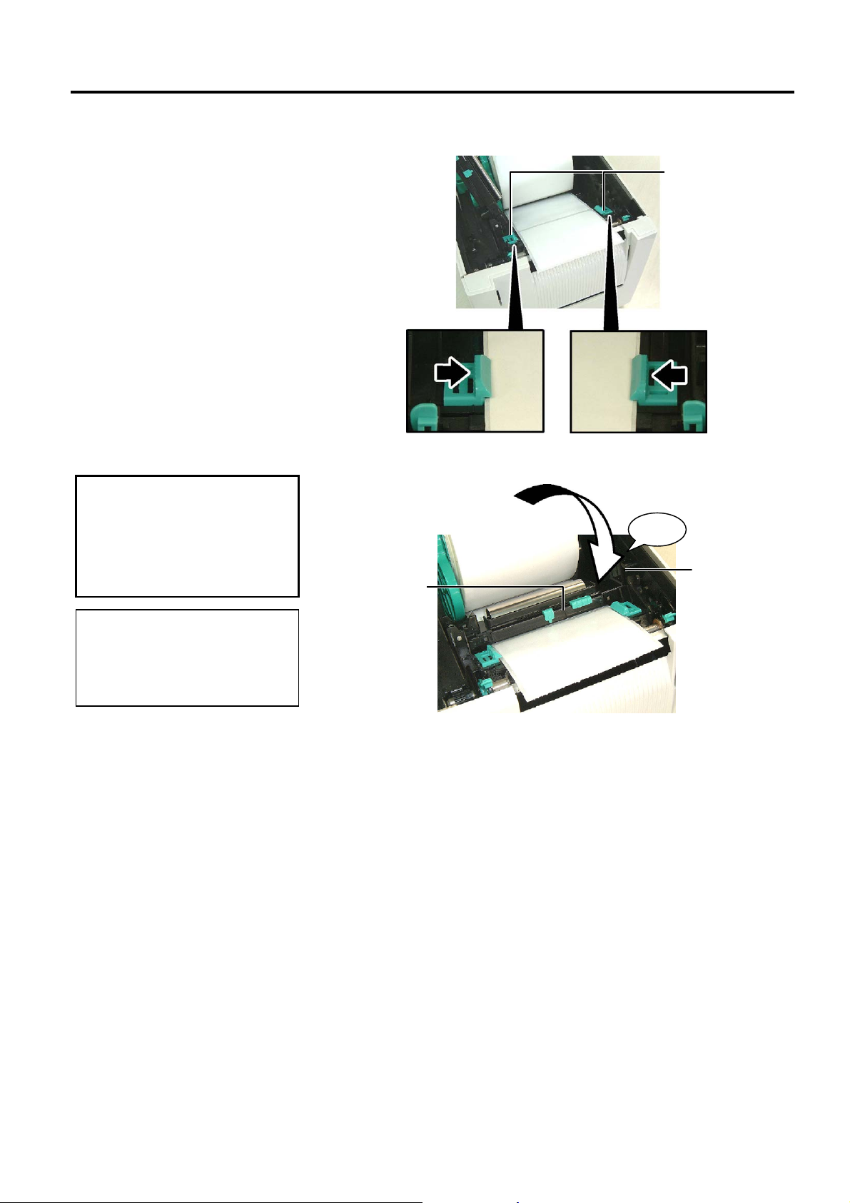
9. Pull the media out of the front of the printer, and adjust the Media
Guides to the media width. This will automatically centre the media.
Media Guide
10. Lower the Upper Sensor Ass’y until the Upper Sensor Lever clicks
into position.
Click
Upper Sensor
Upper Sensor
Ass’y
Lever
E2- 5
2. PRINTER SETUP
B
ENGLISH VERSION EO1-33048
2.3 Loading the Media
(Cont.)
2.3 Loading the Media
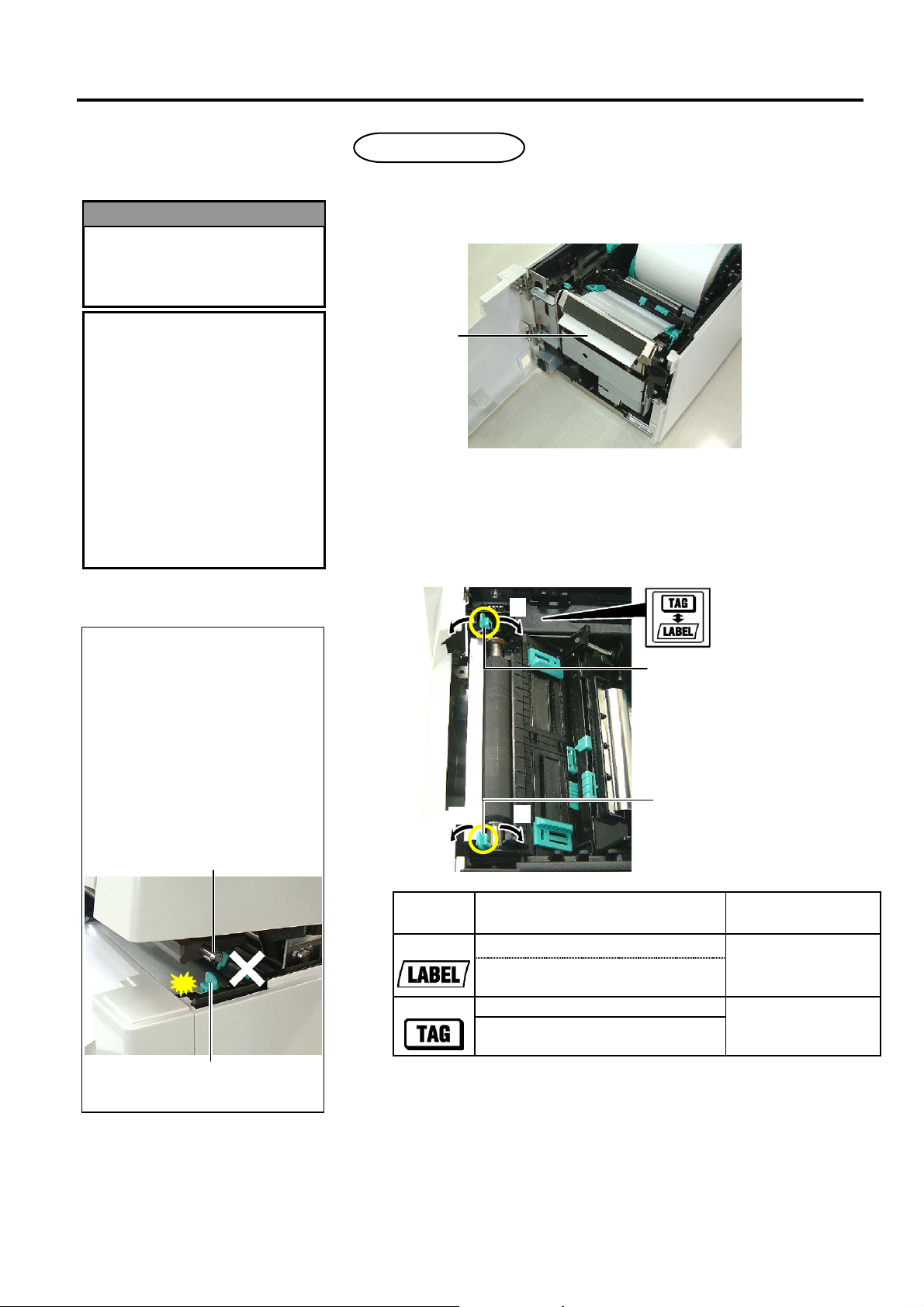
11. After loading the media, it may be necessary to set the position of
the Media Sensor used to detect the print start position for label or
tag printing.
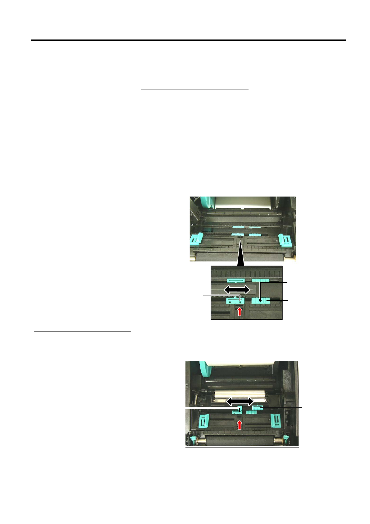
Setting the Feed Gap Sensor position
When using a label stock without black marks, the Feed Gap Sensor is
used to detect a print start position.
(1) Push the Upper Sensor Lever inside and open the Upper Sensor
Ass’y.
(2) Slide the Lower Sensor Tab with your finger to move the Feed Gap
Sensor so that the Feed Gap Sensor is positioned at the centre of the
labels. ( { indicates the position of the Feed Gap Sensor).
It may be easier to move the Lower Sensor Tab if you use a pen
inserting its tip into the pinhole of the tab.
It may be easier to move the Lower Sensor Tab if you use a pen
inserting its tip into the pinhole of the tab.
NOTE:
e sure to align the Upper Feed
Gap Sensor with the Lower Feed
Gap Sensor. Failure to do this
cause a paper jam error.
Pinhole
Feed Gap
Sensor
Lower Sensor Tab
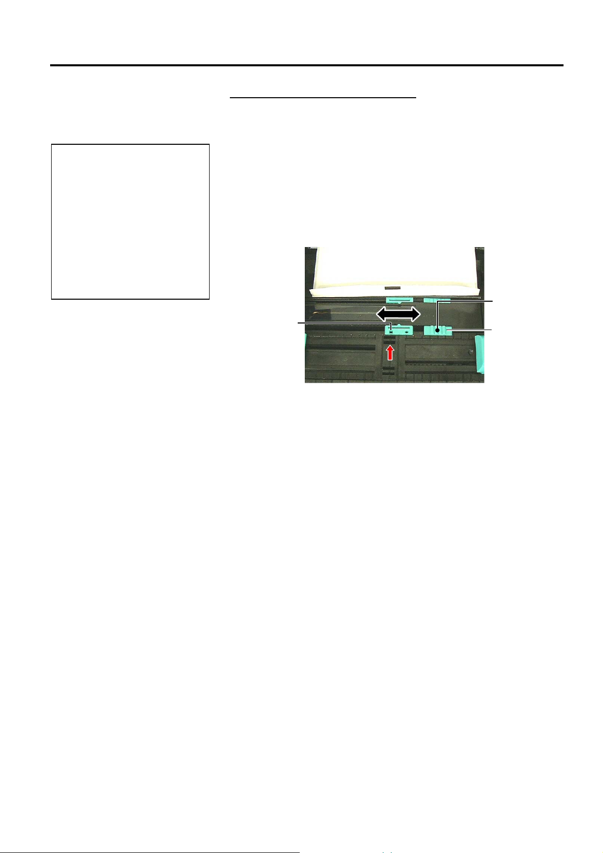
(3) Lower the Upper Sensor Ass’y until the Upper Sensor Lever clicks
into position.
(4) Slide the Upper Sensor Tab to move the Feed Gap Sensor so that it
aligns with the lower Feed Gap Sensor.
Feed Gap
Sensor
Upper Sensor
Tab
E2- 6
2. PRINTER SETUP
ENGLISH VERSION EO1-33048
2.3 Loading the Media
(Cont.)
1. Be sure to set the Black Mark
Sensor to detect the centre of the
black mark, otherwise a paper
jam or no paper error may
occur.
2. After adjusting the Black Mark
Sensor position, align the Upper
Feed Gap Sensor with the
Lower Feed Gap Sensor. This is
because a paper end is detected
by the Feed Gap Sensor.
NOTES:
2.3 Loading the Media
Setting the Black Mark Sensor position
When using media with black marks, the Black Mark Sensor is used to
detect a print start position.
(1) Push the Upper Sensor Lever inside and open the Upper Sensor
Ass’y.
(2) Check the reverse side of the media for the black mark position.
(3) Slide the Lower Sensor Tab to move the Black Mark Sensor so that
it is in line with the centre of the black mark on the media.
( indicates the position of the Black Mark Sensor).
It may be easier to move the Lower Sensor Tab if you use a pen
inserting its tip into the pinhole of the tab.
Pinhole
Black Mark
Sensor
Lower Sensor
Tab
(4) Lower the Upper Sensor Ass’y until the Upper Sensor Lever clicks
in position.
E2- 7
2. PRINTER SETUP
)
j
ENGLISH VERSION EO1-33048
2.3 Loading the Media
(Cont.)
2.3 Loading the Media
12. There are three issue modes available on this printer. How to set the
media for each mode is provided below.
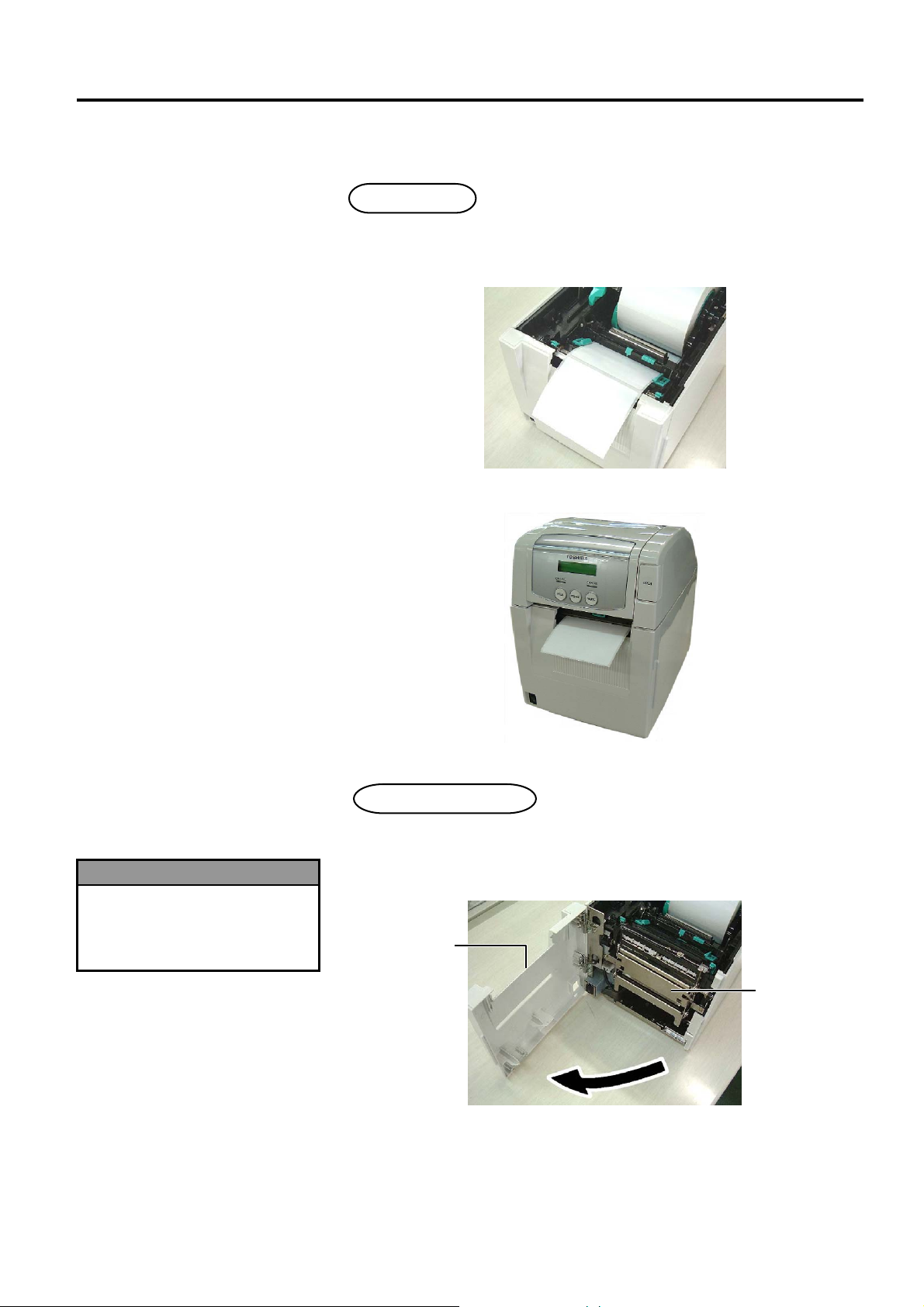
Batch mode
In the batch mode, the media is continuously printed and fed until the
number of labels/tags specified in the issue command have been printed.
(1) Pull the top edge of the media past the Platen.
(2) Close the Top Cover until it clicks.
WARNING!
Be careful that your fingers,
ewellery, clothing, etc., are not
draw into the rollers of the Strip
Unit.
Strip mode (Option
When the optional Strip Module is fitted, a label is automatically
removed from the backing paper at the Strip Plate as each label is printed.
(1) Open the Front Cover holding its right side.
Front Cover
Strip Unit
E2- 8
2. PRINTER SETUP
B
ENGLISH VERSION EO1-33048
2.3 Loading the Media
(Cont.)
e sure to close the Strip Unit
completely. Failure to do this may
cause a paper jam.
NOTE:
2.3 Loading the Media
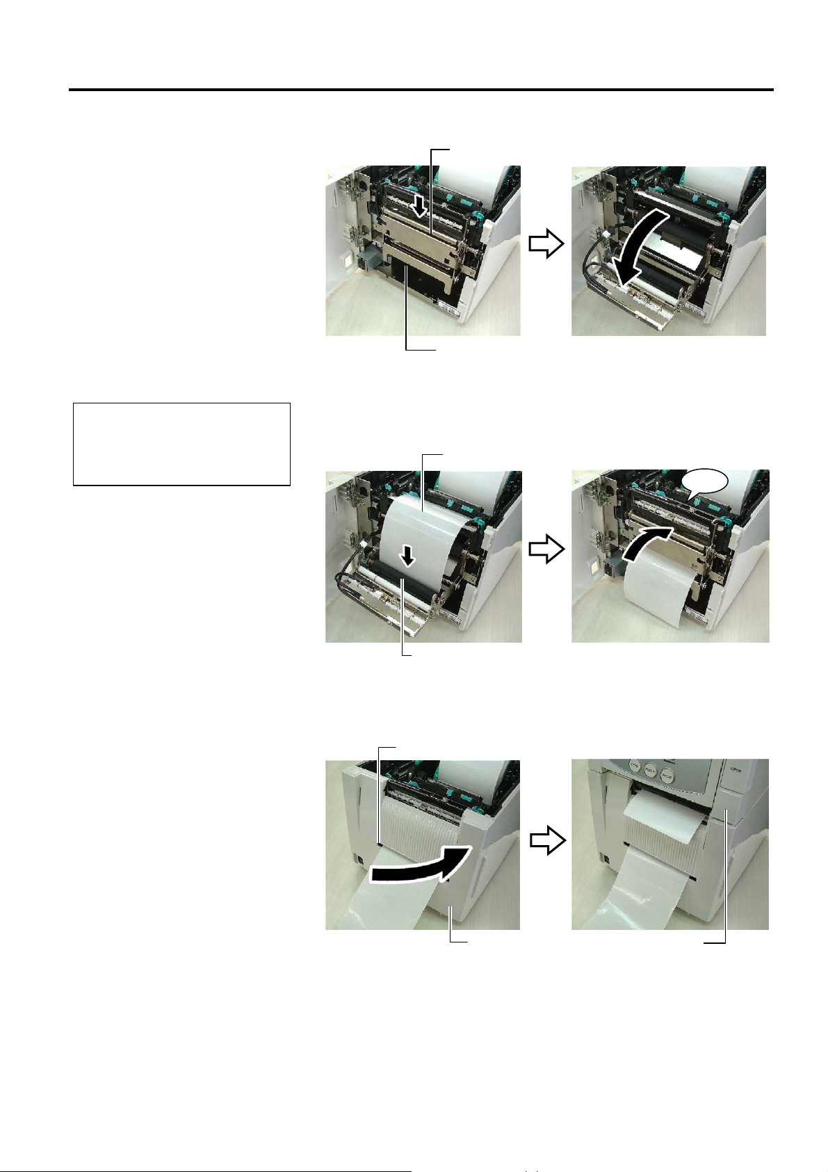
(2) Press down the Release Bar to open the Strip Unit.
Release Bar
Strip Unit
(3) Remove enough labels from the leading edge of the media to leave
300mm of backing paper free.
(4) Pass the backing paper through the opening under the Backing Paper
Feed Roller. Then, close the Strip Unit until it clicks.
Backing Paper
Click
Backing Paper Feed Roller
(5) Insert the leading edge of the backing paper into the slot of the Front
Cover.
(6) Close the Front Cover and the Top Cover.
Slot
Front Cover
Top Cover
E2- 9
2. PRINTER SETUP
)
ENGLISH VERSION EO1-33048
2.3 Loading the Media
(Cont.)
The cutter is sharp, so care
must be taken not to injure your
fingers when handling the
cutter.
1. When using a label stock, be
sure to cut the gaps. Cutting
labels will cause the glue to
stick to the cutter, which may
affect the cutter quality and
shorten the cutter life.
2. Use of tag paper which
thickness exceeds specified
value may affect the cutter
life. For the specification of
the media, refer to Section
7.1 Media.
1. Be sure to set both Head
Position Levers in the same
direction. Failure to do this
may cause blurred printing.
2. Do not leave the Head Position
Levers positioned at the middle.
When closing the Top Cover,
they block the Print Head
Positioning Shaft, and the Top
Cover cannot be closed.
WARNING!
CAUTION!
NOTES:
2.3 Loading the Media
Cut mode (Option
When the optional Cutter Module is fitted, the media is automatically cut.
Insert the leading edge of the media into the Media Outlet of the Cutter
Module.
Media
13. Change the print head pressure according to the thickness of the
media to be used, by using the Head Position Lever.
c
c
d
Head Position Lever
Head Position Lever
d
Print Head Positioning Shaft
Head Position Lever
c
d
Media type or thickness
Label or Thin media
If a clear print cannot be obtained,
d.
change the position to
Tag paper or Thick paper
If a clear print cannot be obtained,
c
change the position to
.
Move the levers
toward the front of
the printer.
Move the levers
toward the back of
the printer.
14. If the loaded media is direct thermal media (with a chemically
treated surface), the media loading procedure is now completed.
Close the Top Cover.
If the media is normal media, it is also necessary to load a ribbon.
Refer to Section 2.4 Loading the Ribbon.
E2-10
Head Position
Lever
2. PRINTER SETUP
ENGLISH VERSION EO1-33048
2.4 Loading the Ribbon
1. Do not touch any moving
parts. To reduce the risk of
fingers, jewellery, clothing,
etc., being drawn into the
moving parts, be sure to
load the ribbon once the
printer has stopped moving
completely.
2. The print head becomes hot
immediately after printing.
Allow it to cool before
loading the ribbon.
3. To avoid injury, be careful
not to trap your fingers
while opening or closing the
cover.
WARNING!
Be careful not touch the Print
Head Element when opening
the Top Cover. Failure to do
this may cause missing dots by
static electricity or other print
quality problems.
CAUTION!
2.4 Loading the Ribbon
There are two types of media available for printing on: these are thermal
transfer media (normal media) and direct thermal media (with a
chemically treated surface). DO NOT LOAD a ribbon when using a
direct thermal media.
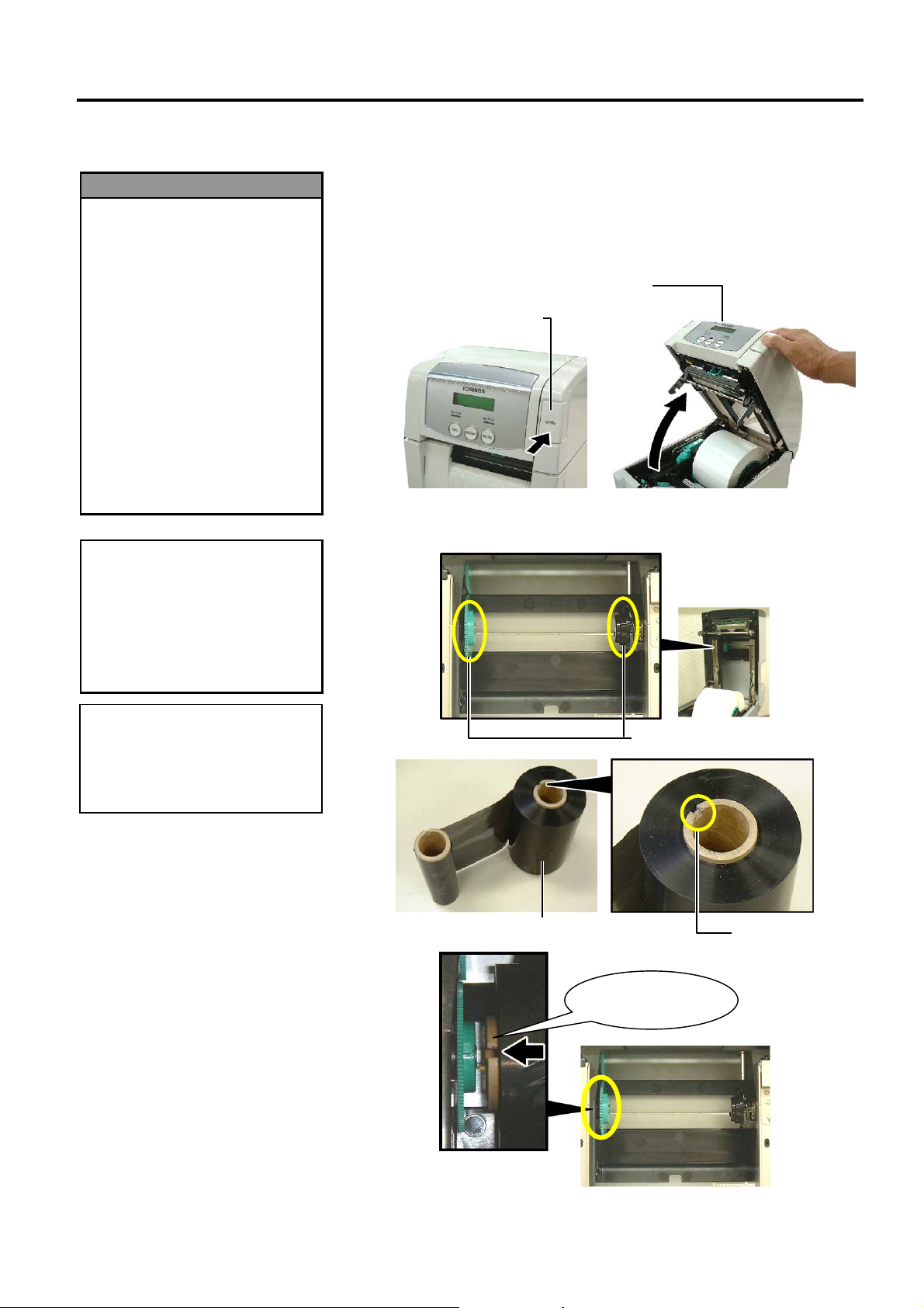
1. Press the Top Cover Release Button and gently open the Top Cover to
its fully open position supporting it with your hand.
Top Cover Release Button
2. Fit the core of the ribbon supply roll into the Ribbon Holders (Supply
side), aligning the notch of the ribbon core with the protrusion of the
Ribbon Stopper.
Top Cover
When replacing the ribbon, leave
the printer power on. Then, press
the
[RESTART] key to restart an
operation.
NOTE:
Ribbon Supply Roll
Ribbon Holder (Supply side)
Notch
Fit the protrusion
into the notch.
E2-11
2. PRINTER SETUP
ENGLISH VERSION EO1-33048
2.4 Loading the Ribbon
(Cont.)
2.4 Loading the Ribbon
°
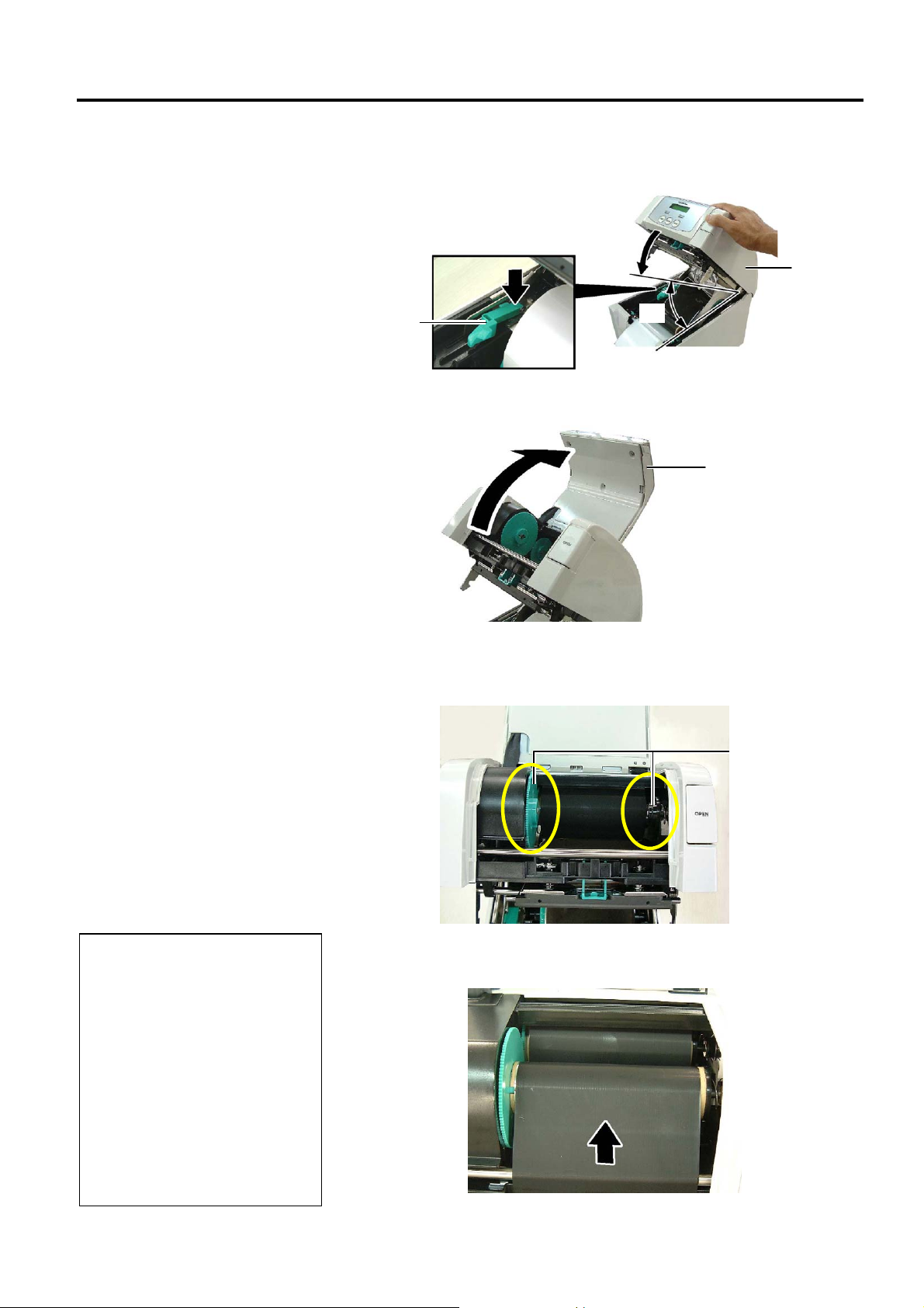
3. Lower the Top Cover to its 45
angle open position. While pushing
the Top Cover Stopper, raise the Top Cover again. This will fix the
Top Cover.
Top Cover
Top Cover
Stopper
45°
4. Open the Ribbon Cover.
Ribbon Cover
NOTES:
1. Be sure to remove any slack in
the ribbon when printing.
Printing with a wrinkled ribbon
will lower the print quality.
2. When a ribbon end is detected,
“RIBBON ERROR” message
will appear on the display and
the ERROR LED will illuminate.
3. When disposing of the ribbons,
please follow the local rules.
4. For the specification of
available ribbon, refer to
Section 7.2 Ribbon.
5. Fit the ribbon take-up core into the Ribbon Holder (Take-up side),
aligning the notch of the ribbon core with the protrusion of the Ribbon
Stopper.
Ribbon Holder
(Take-up side)
6. Turn the ribbon take-up core in the direction indicated by the arrow to
remove any slack.
E2-12

2. PRINTER SETUP
ENGLISH VERSION EO1-33048
2.4 Loading the Ribbon
(Cont.)
Be sure to close the Ribbon
Cover before closing the Top
Cover. It is dangerous to close
the Top Cover with the Ribbon
Cover opened, as the Ribbon
Cover slams shut.
WARNING!
7. Close the Ribbon Cover until it clicks.
8. Gently close the Top Cover until it clicks.
2.4 Loading the Ribbon
Ribbon Cover
Top Cover
E2-13
2. PRINTER SETUP
p
ENGLISH VERSION EO1-33048
2.5 Connecting the
Printer to Your Host
Computer
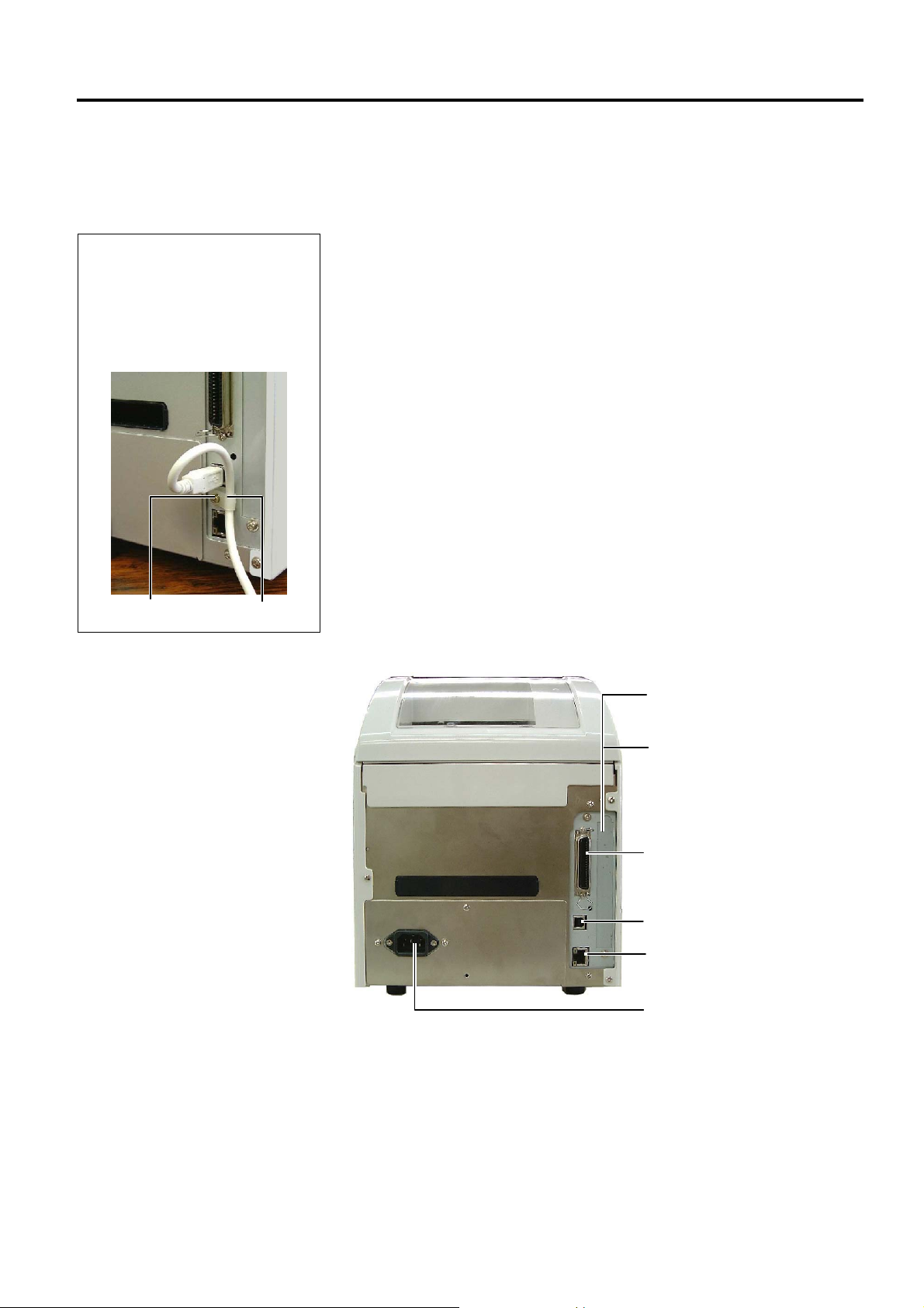
NOTE:
When using the USB interface, fix
the USB Interface Cable to the
rinter back with the supplied
Cable Clamp and the SMW-3x8
screw.
2.5 Connecting the Printer to Your Host Computer
The following paragraphs outline how to connect your host computer to
the printer, and will also show how to make cable connections to other
devices. Depending on the system configuration you use to print labels,
there are 5 possibilities for connecting the printer to your host computer.
These are:
• A parallel cable connection between the printer’s standard parallel
connector and your host computer’s parallel port (LPT).
• An Ethernet connection using the standard LAN board.
• A USB cable connection between the printer’s standard USB
connector and your host computer’s USB port. (Conforming to
USB 2.0 Full Speed)
• A serial cable connection between the printer’s optional RS-232C
serial connector and one of your host computer’s COM ports.
<Option>
• Wireless LAN using an optional Wireless LAN board. <Option>
SMW-3x8
Cable Clamp
For details of each interface, refer to APPENDIX 2.
After connecting the necessary interface cables, set an operating
environment of the printer. Refer to Section 2.7.2 Parameter Setting.
The diagram below shows all the possible cable connections to the
current version of the printer.
Serial Interface Connector
(Option)
Wireless LAN Interface Board
(Option)
Parallel Interface Connector
(Centronics)
USB Interface Connector
LAN Interface Connector
Power Inlet
E2-14
2. PRINTER SETUP
p
ENGLISH VERSION EO1-33048
2.6 Turning the Printer
ON
Use the power switch to turn the
rinter On/Off. Plugging or
unplugging the Power Cord to
turn the printer On/Off may
cause fire, an electric shock, or
damage to the printer.
1. If a message other than ON
LINE appears on the display or
the ERROR LED (Red) is
illuminated, go to Section 5.1,
Error Messages.
2. To turn OFF the printer power
turn the Power Switch to the
“{” side position.
CAUTION!
NOTES:
2.6 Turning the Printer ON
When the printer is connected to your host computer it is good practice to
turn the printer ON before turning on your host computer and turn OFF
your host computer before turning off the printer.
1. To turn ON the printer power, press the Power Switch as shown in the
diagram below. Note that ( | )
is the power ON side of the switch.
Power Switch
2. Check that the ON LINE message appears in the LCD Message
Display and that the ON LINE LED (Green) is illuminated.
E2-15
2. PRINTER SETUP
I
F
ENGLISH VERSION EO1-33048
2.7 Setting an Operating
Environment
1. System Mode menus can be
2. To enter each of the above
ON LINE
[PAUSE]
PAUSE
Hold down [RESTART] for 3 sec.
<1>RESET
[FEED]
<2>PARAMETER SET
[FEED]
<3>ADJUST SET
[FEED]
<4>DUMP MODE
[FEED]
<5>EXPAND MODE
[FEED]
selected with the [RESTART]
or [FEED] key.
System Mode menus, press the
[PAUSE] key when the menu is
displayed.
[RESTART]
[RESTART]
[RESTART]
[RESTART]
[RESTART]
NOTES:
2.7 Setting an Operating Environment
Depending on the settings of your host computer or an interface to be
used, it may be necessary to change the printer parameter settings.
Follow the procedures described below to change the printer parameter
settings in the System Mode to correspond to your environment.
ncorrect settings can cause the printer to function erroneously. If you
have any problems with the parameter settings, please contact your nearest
TOSHIBA TEC service representative.
or the settings this manual does not cover, please contact your nearest
TOSHIBA TEC service representative, or refer to the B-SA4T Series Key
Operation Specification stored in the CD-ROM.
NOTE:
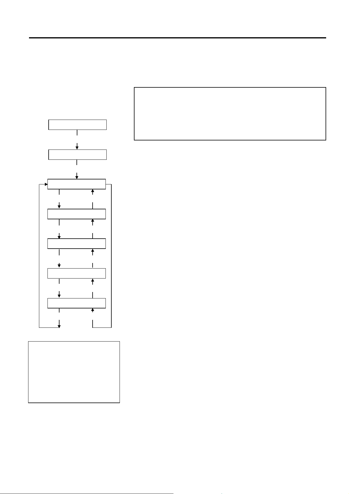
The System Mode consists of the following menus.
<1>RESET This menu is used to clear print data sent from a
PC and return the printer to an idle state.
Refer to Section 3.3 Reset.
<2>PARAMETER SET
This menu is used to set the printer parameters.
<3>ADJUST SET This menu is used to make a fine adjustment of a
print start position, cut position, etc.
Refer to Section 2.10 Position and Print Tone
Fine Adjustment.
<4>DUMP MODE This menu is used to print the data in the receive
buffer for debug.
<5>EXPAND MODE This menu is used to start the program for
BASIC mode.
Refer to the B-SA4T Series Key Operation
Specification stored in the CD-ROM.
E2-16
2. PRINTER SETUP
I
p
ENGLISH VERSION EO1-33048
2.7.1 How to Enter the
System Mode
ONLINE
B-SA4T V1.0
P
PAUSE
B-SA4T V1.0
R
2.7.2 Parameter Setting
<2>PARAMETER SET
P
2.7 Setting an Operating Environment
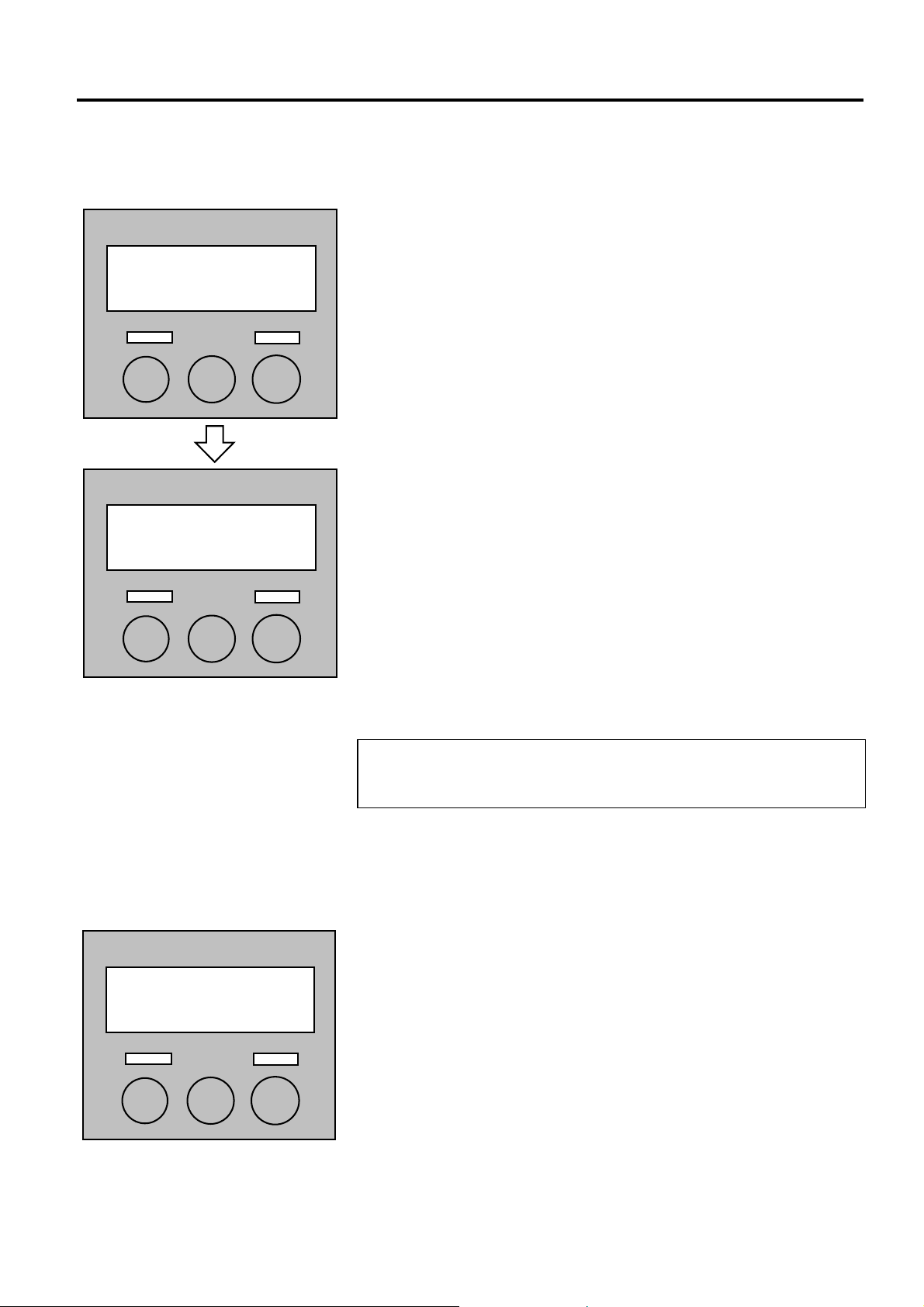
This section describes how to enter the System Mode.
1. Turn on the printer and confirm that “ONLINE” appears on the LCD
Message Display.
2. Press the [PAUSE] key to pause the printer.
3. Hold down the [RESTART] key for three seconds until “<1>RESET”
is displayed.
4. Press the [FEED] key, and “<2>PARAMETER SET” appears on the
LCD Message Display.
f the [PAUSE] key is pressed with “<1>RESET” being displayed, the
rinter will turn to an idle state and the message will change to “ONLINE”.
In this section, how to select a language and how to set the
communication parameters are described. When further information is
required, refer to the B-SA4T Series Key Operation Specification.
While “<2>PARAMETER SET” is displayed on the LCD Message
Display, press the [PAUSE] key to enter the Parameter Setting Mode.
NOTE:
E2-17
Loading...