


March, 2008
Part #46687-004

TOSHIBA
IMPORTANT NOTICE
The instructions contained in this manual are not intended to cover all of the details or variations in equipment, nor to provide for every possible contingency
to be met in connection with installation, operation, or maintenance. Should additional information be desired or should particular problems arise which are not covered sufficiently for the purchaser's purposes, the matter should be referred to the local Toshiba sales office.
The contents of this instruction manual shall not become a part of or modify any prior or existing agreement, commitment, or relationship. The sales contract contains the entire obligation of Toshiba International Corporation's Adjustable Speed Drive Division. The warranty contained in the contract between the parties is the sole warranty of Toshiba International Corporation's Adjustable Speed Drive Division and any statements contained herein do not create new warranties or modify the existing warranty.
Toshiba International Corporation reserves the right, without prior notice, to update information, make product changes, or to discontinue any product or service identified in this publication.
Any electrical or mechanical modification to this equipment, without prior written consent of Toshiba International Corporation, will void all warranties and may void UL listing.
AC ADJUSTABLE SPEED DRIVE
Please complete the Extended Warranty Card supplied with this inverter and return it by prepaid mail to Toshiba. This activates the extended warranty. If additional information or technical assistance is required, call Toshiba's marketing department toll free at (800) 231-1412 or write to: Toshiba International Corporation, 13131 W. Little York Road, Houston, TX 77041-9990.
For your records, complete the following information about the drive with which this manual was shipped.
H3 Model Number:
H3 Serial Number:
Date of Installation:
Inspected By:
Name of Application:
i

TOSHIBA
INTRODUCTION
Thank you for purchasing the H3 adjustable speed drive. This adjustable frequency solid-state AC drive features "True Torque Control" - Toshiba's 'vector algorithm' that enables motors to develop high starting torque and compensates for motor slip. The H3 also features a multi-lingual forty-character LCD display, RS232 port, dynamic braking transistor and ground fault, overload, and overcurent protection. These features, combined with built-in special control features such as PID, drooping, trim, and dancer control, make the H3 suitable for a wide variety of applications that require unparalleled motor control and
reliability.
It is the intent of this operation manual to provide a guide for safely installing, operating, and maintaining the drive. This operation manual contains a section of general safety instructions and is marked
throughout with warning symbols. Read this operation manual thoroughly before installing and operating this electrical equipment.
All safety warnings must be followed to ensure personal safety.
Follow all precautions to attain proper equipment performance and longevity.
We hope that you find this operation manual informative and easy to use. For assistance with your H3, for information on our free drive application school, or for information on Toshiba's complete line of motors, adjustable speed drives, switchgear, instrumentation, uninterruptable power supplies, PLCs, and motor control products, please call toll free (800) 231-1412 or write to our plant at: Toshiba International Corporation, 13131 W. Little York Road, Houston, TX 77041-9990.
Again, thank you for your purchase of this product.
COPYRIGHT © [MARCH, 2008] TOSHIBA INTERNATIONAL CORPORATION
ii
TOSHIBA
GENERAL SAFETY INSTRUCTIONS
Warnings in this manual appear in either of two ways:
1)Danger warnings - The danger warning symbol is an exclamation mark enclosed in a triangle which precedes the 3/16" high letters spelling the word "DANGER". The Danger warning symbol is used to indicate situations, locations, and conditions that can cause serious injury or death:
 DANGER
2)Caution warnings - The caution warning symbol is an exclamation mark enclosed in a triangle which precedes the 3/16" high letters spelling the word "CAUTION". The Caution warning symbol is used to indicate situations and conditions that can cause operator injury and/or equipment damage:
 CAUTION
Other warning symbols may appear along with the Danger and Caution symbol and are used to specify special hazards. These warnings describe particular areas where special care and/or procedures are required in order to prevent serious injury and possible death:
1)Electrical warnings - The electrical warning symbol is a lighting bolt mark enclosed in a triangle. The Electrical warning symbol is used to indicate high voltage locations and conditions that may cause serious injury or death if the proper precautions are not observed:
2)Explosion warnings - The explosion warning symbol is an explosion mark enclosed in a triangle. The Explosion warning symbol is used to indicate locations and conditions where molten, exploding parts may cause serious injury or death if the proper precautions are not observed:
For the purpose of this manual and product labels, a Qualified Person is one who is familiar with the installation, construction, operation and maintenance of the equipment and the hazards involved. This person must:
1)Carefully read the entire operation manual.
2)Be trained and authorized to safely energize, de-energize, clear faults, ground, lockout and tag circuits and equipment in accordance with established safety practices.
3)Be trained in the proper care and use of protective equipment such as safety shoes, rubber gloves, hard hats, safety glasses, face shields, flash clothing, etc. in accordance with established safety practices.
4)Be trained in rendering first aid.
iii

|
TOSHIBA |
|
|
|
|
|
CONTENTS |
|
|
|
PAGE |
Disclaimer ............................................................................................... |
i |
|
Introduction .............................................................................................. |
ii |
|
General Safety Instructions ..................................................................... |
iii |
|
Contents ............................................................................................ |
iv-vi |
|
Section 1 |
Inspection/Storage/Disposal |
|
Inspection of the New Unit......................................................................... |
1-1 |
|
Storage ............................................................................................. |
1-1 |
|
Disposal ............................................................................................. |
1-1 |
|
Section 2 Installation and Operation |
|
|
Installation Safety Precautions .................................................................. |
2-1 |
|
Operating Safety Precautions.................................................................... |
2-2 |
|
Confirmation of Wiring ............................................................................... |
2-3 |
|
Start-up and Test ....................................................................................... |
2-4 |
|
Maintenance ............................................................................................. |
2-4 |
|
Section 3 |
Specifications |
|
230 Volt NEMA Type 1 Chassis Ratings ................................................... |
3-1 |
|
460 Volt NEMA Type 1 Chassis Ratings ................................................... |
3-1 |
|
Standard Specifications ............................................................................. |
3-2 |
|
Section 4 |
Wiring |
|
Standard Connection Diagrams ................................................................ |
4-1 |
|
Selection of Main Circuit Wiring Equipment and |
|
|
Standard Cable Sizes ................................................................................ |
4-3 |
|
Grounding ............................................................................................. |
4-5 |
|
Application Notes: Motor Selection............................................................ |
4-5 |
|
Connection Examples |
|
|
|
Potentiometer Operation ................................................................. |
4-6 |
|
4-20 mA Reference Operation ........................................................ |
4-7 |
|
Keypad Reference and Remote Stop/Start .................................... |
4-8 |
|
RS232 Port ..................................................................................... |
4-9 |
|
0-10 Volt Reference Operation ....................................................... |
4-9 |
iv

|
TOSHIBA |
|
|
|
|
|
CONTENTS (cont'd) |
|
|
|
PAGE |
Section 5 Jumper and Terminal Connections |
|
|
Terminal Strip Board .................................................................................. |
5-1 |
|
Control Board ............................................................................................ |
5-2 |
|
Terminal Connections and Functions ........................................................ |
5-3 |
|
Section 6 |
Operating Panel |
|
Panel Layout ............................................................................................. |
6-1 |
|
Keys and Functions ................................................................................... |
6-2 |
|
Section 7 |
Keypad Functions |
|
Local Mode ............................................................................................. |
7-1 |
|
|
Forward/Rerverse Change ............................................................. |
7-1 |
|
Jog ............................................................................................. |
7-1 |
|
Coast Stop ...................................................................................... |
7-2 |
Programming Mode ................................................................................... |
7-2 |
|
Remote Mode ............................................................................................ |
7-2 |
|
|
ESTOP............................................................................................ |
7-2 |
Other: Language Selection ........................................................................ |
7-2 |
|
Monitor Mode............................................................................................. |
7-3 |
|
|
Monitoring "RR" Input Special Function .......................................... |
7-4 |
|
Monitoring Pattern Run ................................................................... |
7-4 |
Section 8 |
Programming Charts |
|
Fundamental Parameters #1 ..................................................................... |
8-1 |
|
Fundamental Parameters #2 ..................................................................... |
8-2 |
|
Panel Control Parameters ......................................................................... |
8-3 |
|
Special Control Parameters ....................................................................... |
8-4 |
|
Terminal Selection Parameters ................................................................. |
8-5 |
|
Frequency Setting Parameters .................................................................. |
8-8 |
|
Protection Parameters .............................................................................. |
8-13 |
|
Pattern Run Control Parameters .............................................................. |
8-16 |
|
Feedback Parameters .............................................................................. |
8-22 |
|
Communication Setting Parameters ......................................................... |
8-24 |
|
Industrial Application Parameters (Pump) ................................................ |
8-26 |
|
Industrial Application Parameters (Fan) ................................................... |
8-26 |
|
Industrial Application Parameters (Conveyor) .......................................... |
8-26 |
|
Industrial Application Parameters (Hoist) ................................................. |
8-26 |
|
Industrial Application Parameters (Textiles) ............................................. |
8-26 |
|
v

TOSHIBA
CONTENTS (cont'd)
|
|
PAGE |
Section 8 Programming Charts (cont'd) |
|
|
Industrial Application Parameters (Machine Tools) |
..................................8-26 |
|
AM/FM Terminal Adjustment Parameters................................................. |
8-27 |
|
Utility Parameters ..................................................................................... |
8-28 |
|
Motor Parameters ..................................................................................... |
8-32 |
|
Parameter Tree ........................................................................................ |
8-33 |
|
Section 9 |
Programming |
|
Groups ............................................................................................. |
9-1 |
|
Blinding ............................................................................................. |
9-2 |
|
Search Function ........................................................................................ |
9-2 |
|
Parameter Explanations ............................................................................ |
9-3 |
|
Programming Examples ........................................................................... |
9-30 |
|
Section 10 |
Service |
|
Requesting After Sales Service ................................................................ |
10-1 |
|
Parts Service Life ..................................................................................... |
10-2 |
|
Troubleshooting ........................................................................................ |
10-3 |
|
|
How to Clear a Fault ...................................................................... |
10-3 |
|
Drive Fault Displays and Explanations .......................................... |
10-3 |
|
Drive Warning Displays and Explanations ..................................... |
10-7 |
Section 11 |
Dimensions/Weights |
|
Basic Dimensions ..................................................................................... |
11-1 |
|
Shipping Weights...................................................................................... |
11-3 |
|
Drive Options ............................................................................................ |
11-4 |
|
Keypad Cutout .......................................................................................... |
11-5 |
|
Section 12 |
Index ............................................................................................ |
12-1 |
vi

TOSHIBA
SECTION 1: Inspection/Storage/Disposal
Inspection of the New Unit
Upon receipt of the H3, a careful inspection for shipping damage should be made. After uncrating:
1)Check the unit for loose, broken, bent or otherwise damaged parts due to shipping.
2)Check to see that the rated capacity and the model number specified on the nameplate conform to the order specifications.
Storage
1)Store in a well ventilated location and preferably in the original carton if the inverter will not be used immediately after purchase.
2)Avoid storage in locations with extreme temperatures, high humidity, dust, or metal particles.
Disposal
Please contact your state environmental agency for details on disposal of electrical components and packaging in your particular area. Never dispose of electrical components via incineration.
Inspection
Precautions
Specifications
Wiring
Jumpers
Panel
Keypad
Parameters
Programming
Service
Dimensions
Index
1 - 1
TOSHIBA
SECTION 2: Installation and Operation
Installation Safety Precautions |
CAUTION |
1)Install in a secure and upright position in a well ventilated location that is out of direct sunlight. The ambient temperature should be between -10° C and 40° C.
2)Allow a clearance space of 8 inches (20 cm) for the top and bottom and 2 inches
(5 cm) on both sides. For models 2010-2270 and models 4015-4500, the top and bottom clearance can be reduced to 4 inches (10 cm). This space will insure adequate ventilation. Do not obstruct any of the ventilation openings.
3)Avoid installation in areas where vibration, heat, humidity, dust, steel particles, or sources of electrical noise are present.
4)Adequate working space should be provided for adjustment, inspection and maintenance.
5)Adequate lighting should be available for troubleshooting and maintenance.
6)A noncombustible insulating floor or mat should be provided in the area immediately surrounding the electrical system where maintenance is required.
7) |
Always ground the unit to prevent electrical shock and to help |
|
reduce electrical noise. A separate ground cable should be run |
|
inside the conduit with the input, output, and control power |
|
cables (See Grounding page 4-5). |
THE METAL OF CONDUIT IS NOT AN ACCEPTABLE GROUND.
8)Use lockout/tagout procedures before connecting three phase power of the correct voltage to input terminals L1, L2, L3 (R, S, T) and connect three phase power from output terminals T1, T2, T3 (U, V, W) to a motor of the correct voltage and type for the application. Size the conductors in accordance with Selection of Main Circuit Wiring Equipment and Standard Cable Sizes Page 4-3.
9)If conductors of a smaller than recommended size are used in parallel to share current then the conductors should be kept together in sets i.e. U1, V1, W1 in one conduit and U2, V2, W2 in another. National and local electrical codes should be checked for possible cable derating factors if more than three power conductors are run in the same conduit.
10)Install a molded case circuit breaker (MCCB) between the power source and the inverter. Size the MCCB to clear the available fault current of the power source.
11)Use separate metal conduits for routing the input power, output power, and control circuits.
12)Installation of drive systems should conform to the National Electrical Code, regulations of the Occupational Safety and Health Administration, all national, regional or industry codes and standards.
13)If the factory provided enclosure is removed from the drive, then it must be provided with an alternate enclosure before operating. The alternate enclosure should be a minimum of NEMA 1.
2 - 1
TOSHIBA
Installation Safety Precautions (cont'd) |
CAUTION |
14)Do not connect control circuit terminal block return connections marked CC to inverter earth ground terminals marked GND(E). See Standard Connection Diagrams page 4-1 and Terminal Connections and Functions page 5-3.
15)If a secondary Magnetic Contactor (MC) is used between the inverter output and the load, it should be interlocked so the ST-CC terminals are disconnected before the output contactor is opened. If the output contactor is used for bypass operation, it must also be interlocked so that commercial power is never applied to the inverter output terminals (U,V,W).
16)Power factor improvement capacitors or surge absorbers must not be installed on the inverter's output.
17)Only qualified personnel should install this equipment.
Operating Safety Precautions |
CAUTION |
|
1)Do not power up the inverter until this entire operation manual is reviewed.
2)The input voltage must be within +/-10% of the specified input voltage. Voltages outside of this permissible tolerance range may cause internal protection devices to turn on or can cause damage to the unit. Also, the input frequency should be within +/-2 Hz of the specified input frequency.
3)Do not use this inverter with a motor whose rated input is greater than the rated inverter output.
4)This inverter is designed to operate NEMA B motors. Consult the factory before using the inverter for special applications such as an explosion proof motor or one with a repetitive type piston load.
5) DANGER
Do not touch any internal part with power applied to the inverter; first remove
the power supply from the drive and wait until charge LED (see page 5-1 for location) is no longer illuminated. Charged capacitors can present a hazard even if source power is removed.
6) |
DO NOT OPERATE THIS UNIT WITH ITS CABINET DOOR OPEN. |
7)Do not apply commercial power to the output terminals T1 (U), T2 (V), or T3
(W) even if the inverter source power is off. Disconnect the inverter from the motor before megging or applying bypass voltage to the motor.
Inspection
Precautions
Specifications
Wiring
Jumpers
Panel
Keypad
Parameters
Programming
Service
Dimensions
Index
2 - 2

|
TOSHIBA |
Operating Safety Precautions (cont'd) |
CAUTION |
|
8)Interface problems can occur when this drive is used in conjunction with some types of process controllers. Signal isolation may be required to
prevent controller and/or drive malfunction (contact Toshiba or the process controller manufacturer for additional information about compatibility and signal isolation).
9)Do not open and then re-close a secondary magnetic contactor (MC) between the drive and the load unless the drive is OFF (output frequency has
dropped to zero) and the motor is not rotating. Abrupt re-application of the load while drive is on or while motor is rotating can cause drive damage.
10)Use caution when setting output frequency. Overspeeding a motor can decrease its torque-developing ability and can result in damage to the motor and/or driven equipment.
11)Use caution when setting the acceleration and deceleration time. Unnecessarily short times can cause tripping of the drive and mechanical stress to loads.
12)Only qualified personnel should have access to the adjustments and
operation of this equipment. They should be familiar with the drive operating instructions and with the machinery being driven.
13)Only properly trained and qualified personnel should be allowed to service this equipment. See page iii.
14)Follow all warnings and precautions. Do not exceed equipment ratings.
Confirmation of Wiring  CAUTION
Make the following final checks before applying power to the unit:
1)Confirm that source power is connected to terminals L1, L2, L3 (R, S, T).
Connection of incoming source power to any other terminals will damage the drive.
2)The 3-phase source power should be within the correct voltage and frequency tolerances.
3)The motor leads must be connected to terminals T1, T2, T3 (U, V, W).
4)Make sure there are no short circuits or inadvertent grounds and tighten any loose connector terminal screws.
2 - 3
TOSHIBA
Start-Up and Test |
CAUTION |
Prior to releasing an electrical drive system for regular operation after installation, the system should be given a start-up test by qualified personnel. This assures correct operation of the equipment for reasons of reliable and safe performance. It is important to make arrangements for such a check and that time is allowed for it.
When power is applied for the first time, the drive's parameters are set to the values
listed as "FACTORY SETTING" in the charts starting on page 8-1. If these settings are not optimal for the application, program the desired settings before initiating a run. The
drive can be operated with no motor connected. Operation with no motor connected or use with a small trial motor is recommended for initial adjustment or for learning to adjust and operate the drive.
Maintenance  CAUTION
1)Use lockout/tagout procedures in accordance with local electrical codes before performing any drive maintenance.
2)Periodically check the operating drive for cleanliness.
3)Do not use liquid cleaning agents.
4)Keep the heatsink free of dust and debris.
5) |
Periodically check electrical connections for tightness (with power off, |
|
locked out, and with charge LED out (see page 5-1 for location)). |
Inspection
Precautions
Specifications
Wiring
Jumpers
Panel
Keypad
Parameters
Programming
Service
Dimensions
Index
2 - 4

TOSHIBA
SECTION 3: Specifications
230 Volt NEMA Type 1 Chassis Standard Ratings
|
H3 |
|
|
|
|
STANDARD RATINGS |
|
|
||
MODEL |
|
NOTES |
below)(see |
RATED |
MOTOR |
(AMPS) |
OUTPUT |
OVERLOAD |
3-PHASE |
POWER |
|
|
|
|
OUTPUT |
MAIN CIRCUIT |
INPUT |
||||
|
|
|
|
KVA |
HP(KW) |
CURRENT |
VOLTAGE |
CURRENT |
INPUT POWER |
CONTROL |
|
|
|
|
|
|
|
|
|
|
|
2035 |
|
(1) |
|
3.5 |
3/2.2 |
10.6 |
200-230V |
120% FOR |
200V/50Hz or |
NO EXTERNAL |
2055 |
|
(1) |
|
5.5 |
5/3.7 |
17 |
3-PHASE |
60 SEC. |
200-230V/60Hz |
CONTROL |
2080 |
|
(1) |
|
8 |
7.5/5.5 |
24.3 |
MAX VOLTAGE |
110% |
VOLTAGE +/- 10% |
POWER SOURCE |
2110 |
|
(1) |
|
11 |
10/7.5 |
33 |
|
CONTINUOUS |
FREQ. +/- 2Hz |
REQUIRED |
2160 |
|
(1) |
|
16 |
15/11 |
46 |
|
|
|
|
2220 |
|
(1) |
|
22 |
20/15 |
60 |
|
|
|
|
2270 |
|
(1) |
|
27 |
25/18 |
75 |
|
|
|
|
2330 |
|
(1) |
|
33 |
30/23 |
89 |
|
|
|
|
NOTES:
1) NEMA Type1 UL/CUL listing
460 Volt NEMA Type 1 Chassis Standard Ratings
H3 |
|
|
|
|
|
STANDARD RATINGS |
|
|
||
MODEL |
|
NOTES |
below)(see |
RATED |
MOTOR |
(AMPS) |
OUTPUT |
OVERLOAD |
3-PHASE |
POWER |
|
|
|
|
OUTPUT |
MAIN CIRCUIT |
INPUT |
||||
|
|
|
|
KVA |
HP(KW) |
CURRENT |
VOLTAGE |
CURRENT |
INPUT POWER |
CONTROL |
|
|
|
|
|
|
|
|
|
|
|
4055 |
|
(1) |
|
5.5 |
5/3.7 |
7.6 |
380-460V |
120% FOR |
380V/50Hz or |
NO EXTERNAL |
4080 |
|
(1) |
|
8 |
7.5/5.5 |
11 |
3-PHASE |
60 SEC. |
400-460V/60Hz |
CONTROL |
4110 |
|
(1) |
|
11 |
10/7.5 |
15 |
MAX VOLTAGE |
110% |
VOLTAGE +/- 10% |
POWER SOURCE |
4160 |
|
(1) |
|
16 |
15/11 |
22 |
|
CONTINUOUS |
FREQ. +/- 2Hz |
REQUIRED |
4220 |
|
(1) |
|
22 |
20/15 |
28 |
|
|
|
|
4270 |
|
(1) |
|
27 |
25/18.5 |
34 |
|
|
|
|
4330 |
|
(1) |
|
33 |
30/22 |
40 |
|
|
|
|
4400 |
|
(1) |
|
40 |
40/30 |
56 |
|
|
|
|
4500 |
|
(2) |
|
50 |
50/37 |
65 |
|
|
|
|
4600 |
|
(2) |
|
60 |
60/45 |
82 |
|
|
|
|
4750 |
|
(1) |
|
75 |
75/55 |
104 |
|
|
|
|
410K |
|
(1) |
|
100 |
100/75 |
124 |
|
|
|
|
412K |
|
(1) |
|
125 |
125/90 |
156 |
|
|
|
|
415K |
|
(1) |
|
150 |
150/110 |
180 |
|
|
|
|
420K |
|
(1) |
|
200 |
200/150 |
240 |
|
|
|
|
425K |
|
(1) |
|
250 |
250/185 |
300 |
|
|
|
|
430K |
|
(1) |
|
300 |
300/220 |
360 |
|
|
|
|
NOTES:
1) NEMA Type 1 UL/CUL listing.
3 - 1

TOSHIBA
Standard Specifications
|
|
|
ITEM |
STANDARD SPECIFICATIONS |
|
|
|
|
|
Principal |
Control System |
Sinusoidal PWM control |
||
Control |
|
Output voltage regulation |
Same as power line. |
|
Specifications |
|
Output frequency |
0.01 to 400 Hz (0.1 to 80Hz default setting)*. 800 Hz operation |
|
|
|
|
|
possible. |
|
|
|
Frequency setting |
0.1Hz from operating panel input (60Hz base), 0.01Hz from analog |
|
|
|
|
input (60Hz base, 12-bit/0 to 10Vdc), 0.01Hz from computer interface |
|
|
|
|
(60Hz base) |
|
|
|
|
|
|
|
|
Frequency accuracy |
Analog input: ±0.2% of the maximum output frequency (25°C±10°C), |
|
|
|
|
Digital input: ±0.01% (25°C±10°C) |
|
|
|
Voltage/frequency |
Constant V/f, variable torque, automatic torque boost, True Torque |
|
|
|
characteristics |
Control and automatic energy-saving control/maximum voltage |
|
|
|
|
frequency adjustment (25 to 400Hz), torque boost adjustment |
|
|
|
|
(0 to 30%), start-up frequency adjustment (0 to 10Hz). |
|
|
|
PWM carrier frequency |
Adjustable between 0.5 and 10kHz |
|
|
|
Transistor type |
Insulated gate bipolar (IGBT) |
|
|
|
Output voltage regulation |
Drive can be programmed to fix max. output volts, let max. float with |
|
|
|
|
input voltage, or set max. to input voltage sensed at power-up. |
|
|
|
Dynamic braking |
Feature not available in H3 drives above 30 HP. |
Frequency |
Input signals |
3k ohms potentiometer (1k ohm to 10k ohm-rated potentiometer |
||
|
|
|
|
can be connected). 0 to 10Vdc (Zin=33k ohm), ±10 Vdc (Zin=67k |
|
|
|
|
ohm), +/-5 Vdc (Zin=34k ohm), 4 to 20mAdc (Zin=500 ohm) |
|
|
|
Set point control (PID) |
Proportional gain, integral gain, anti-hunting gain, lag time constant, |
|
|
|
|
and PID error limit adjustments. |
Operating |
Accel/decel time |
0.1 to 6000 secs, accel/decel time 1 or 2 selection, accel/decel |
||
functions |
|
pattern selection |
||
|
|
|
Forward or reverse run |
Forward run when F-CC closed (default); reverse run when R-CC |
|
|
|
|
closed (default); reverse run when both closed (default); coast-stop |
|
|
|
|
when ST-CC opened (default); emergency coast stop by a |
|
|
|
|
command from operating panel or terminal block; 3-wire control and |
|
|
|
|
motorized speed pot programmable functions. |
|
|
|
Jogging run |
Jog run from panel with JOG mode selection. Terminal |
|
|
|
|
block operation possible with parameter settings. |
|
|
|
Multispeed run |
Set frequency plus 15 preset speeds possible with combinations of |
|
|
|
|
CC, SS1, SS2, SS3, and SS4 (default functions). |
|
|
|
Retry |
When a protective function is activated, the system checks main |
|
|
|
|
circuit devices, and attempts to restart. Settable to a maximum |
|
|
|
|
of 10 times; wait time adjustment (0 to 10 secs) |
|
|
|
Soft stall |
Automatic load reduction during overload (Default setting: OFF). |
|
|
|
Automatic restart |
A coasting motor can be smoothly restarted (Default setting: OFF). |
|
|
|
Pattern Run |
4 groups of 8 patterns each can be set to the 15 preset speed values. |
|
|
|
|
A maximum of 32 different patterns can be run; terminal block |
|
|
|
|
control/repetitive run possible. |
|
|
|
DC injection braking |
Braking starting frequency adjustment (0 to 120Hz), braking current |
|
|
|
|
adjustment (0 to 100%), braking time adjustment (0 to 10secs), |
|
|
|
|
emergency stop braking function, motor shaft stationary control. |
|
|
|
Upper/Lower limit |
Limits the frequency between the set values (0 to max. frequency). |
|
|
|
|
Can be indicated via output contact closure. |
|
|
|
Frequency jump |
3 jump frequency settings (each with unique band settings) |
|
|
|
Edit function |
Easy access user group containing all changed parameters |
|
|
|
Blind function |
Select to display needed parameter groups and parameters |
|
|
|
User-defined defaults |
User's parameter values can be saved into a default library. User |
|
|
|
|
can then default drive to Toshiba's values or to the user's own. |
|
|
|
|
|
*Consult the factory for applications above 80 Hz.
Inspection
Precautions
Specifications
Wiring
Jumpers
Panel
Keypad
Parameters
Programming
Service
Dimensions
Index
3 - 2

TOSHIBA
Standard Specifications (cont'd)
|
ITEM |
STANDARD SPECIFICATIONS |
|
|
|
Display |
Interface |
2-line backlit display LCD 20 characters per line |
|
Fault display |
Overcurrent, overvoltage, heatsink overheat, load-side short-circuit, |
|
|
load-side ground fault, inverter overload, stator overcurrent during |
|
|
start-up, load-side overcurrent during start-up, EEPROM error, RAM |
|
|
error, ROM error, communication error, (dynamic braking unit |
|
|
overcurrent/overload), (emergency stop), (undervoltage), (low |
|
|
current), (overtorque), (open output phase), (motor overload). Items |
|
|
in parenthesis can be selected or deselected. |
|
Monitor functions |
Terminal input/output status, forward/reverse, frequency setting |
|
|
value, output frequency, output current, output voltage, input power, |
|
|
output power, torque current, cumulative run time, past faults, |
|
|
excitation current, DBR overload ratio, inverter overload ratio, motor |
|
|
overload ratio, PID feedback value, DC voltage. |
|
Selectable units display |
Can scale frequency display. |
|
|
Selection of display of current in amps or %, voltage in V or %. |
|
LED charge indicator |
Indicates that the main circuit capacitors are charged |
|
LED local/remote |
Mounted in LOCAL/REMOTE key. Indicates local (keypad) or |
|
indicator |
remote (terminal) control |
Inverter/Motor |
Protective functions |
Soft-stall, current limit, overcurrent, overvoltage, short-circuit at load, |
|
|
load-side ground fault, undervoltage, momentary power failure, |
|
|
regeneration power ride-through, electronic thermal overload |
|
|
protection, main circuit overcurrent at start-up, load-side overcurrent |
|
|
during start-up, DBR resistor overcurrent/overload, heatsink over |
|
|
heat, emergency stop, open output phase. |
|
Electronic thermal |
Drive's motor overload protection for motor can be adjusted for motor |
|
characteristics |
rated amperage. Motor overload has adjustable speed sensitivity. |
|
|
Soft stall on/off. Motor 150% time programmable. |
|
Reset |
Fault reset via keypad, remote contact closure, or programming drive |
|
|
retry. Cycling power also resets fault (fault display can be maintained) |
|
Regeneration power |
Some H3 ratings can use regen energy from motor to maintain |
|
ride-through control |
operation during brown-outs. |
Output signals |
Fault detection signal |
NC/NO form C contact (250VDC, 2A) |
|
Low speed/reach signals |
Dry contacts (250VDC, 2A) |
|
Upper limit/lower limit |
Dry contacts (250VDC, 2A) |
|
Programmable meter |
Pre-compensation reference frequency, post-compensation output |
|
output signals |
frequency, frequency setting value, output current, DC voltage, |
|
|
output voltage, torque current, excitation current, PID feedback value, |
|
|
motor/inverter/DBR overload ratio, input/output power. |
|
Pulse-train frequency |
Open collector output (max. 24 Vdc, 50mA) |
|
Communication functions |
RS232C equipped as standard ( connector: modular 6P), RS485, |
|
|
TOSLINE-F10, TOSLINE-F20, RIO, DN, and MB+ are options. |
Enclosure |
Type |
NEMA Type 1 |
|
Cooling method |
Forced air cooling . Fan can be automatically stopped when not |
|
|
necessary for extended fan life. |
|
Color |
Sherwin Williams Precision Tan #F63H12 |
|
Service environment |
Indoor. Consult factory for elevations above 1000m (requires derate). |
|
|
For example, at 2000m, derate drive FLA by 11%. |
|
|
Must not be exposed to direct sunlight, corrosive and/or explosive |
|
|
gases or mists, fibers and dusts. |
|
Ambient temperature |
From -10°C to 40°C (14°F to 104°F). |
|
Relative humidity |
20 to 95% maximum (non-condensating) |
|
Vibration |
5.9 m/s 2(0.5G) maximum (10 to 55Hz) |
|
Climatic class |
3K3 |
|
Polution degree |
2 |
|
IP rating |
2X |
3 - 3

TOSHIBA
SECTION 4: Wiring
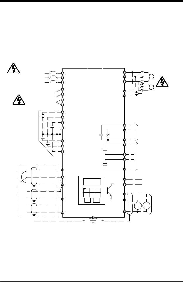
Standard Connection Diagrams
TOSVERT-130H3
STANDARD CONNECTION
MODEL 2035 TO 2330
MODEL 4055 TO 4330
|
|
DBR |
|
|
|
|
|
MCCB |
|
PA PB |
T1(U) |
|
|
|
|
INPUT POWER SUPPLY |
L1(R) |
|
|
|
|
||
L2(S) |
|
T2(V) |
|
|
M |
|
|
(see notes 1 and 2 below) |
|
|
|
|
|||
L3(T) |
|
T3(W) |
|
|
|
|
|
|
|
|
|
|
|
||
|
RES |
(see note 3 below) S4 |
|
|
M |
|
|
|
F |
|
|
|
|
||
|
|
CC |
|
|
|
|
|
|
R |
|
|
|
|
|
|
PROGRAMMABLE |
|
FLA |
|
|
|
|
|
SIGNAL INPUT |
ST |
|
FLB |
PROGRAMMABLE |
|||
|
|
|
|
OUTPUT CONTACTS |
|||
|
|
|
FLC |
250V, 2A MAX |
|||
|
S1 |
|
|
|
|
|
|
|
|
R/CH-A |
|
|
|
|
|
|
S2 |
|
|
|
|
|
|
|
|
|
|
|
|
|
|
|
S3 |
|
R/CH-C |
PROGRAMMABLE |
|||
PROGRAMMABLE |
|
|
LOW-A |
OUTPUT CONTACTS |
|||
|
|
250V, 2A MAX |
|||||
ANALOG INPUT |
|
|
|
||||
|
|
|
|
|
|
|
|
Potentiometer |
PP |
DIGITAL |
LOW-C |
|
|
|
|
|
|
|
|
|
|
||
|
RR |
OPERATION PANEL |
|
|
|
|
|
|
|
P24 |
|
50mA MAX |
|||
|
|
|
|
||||
|
CC |
|
FP |
|
PULSE OUTPUT |
||
- |
|
|
FM |
|
|
|
|
AUTO |
|
|
|
|
|
|
|
REF. |
IV |
|
AM |
|
|
|
PROGRAMMABLE |
+ |
|
+ |
|
+ |
|||
|
|
|
|
SIGNAL OUTPUT |
|||
- |
|
|
AM |
|
FM |
|
|
|
|
|
|
|
0-1mA or 4-20mA |
||
AUTO |
|
|
CC |
|
|
|
|
|
|
|
|
|
|
||
REF. |
RX |
|
|
|
|
|
|
+ |
GND(E) |
|
|
|
|
|
|
|
|
|
|
|
|
||
NOTES:
1.) For drive models 2035 through 2330 use input power supply of 200VAC, 50Hz or 200-230VAC, 60Hz.
2.) For drive models 4055 through 4330 use input power supply of 380VAC, 50Hz or 400-460VAC, 60Hz.
3.) As an example, the "S4" terminal is shown above as an EMERGENCY OFF input. See Section 8 for information on how to program the drive for this and other functions.
Inspection
Precautions
Specifications
Wiring
Jumpers
Panel
Keypad
Parameters
Programming
Service
Dimensions
Index
4 - 1
TOSHIBA
Standard Connection Diagrams (cont'd)
TOSVERT-130H3
STANDARD CONNECTION
MODEL 4400 TO 430K
MCCB
INPUT POWER SUPPLY (set by input power selection)
INPUT POWER SELECTION
415/460V-50/60Hz
400/440V-50/60Hz 380V-50Hz
PROGRAMMABLE
SIGNAL INPUT
PROGRAMMABLE
ANALOG INPUT
Potentiometer
-
AUTO REF.
+
-
AUTO REF.
+
L1(R) |
T1(U) |
|
T2 (V) |
||
L2 (S) |
||
L3 (T) |
T3 (W) |
|
R41/46 |
(see note 1 below) S4 |
|
R40/44 |
||
CC |
||
R38 |
||
|
||
RJ |
|
|
RES |
|
|
F |
|
|
R |
FLA |
|
|
||
ST |
FLB |
|
S1 |
FLC |
|
|
||
S2 |
R/CH-A |
|
S3 |
R/CH-C |
|
|
||
|
LOW-A |
|
|
LOW-C |
PPDIGITAL
OPERATION PANEL
RR |
P24 |
|
|
CC |
FP |
|
FM |
IV |
AM |
RX |
CC |
GND(E) |
M
M
PROGRAMMABLE OUTPUT CONTACTS
250V, 2A MAX
PROGRAMMABLE OUTPUT CONTACTS
250V, 2A MAX
50mA MAX
PULSE OUTPUT
++ PROGRAMMABLE
AM FM |
SIGNAL OUTPUT |
|
0-1mA or 4-20mA |
||
|
NOTE:
1.) As an example, the "S4" terminal is shown above as an EMERGENCY OFF input. See Section 8 for information on how to program the drive for this and other functions.
4 - 2

TOSHIBA
Selection of Main Circuit Wiring Equipment and Standard Cable Sizes
|
* Molded case |
Ampacity |
|
|
|
|
|
Drive |
circuit breaker |
(FLA x 1.25) |
|
|
** Typical cable size (AWG) |
|
|
|
(MCCB) |
|
|
|
|
|
|
|
|
|
|
|
|
|
|
|
Amp |
|
Main power |
Input and Output |
Frequency command input, |
Other |
|
Model Number |
rating |
(A) |
and |
Lug |
frequency meter, ammeter |
signal |
|
|
(A) |
|
motor load |
Wire Capacity |
|
circuits |
|
|
|
|
|
|
|
|
|
H3-2035 |
20 |
13.3 |
#14 |
24-12 |
/ 24-12 |
|
|
|
|
|
|
|
|
|
|
H3-2055 |
30 |
21.3 |
#14 |
24-12 |
/ 24-12 |
|
|
|
|
|
|
|
|
|
|
H3-2080 |
50 |
30.4 |
#10 |
24-8 |
/ 24-8 |
|
|
|
|
|
|
|
|
|
|
H3-2110 |
70 |
41.3 |
#8 |
18-2 |
/ 18-2 |
|
|
|
|
|
|
|
|
|
|
H3-2160 |
90 |
57.5 |
#6 |
18-2 |
/ 18-2 |
|
|
|
|
|
|
|
|
|
|
H3-2220 |
100 |
75.0 |
#4 |
18-2 |
/ 18-2 |
|
|
|
|
|
|
|
|
|
|
H3-2270 |
125 |
93.8 |
#3 |
18-2 / 14-2/0 |
|
|
|
|
|
|
|
|
|
|
|
H3-2330 |
150 |
111.3 |
#2 |
6-250 |
/ 6-250 |
|
|
|
|
|
|
|
|
|
|
H3-4055 |
15 |
9.5 |
#14 |
24-12 |
/ 24-12 |
3-core shield cable |
#18 |
|
|
|
|
|
|
(speed reference) |
|
H3-4080 |
30 |
13.8 |
#14 |
24-8 |
/ 24-8 |
|
|
2-core shield cable |
|
||||||
|
|
|
|
|
|
#20 |
|
H3-4110 |
30 |
18.8 |
#14 |
24-8 |
/ 24-8 |
|
|
|
|
||||||
|
|
|
|
|
|
|
|
H3-4160 |
40 |
27.5 |
#10 |
18-2 |
/ 14-2 |
|
|
|
|
|
|
|
|
|
|
H3-4220 |
50 |
35 |
#8 |
18-2 |
/ 14-2 |
|
|
|
|
|
|
|
|
|
|
H3-4270 |
70 |
42.5 |
#8 |
18-2 |
/ 14-2 |
|
|
|
|
|
|
|
|
|
|
H3-4330 |
90 |
50 |
#6 |
18-2 |
/ 14-2 |
|
|
|
|
|
|
|
|
|
|
H3-4400 |
100 |
70 |
#4 |
18-2 |
/ 14-2 |
|
|
|
|
|
|
|
|
|
|
H3-4500 |
100 |
81.3 |
#3 |
18-2 |
/ 14-2 |
|
|
|
|
|
|
|
|
|
|
H3-4600 |
125 |
102.5 |
#2 |
6-250 |
/ 6-250 |
|
|
|
|
|
|
|
|
|
|
H3-4750 |
175 |
130.0 |
#1 |
6-250 |
/ 6-250 |
|
|
|
|
|
|
|
|
|
|
H3-410K |
200 |
155 |
#2/0 |
6-250 |
/ 6-250 |
|
|
|
|
|
|
|
|
|
|
H3-412K |
225 |
195 |
#4/0 |
6-250 |
/ 6-250 |
|
|
|
|
|
|
|
|
|
|
H3-415K |
300 |
225 |
*** 2 (#2/0) |
6-250 / 6-250 |
|
|
|
|
|
|
|
|
|
|
|
H3-420K |
350 |
300 |
*** 2 (#2/0) |
6-250 |
/ 6-250 |
|
|
|
|
|
|
|
|
|
|
H3-425K |
400 |
375 |
*** 2 (#4/0) |
6-250 |
/ 6-250 |
|
|
|
|
|
|
|
|
|
|
H3-430K |
600 |
450 |
*** 2 (#250) |
6-250 |
/ 6-250 |
|
|
|
|
|
|
|
|
|
|
See page 4-4 for notes.
Inspection
Precautions
Specifications
Wiring
Jumpers
Panel
Keypad
Parameters
Programming
Service
Dimensions
Index
4 - 3

TOSHIBA
Selection of Main Circuit Wiring Equipment and Standard Cable Sizes (cont'd)
*The customer supplied Molded Case Circuit Breaker (MCCB) or Magnetic Circuit Protector (MCP) should be coordinated with the available short circuit current. The drives are rated for output short circuit fault currents of 200,000A (in all horsepowers). The selection of breakers for this table is in accordance with 1987 NEC Article 430.
**Wire sizing is based upon NEC table 310-16 or CEC Table 2 using 75 deg C cable, an ambient of 30 deg C, cable runs for less than 300 FT., and copper wiring for not more than three conductors in raceway or cable or earth (directly buried). The customer should consult the NEC or CEC wire Tables for his own particular application and wire sizing.
***Use two parallel conductors instead of a single conductor (this will allow for the proper wire bending radius within the cabinet). Use separate conduits for routing parallel conductors. This prevents the need for conductor derating (see note 3 this page).
Notes:
1.) Contacts used to connect drive terminals should be capable of switching low current signals (i.e. 5 mA).
2.) The drive has internal overload protection which has been calibrated and certified by Underwriters Laboratories Inc. and does not require external motor overload protection.
3.) When wiring with parallel conductors, the conductors should be kept together in phase sets with U1, V1, W1 in one conduit and parallel conductors U2, V2, W2 in another conduit. The ground conductor should be in one of these conduits.
4)Twisted pair wiring should be used for external meters connected to AM and FM terminals.
5)For multiple motor applications, a magnetic only MCP should be replaced
by a thermal magnetic MCCB. The MCCB should be sized according to (1.25 X largest motor full load amps) + sum of all other motor full load amps to meet National Electric Code (NEC) or Canadian Electrical Code (CEC) requirements.
Applications featuring multiple motors on one drive require overload protection for each motor.
 CAUTION
 CAUTION
Turn off power to the drive before making any wiring changes to the analog output circuits.
Use separate conduits for routing incoming power, power to motor, and control conductors. Use no more than three power conductors and a ground conductor per conduit.
4 - 4
TOSHIBA
Grounding
The inverter must be grounded in accordance with Article 250 of the National Electrical Code or Section 10 of the Canadian Electrical Code, Part I and the grounding conductor should be sized in accordance with 1996 NEC Table 250-95 or CEC, Part I Table 16. See Installation Safety Precautions notes 7 and 14.
 CAUTION Conduit is not a suitable ground for the inverter.
Motor Selection
1)Exceeding the peak voltage rating or the rise time allowable of the motor insulation system will reduce the life expectancy. To insure good motor insulation life, consult with the motor supplier as to determine motor insulation ratings and allowable maximum output lead distance. Long lead lenghts between the motor and the drive may require filters to be added to the drive output.
Suggested Maximum1 Output Lead Distance
AC Motor |
PWM Carrier |
NEMA MG-1-1998 Section IV |
Voltage |
Frequency |
Part 31 Compliant Motors 2 |
230 V |
All |
1000 ft. |
|
|
|
460 V |
< = 5 kHz |
600 ft. |
575 V |
> 5 kHz |
300 ft. |
|
|
|
460 V |
< = 5 kHz |
200 ft. |
575 V |
> 5 kHz |
100 ft. |
|
|
|
1For lead lengths that exceed suggested maximum contact Toshiba for application assistance.
2Toshiba EQP III, III-XS & EQP III-841 motors incorporate an insullation system that is in compliance with NEMA MG-1-1998 Section IV Part 31.
2)Bearing Considerations:
A.Motors operating from adjustable speed drive power sources tend to operate at higher temperatures which may increase the need for more frequent lubrication cycles.
Inspection
Precautions
Specifications
Wiring
Jumpers
Panel
Keypad
Parameters
Programming
Service
Dimensions
Index
4 - 5
TOSHIBA
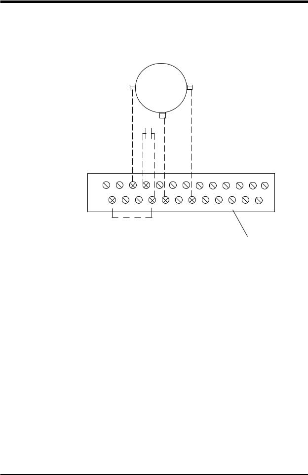
Connection Examples: Potentiometer Operation
Wiper (usually middle terminal)
stop/start
P24 RES RR |
F |
R S1 |
S2 |
S3 |
S4 |
RCH RCH LOW LOW |
|||
|
|
|
|
|
|
A |
C |
A |
C |
ST FM AM |
CC |
CC |
RX |
PP |
IV |
FP |
FLC |
FLB |
FLA |
Terminal Block
To run from a pot, the H3 must have:
1)Drive enable ("ST"-"CC" made)
2)Direction command ("F" or "R" to "CC" made)
3)Frequency reference ( wiper from pot is read via "RR" terminal )
4)LOCAL/REMOTE LED off (puts drive in remote mode).
Toggle the LOCAL/REMOTE button on keypad to turn LED off (with drive stopped).
Notes:
1)Use a 3K ohm pot (1 to 10 K ohms will work).
2)The drive will accel to commanded frequency when "F" or "R" to "CC" is made.
3)The drive will decel to 0.0 Hz when "F" or "R" to "CC" is broken.
4)Motor will coast to a stop if "ST" to "CC" is broken.
5)The above information applies to a H3 with factory default programming.
4 - 6
TOSHIBA
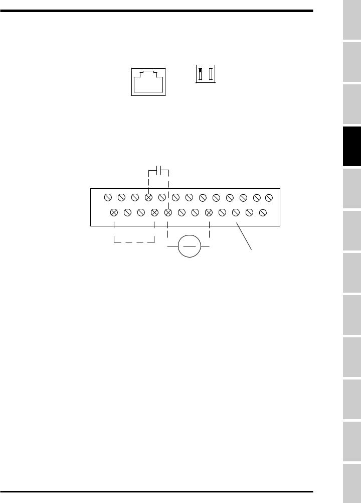
Connection Examples: 4 - 20mA Reference Operation
Phone Jack on Control Board |
I 5 |
|
Dipswitch
V 10
stop/start
P24 RES RR |
F |
R S1 |
S2 |
S3 |
S4 |
RCH RCH LOW LOW |
|||
|
|
|
|
|
|
A |
C |
A |
C |
ST FM AM |
CC |
CC |
RX |
PP |
IV |
FP |
FLC |
FLB |
FLA |
|
|
|
> |
|
|
|
( - ) |
|
(+) |
Terminal Block |
|||
|
|
|||||
|
|
|
|
|
|
|
4-20 mA Reference
To follow a 4-20 mA signal, the H3 must have:
1)"IV" dipswitch to the right of phone jack on control board (immediately under keypad) set to "I" position. "5/10" dipswitch has no effect in this scenario.
1)Drive enable ("ST"-"CC" made)
2)Direction command ("F" or "R" to "CC" made)
3)Frequency reference ( 4-20mA signal at "IV" terminal )
4)LOCAL/REMOTE LED off ( puts drive in remote mode)
Toggle the LOCAL/REMOTE button on keypad to turn LOCAL/REMOTE LED off.
Notes:
1)The drive will accel to the commanded frequency when "F" or "R" to "CC" is made.
2)The drive will decel to 0.0 Hz when "F" or "R" to "CC" is broken.
3)Motor will coast to a stop if "ST" to "CC" is broken.
4)The above information applies to a H3 with factory default programming.
5)Do not connect "CC" to ground.
Inspection
Precautions
Specifications
Wiring
Jumpers
Panel
Keypad
Parameters
Programming
Service
Dimensions
Index
4 - 7
TOSHIBA
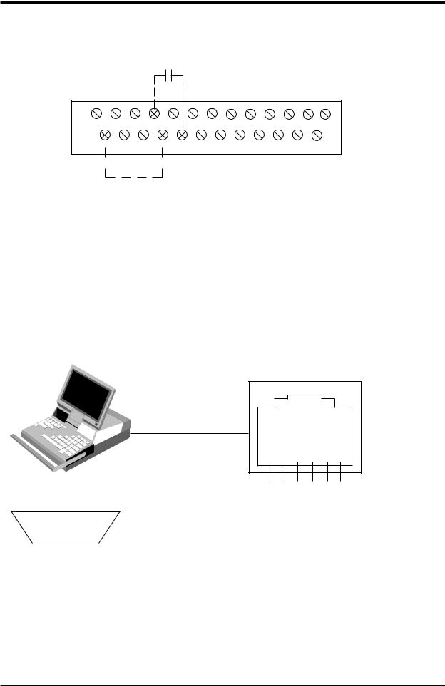
Connection Examples: Keypad Frequency Reference and Remote Stop/Start
dry contact (stop/start)
P24 RES RR |
F |
R S1 |
S2 |
S3 |
S4 |
RCH RCH LOW LOW |
|
|||
|
|
|
|
|
|
A |
C |
A |
C |
|
ST FM AM |
CC |
CC |
RX |
PP |
IV |
FP |
FLC |
FLB |
FLA |
Terminal Block |
|
|
|
|
|
|
|
|
|
|
|
To follow a local (keypad) reference with a remote stop/start, the H3 must have:
1)Drive enable ("ST"-"CC" made)
2)Direction command ("F" or "R" to "CC" made)
3)Frequency reference: Adjust on keypad with arrows. Press READ/WRITE to enter.
4)LOCAL/REMOTE LED off ( puts drive in remote mode)
Toggle the LOCAL/REMOTE button on keypad to turn LED off.
5) Programming: Set Item 282, FREQUENCY MODE SELECTION to "2". See page 8-28.
Notes:
1)The drive will accel to the commanded frequency when "F" or "R" to "CC" is made.
2)The drive will decel to 0.0 Hz when "F" or "R" to "CC" is broken.
3)Motor will coast to a stop if "ST" to "CC" is broken.
Connection Examples: RS232 Port


 <
<
Pinout for DB-9 on computer
(5) (4) (3) (2) (1)
(9) (8) (7) (6)
( looking head-on at male connector that plugs into computer )
Notes:
Pinout for G3 RJ11 RS232 port
>
6 5 4 3 2 1 ( facing front of G3 )
Connect DB9 pin 5 to RJ11 pin 3 Connect DB9 pin 3 to RJ11 pin 4 Connect DB9 pin 2 to RJ11 pin 2 Connect DB9 pin 7 to RJ11 pin 6 Connect DB9 pin 8 to RJ11 pin 1 Short DB9 pin 6 to DB9 pin 4
DB9 pin 1 and 9 and RJ11 pin 5 not used
1)Free RS232 programming/monitoring software is available from Toshiba. Contact your distributor for a copy and manual.
2)Do not insert/remove the phone plug into/from the H3 port when drive is powered.
3)Common 6 conductor phone cord can be used with an adaptor (6 conductor RJ11 female to DB9 female). The adapter is available from your Toshiba distributor or local electrical supply house.
4)"ST"-"CC" must be made.
4 - 8
TOSHIBA
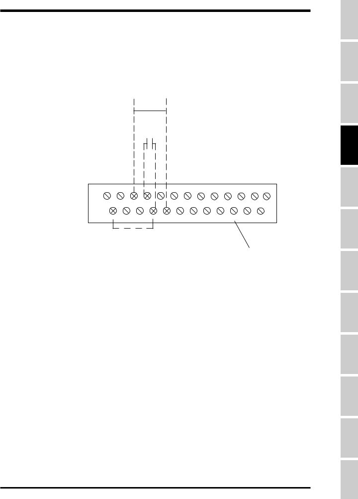
Connection Examples: 0-10 volt Reference Operation
0-10 V
(+)<Reference> ( - )
stop/start
P24 RES RR |
F |
R S1 |
S2 |
S3 |
S4 |
RCH RCH LOW LOW |
|||
|
|
|
|
|
|
A |
C |
A |
C |
ST FM AM |
CC |
CC |
RX |
PP |
IV |
FP |
FLC |
FLB |
FLA |
Terminal Block
To run from a 0-10 V reference, the H3 must have:
1)Drive enable ("ST"-"CC" made)
2)Direction command ("F" or "R" to "CC" made)
3)Frequency reference ( 0-10 V signal applied to "RR" terminal )
4)LOCAL/REMOTE LED off (puts drive in remote mode). Toggle the LOCAL/REMOTE button on keypad to turn LED off.
Notes:
1)The drive will accel to commanded frequency when "F" or "R" to "CC" is made.
2)The drive will decel to 0.0 Hz when "F" or "R" to "CC" is broken.
3)Motor will coast to a stop if "ST" to "CC" is broken.
4)The above information applies to a H3 with factory default programming.
5)Do not connect "CC" to ground.
Inspection
Precautions
Specifications
Wiring
Jumpers
Panel
Keypad
Parameters
Programming
Service
Dimensions
Index
4 - 9
TOSHIBA
SECTION 5: Jumper and Terminal Connections
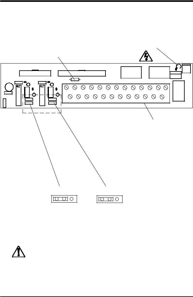
Terminal Board
The terminal printed wiring board is shown in the detail below. See Terminal Connections and Functions starting on page 5-3. This board is used in all drive sizes.
Charge LED
Fused Resistor for P24
P24 RES RR |
F |
R S1 |
S2 |
S3 |
S4 |
RCH RCH LOW LOW |
|||
|
|
|
|
|
|
A |
C |
A |
C |
ST FM AM |
CC |
CC |
RX |
PP |
IV |
FP |
FLC |
FLB |
FLA |
Terminal Block
0-1mA 4-20 mA |
0-1mA 4-20 mA |
JP3 |
JP4 |
Jumper JP3 is used to set AM terminal and
Jumper JP4 is used to set FM terminal.
CAUTION |
Turn off power to the drive before connecting or |
disconnecting any wiring to the terminal block. |
5 - 1
TOSHIBA
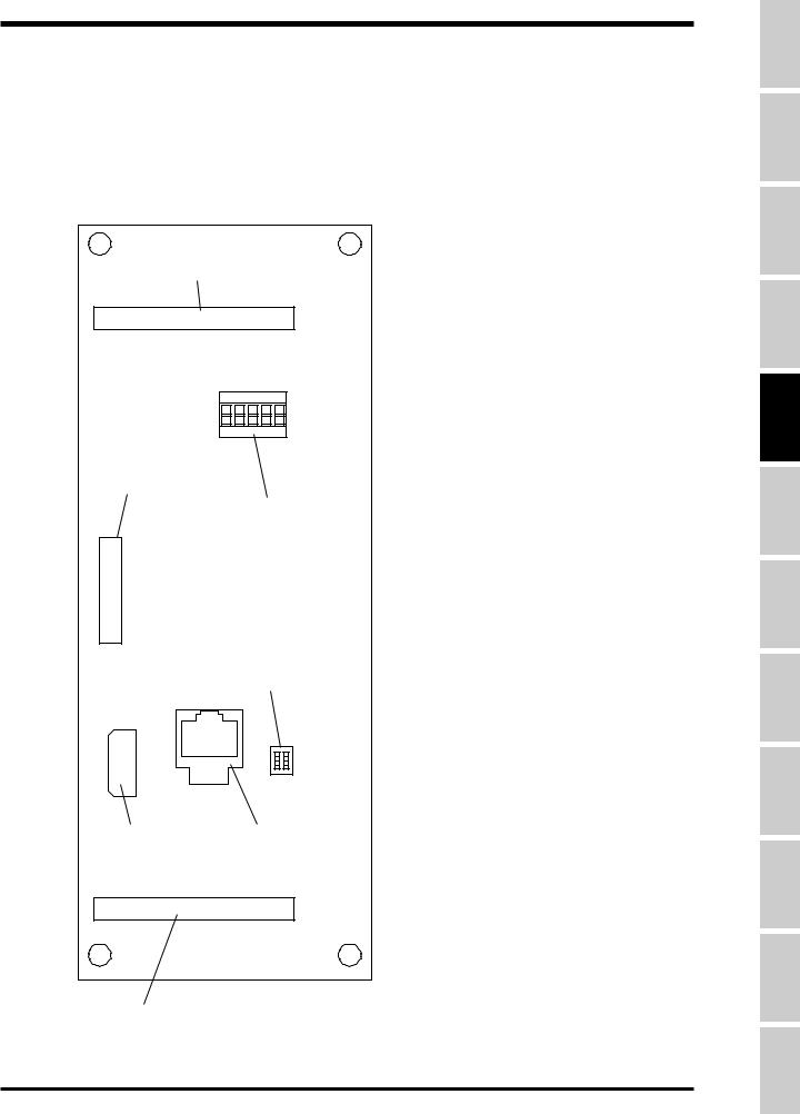
Control Board
The control printed wiring board is shown in the detail below. This control board is used in all drive sizes.
Ribbon cable |
|
|
I |
5 |
|
||
|
|
|
|
|
|
|
|
|
|
|
|
|
|
|
|
connector |
Dip Switch SW1 |
|
|
|
|
|
|
(back side) |
|
|
|
|
|
|
|
(Detail) |
|
|
|
|
|
|
|
|
|
|
|
|
|
|
|
|
|
|
|
|
|
|
|
|
|
V |
10 |
|
|||
|
When a 4(0)-20mA reference signal is input |
||||||
|
to terminal "IV", set switch SW1 to I |
||||||
|
When a 0-10 volt reference signal is input to |
||||||
|
terminal "IV", set SW1 to V |
||||||
Option board |
When a +/- 0-5 volt reference signal is input |
||||||
connector |
to terminal "RX", set SW1 to 5 |
||||||
(40-pin) |
|
|
|
|
|
|
|
Operation |
When a +/- 0-10 volt reference signal is |
||||||
panel |
input to terminal "RX", set SW1 to 10 |
||||||
connector |
|
|
|
|
|
|
|
Dip Switch
SW1 (see detail 1
this page)
Option |
RS-232 |
ROM |
Communication |
socket |
connector |
Ribbon cable |
Make connections to this board only with power off. |
connector |
|
Inspection
Precautions
Specifications
Wiring
Jumpers
Panel
Keypad
Parameters
Programming
Service
Dimensions
Index
5 - 2
TOSHIBA
Terminal Connections and Functions
Terminal |
Terminal functions |
Terminal |
|
name |
|
location |
|
L1, L2, L3 |
Line input supply terminals for models H3-2035 to H3-2330: |
|
|
(R, S, T) |
Connect to either 3ø, 50Hz, 200VAC or 3ø, 60Hz, 200 to 230VAC. |
|
|
|
Line input supply terminals for models H3-4055 to H3-420K: |
Terminal |
|
|
Connect to either 3ø, 50HZ, 400VAC or 3ø, 60Hz, 400 to 460VAC. |
||
|
Drives can be operated on single phase power with when |
block |
|
|
appropriately derated; contact Toshiba distributor for information. |
or |
|
|
|
bus bar |
|
T1, T2, T3 |
Motor output terminals. Connect these terminals to a 3-phase |
|
|
(U, V, W) |
induction motor of the proper voltage, current, and horsepower. |
|
|
PA, PB |
Braking resistor output terminals. Connect to an external dynamic |
|
|
|
braking resistor (available only on 30 HP and smaller drives). |
|
|
FLA, FLB, FLC |
Programmable relay contact output. The contact rating is |
|
|
|
250VAC - 2A. Default setting closes FLA-FLC and opens FLB-FLC |
|
|
|
when protective function has been activated. |
|
|
P24 |
Unregulated 24Vdc power supply (24Vdc, 50mA maximum). P24 is |
|
|
|
protected by fused resistor found on the terminal board (see p. 5-1). |
|
|
RCH(A & C) |
Programmable relay contact output. Standard setting closes |
|
|
|
contact when an acc/dec is complete, or when the output |
|
|
|
frequency is within a specified range. Contact rating is 250Vac - 2A. |
|
|
LOW(A & C) |
Programmable relay contact output. Standard setting closes |
|
|
|
contact when a preset low speed or a preset lower limit is |
Terminal |
|
|
reached. Contact rating is 250Vac - 2A. |
||
|
block |
||
|
|
||
PP |
10 VDC supply typically used to drive potentiometers. Wipers from |
(See page |
|
5-1) |
|||
|
pots typically connected to "RR" or "RX" terminals. |
||
|
|
||
FM* |
Programmable analog output. Outputs 0 - 1mA or 4 - 20mA (set by |
|
|
|
JP4 on terminal board (see section 5.1)). This terminal can |
|
|
|
be connected to an external analog meter. Use either an ammeter |
|
|
|
rated 1mA DC/20 mA DC at full scale or a voltmeter rated 7.5Vdc at |
|
|
|
full scale (true analog output). See page 9-23 for programming. |
|
|
AM* |
Programmable analog output. Outputs 0 - 1mA or 4 - 20mA (set by |
|
|
|
JP3 on terminal board (see section 5.1)). This terminal can |
|
|
|
be connected to an external analog meter. Use either an ammeter |
|
|
|
rated 1mA DC/20 mA DC at full scale or a voltmeter rated 7.5Vdc at |
|
|
|
full scale (true analog output). See page 9-23 for programming. |
|
|
FP |
Dedicated open-collector output. Pulses that are 48, 96, or |
|
|
|
360-times the output frequency are available according to the |
|
|
|
parameter settings (must connect external supply through pull-up |
|
|
|
resistor to measure output). |
|
* Do not make/break connections to these terminals with the drive powered.
5 - 3

TOSHIBA
Terminal Connections and Functions (cont'd)
Terminal |
Terminal functions |
|
|
Terminal |
|
name |
|
|
|
location |
|
|
|
|
|
|
|
CC |
This is the common return for all of the input and output terminals. |
|
|
|
|
(2-terminals) |
Do not connect this terminal to ground. |
Do not connect to GND(E). |
|||
|
|
|
|
|
|
RR |
Programmable analog input. Default setting allows user to |
|
|
|
|
|
input a 0 - 10VDC signal as a frequency command. Input has |
|
|
|
|
|
bias/gain adjustments. |
|
|
|
|
|
|
|
|
|
|
IV |
Programmable analog input. User can input a 0 - 10VDC signal or a |
|
|
|
|
|
4 - 20 mA DC signal as a frequency command (selection of current |
|
|
|
|
|
or voltage done via dipswitch on control board (see page 5-2). |
|
|
|
|
|
Input has bias gain adjustments. |
|
|
|
|
|
|
|
|
|
|
RX |
Programmable analog input. User can input a +/- 10VDC or a |
|
|
|
|
|
+/- 5VDC signal as a frequency command (see page 5-2). Input |
|
|
|
|
|
has bias/gain adjustments for forward and reverse operation. |
|
|
|
|
|
|
|
|
|
|
ST |
Programmable digital input. With default setting, shorting terminal |
|
|
|
|
|
to "CC" enables drive. Opening "ST" to "CC" coasts motor. |
|
|
|
|
|
|
|
|
|
|
F |
Programmable digital input. With default setting, shorting terminal |
|
Terminal |
||
|
to "CC" gives drive forward run command. Opening "F" to "CC" |
|
|||
|
decels motor to a stop. |
|
|
block |
|
|
|
|
|
(See page |
|
R |
Programmable digital input. With default setting, shorting terminal |
5-1) |
|
||
|
to "CC" gives drive reverse run command. Opening "R" to "CC" |
|
|
|
|
|
decels motor to a stop. |
|
|
|
|
|
|
|
|
|
|
S1 |
Programmable digital input. With default setting, shorting "S1" to |
|
|
|
|
|
"CC" gives drive preset speed frequency reference. |
|
|
|
|
|
|
|
|
|
|
S2 |
Programmable digital input. With default setting, shorting "S3" to |
|
|
|
|
|
"CC" gives drive preset speed frequency reference. |
|
|
|
|
|
|
|
|
|
|
S3 |
Programmable digital input. With default setting, shorting "S2" to |
|
|
|
|
|
"CC" gives drive preset speed frequency reference. |
|
|
|
|
|
|
|
|
|
|
S4 |
Programmable digital input. With default setting, shorting "S4" to |
|
|
|
|
|
"CC" gives drive preset speed frequency reference. |
|
|
|
|
|
|
|
|
|
|
RES |
Programmable digital input. With default setting, shorting "RES" to |
|
|
|
|
|
"CC" resets a tripped drive. |
|
|
|
|
|
|
|
|
|
|
Inspection
Precautions
Specifications
Wiring
Jumpers
Panel
Keypad
Parameters
Programming
Service
Dimensions
Index
5 - 4
TOSHIBA
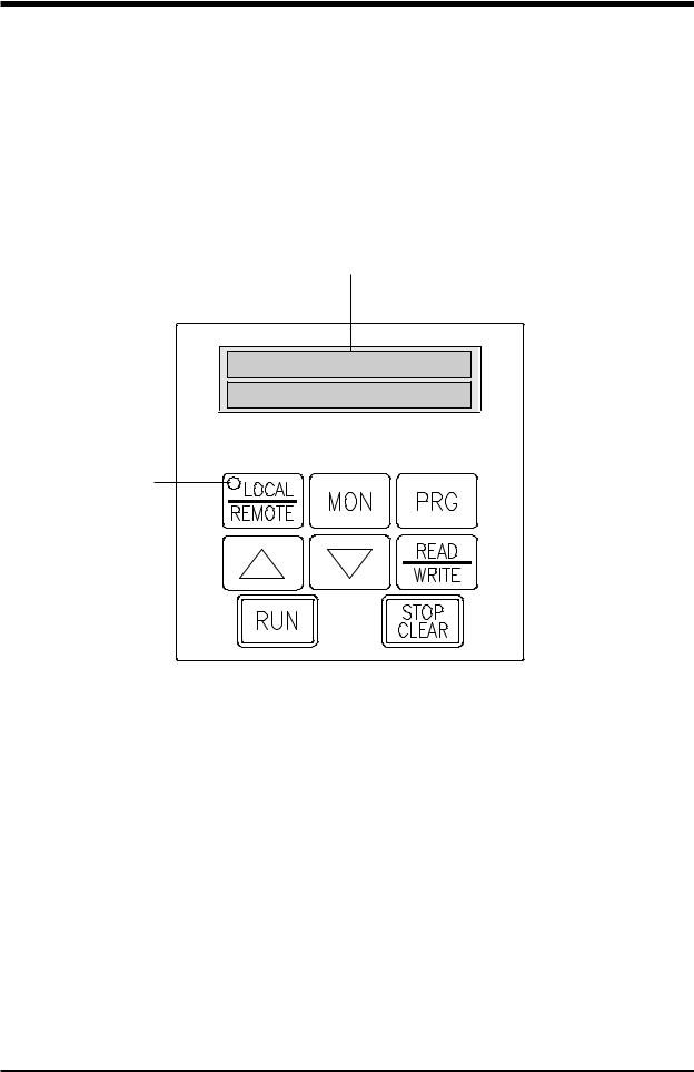
SECTION 6: Operating Panel
Operating Panel Layout
The operating panel enables the user to enable or disable the keypad, input commands from the keypad, and monitor the H3's operation on the liquid crystal display. The panel consists of the keypad, 20 character x 2-line LCD and a LED in the LOCAL/REMOTE button of the keypad. The illustration below shows the operating panel keypad layout and the locations of the keys and display.
Liquid crystal display
Local / remote
LED
6 - 1
 Loading...