


 Loading...
TOSHIBA
UNINTERRUPTIBLE POWER SYSTEM
THREE-PHASE 15/25/30/50 kVA UPS
4200FA CT/XT
User’s Manual
Document Number: 53878-006
Date: September 2007

TOSHIBA
4200FA CT/XT
THREE-PHASE 15/25/30/50 kVA
UNINTERRUPTIBLE POWER SYSTEM
CT-Internal Batteries
XTExternal Batteries or External Transformer
USER’S MANUAL
FOR MODELS
C42F3F150X#MBN
C42F3F150F#MBN
C42#3#150##MXN
C42F3F250X#MBN
C42F3F250F#MBN
C42#3#250##MXN
T42F3F300X#MBN
T42F3F300F#MBN
T42#3#300##MXN
T42F3F500XAMBN
T42F3F500F#MBN
T42#3#500##MXN
TOSHIBA INTERNATIONAL CORPORATION
INDUSTRIAL DIVISION
13131 West Little York Road
Houston, TX 77041-9990

TOSHIBA
IMPORTANT NOTICE
The Instructions contained in this manual are not intended to cover all of the details or variations in equipment or to provide for every possible contingency to be met in connection with installation, operation, or maintenance. Should further information be required or should particular problems arise which are not covered sufficiently the matter should be referred to the local TOSHIBA sales office.
The contents of this instruction manual shall not become a part of or modify any prior or existing equipment, commitment, or relationship. The sales contract contains the entire obligation of TOSHIBA INTERNATIONAL CORPORATION. The warranty contained in the contract between the parties is the sole warranty of TOSHIBA, and any statements contained herein do not create new warranties or modify the existing warranty.
Any Electrical or mechanical modifications to this equipment without prior written consent of the TOSHIBA will void all warranties and may void UL/CUL listing. Unauthorized modifications may also result in equipment damage, personal injury, or loss of life.
UNINTERRUPTIBLE POWER SYSTEM
If additional information or technical assistance is required call TOSHIBA Customer Support Center toll free at 1- 877-876-8773, or write to: Toshiba International Corporation, 13131 West Little York Road, Houston, TX 770419990 Attn: UPS Product Manager.
Please complete the following information for your records. Unless otherwise specified on the warranty card, the warranty period for the UPS or UPS part is 36 months from the shipment date (see bill of lading).
Unless otherwise specified on the warranty card, the warranty period for a UPS battery is 24 months from the shipment date (see bill of lading).
Keep this manual with the UPS equipment.
Job Number:
Model Number:
Serial Number:
Application:
Shipping Date:
Date of Installation:
Inspected By:
4200FA CT/XT User’s Manual |
2 |

TOSHIBA
|
TABLE OF CONTENTS |
|
IMPORTANT NOTICE....................................................................................................... |
2 |
|
TABLE OF CONTENTS.................................................................................................... |
3 |
|
Purpose and Scope of Manual....................................................................................... |
5 |
|
Contacting TOSHIBA Customer Support Center.......................................................... |
5 |
|
GENERAL SAFETY INSTRUCTIONS.............................................................................. |
6 |
|
EQUIPMENT WARNING LABELS ................................................................................... |
7 |
|
IMPORTANT SAFETY INSTRUCTIONS ........................................................................ |
10 |
|
1.0 |
Product Description............................................................................................. |
14 |
1.1 |
Theory of Operation ...................................................................................................................... |
14 |
1.2 |
Application and Use ...................................................................................................................... |
14 |
1.3 |
Power Backup ............................................................................................................................... |
14 |
1.4 |
Power Conditioning ....................................................................................................................... |
14 |
2.0 |
Unpacking/Inspection/Storage/Disposal............................................................ |
15 |
2.1 |
Unpacking the new UPS equipment 15/25/30 kVA:...................................................................... |
15 |
2.2 |
Unpacking the new UPS equipment 50 kVA:................................................................................ |
16 |
2.3 |
Inspection of the new UPS equipment.......................................................................................... |
16 |
2.3 |
Inspection of the new UPS equipment.......................................................................................... |
17 |
2.4 |
Storage of UPS equipment ........................................................................................................... |
17 |
2.5 |
Disposal......................................................................................................................................... |
17 |
3.0 |
Installation Precautions....................................................................................... |
18 |
3.1 |
Equipment Placement ................................................................................................................... |
18 |
3.2 |
System Preparation (Pre-Power) .................................................................................................. |
19 |
3.3 |
Operating Precautions .................................................................................................................. |
19 |
4.0 |
UPS Connections ................................................................................................. |
20 |
4.1 |
Power Connections ....................................................................................................................... |
20 |
4.1.1 Power Connections 15/25/30 kVA with Internal Batteries ............................................................ |
20 |
|
4.1.2 Power Connections 15/25/30 kVA with Internal Transformer .......................................................... |
21 |
|
4.1.3 Recommended Wire Size and Torque Requirements...................................................................... |
22 |
|
4.1.4 Power Connection Cable Routing and Conduit Placement 15/25/30 kVA....................................... |
23 |
|
4.2 |
Control Circuit and External Battery Interface Connections 15/25/30 kvA ................................... |
24 |
4.2.1 Recommended Wire Size and Torque Requirements...................................................................... |
24 |
|
4.3 |
Power Connections 50 kVA .......................................................................................................... |
25 |
4.3.1 Recommended Wire Size and Torque Requirements For UPS Input and Output Terminals....... |
26 |
|
4.3.2 Power Connection Cable Routing and Conduit Placement 50 kVA................................................. |
27 |
|
4.4 |
Control Circuit and External Interface Connections 50 kVA ......................................................... |
28 |
4.4.1 Recommended Wire Size and Torque Requirements .................................................................. |
28 |
|
4.5 |
Communication Interface .............................................................................................................. |
29 |
4.5.1 Remote Contact ............................................................................................................................ |
29 |
|
4.5.2 RS-232C........................................................................................................................................... |
30 |
|
4.5.3 UPS Shutdown (via RS-232C) ......................................................................................................... |
30 |
|
5.0 |
Specifications....................................................................................................... |
31 |
5.1 |
4200FA 15 / 25 kVA @ 208 VAC Input/ 208 VAC Output w/Internal Batteries ............................ |
31 |
5.2 |
4200FA 15/25 kVA w/Internal Transformer................................................................................... |
32 |
5.3 |
4200FA 30 kVA @ 208 VAC Input/ 208 VAC Output w/Internal Batteries ................................... |
33 |
5.4 |
4200FA 30 kVA w/Internal Transformer........................................................................................ |
34 |
5.5 |
4200FA 50kVA @ 208 VAC Input/ 208 VAC Output w/Internal Batteries .................................... |
35 |
5.6 |
4200FA 50kVA w/Internal Transformer......................................................................................... |
36 |
4200FA CT/XT User’s Manual |
3 |

TOSHIBA
6.0 |
Operating the UPS ............................................................................................... |
37 |
|
6.1 AC Input Mode (Normal Operation).................................................................................................. |
37 |
||
6.2 |
Bypass Mode.................................................................................................................................... |
38 |
|
6.4 |
Battery Backup Mode ....................................................................................................................... |
39 |
|
6.5 |
|
Battery Backup Time and Discharge Process .............................................................................. |
40 |
6.6 |
|
Battery Low Voltage Tolerances ................................................................................................... |
40 |
6.7 |
|
Battery Recharging........................................................................................................................ |
41 |
6.8 |
|
Front Panel Layout (All Units) ....................................................................................................... |
42 |
6.9 |
|
EPO (Emergency Power Off) Function ......................................................................................... |
42 |
6.10 |
|
Audible Alarm Functions ............................................................................................................... |
43 |
6.11 |
|
LED (Light Emitting Diode) Functions........................................................................................... |
43 |
6.11.1 |
LED (Light Emitting Diode) System Status ................................................................................... |
44 |
|
6.12 |
|
LCD (Liquid Crystal Display) Functions ........................................................................................ |
44 |
6.12.1 |
Line-1 System Messages.............................................................................................................. |
44 |
|
6.12.2 |
Line-2 System Fault Messages..................................................................................................... |
45 |
|
6.12.3 |
Line-3 System Messages.............................................................................................................. |
45 |
|
6.12.4 |
Line-4 System Messages.............................................................................................................. |
45 |
|
6.13 |
|
Initial Battery Charge..................................................................................................................... |
46 |
6.14 |
|
Start-up Procedure........................................................................................................................ |
47 |
6.15 |
|
Shutdown Procedure..................................................................................................................... |
48 |
6.16 |
|
Maintenance Bypass Procedure ................................................................................................... |
48 |
6.17 |
|
Keypad Overview .......................................................................................................................... |
50 |
6.18 |
|
Key Functions................................................................................................................................ |
51 |
6.18.1 |
MONI ............................................................................................................................................. |
51 |
|
6.18.2 |
IN................................................................................................................................................... |
51 |
|
6.18.3 |
OUT............................................................................................................................................... |
51 |
|
6.18.4 |
BATT Key ...................................................................................................................................... |
52 |
|
6.18.5 |
MENU, F1, ENTER, UP, & DOWN Keys ...................................................................................... |
52 |
|
6.18.6 |
BATT TEST Key............................................................................................................................ |
52 |
|
6.18.7 |
BUZZ STOP Key........................................................................................................................... |
53 |
|
6.18.8 |
RESET Key ................................................................................................................................... |
53 |
|
6.19 |
|
Menu Data Screens ...................................................................................................................... |
54 |
6.19.1 |
Settings for Calendar and Clock ................................................................................................... |
54 |
|
6.19.2 |
Adjusting the Buzzer Volume ........................................................................................................ |
54 |
|
6.19.3 |
Settings for Display Duration......................................................................................................... |
54 |
|
6.19.4 |
Run Switch Select ......................................................................................................................... |
55 |
|
6.19.5 |
Serial Com Station Address .......................................................................................................... |
55 |
|
6.19.6 |
Output Voltage Adjustment ........................................................................................................... |
56 |
|
6.19.7 |
Charge Mode Select ..................................................................................................................... |
56 |
|
6.19.8 |
Reset to Default Settings .............................................................................................................. |
57 |
|
6.20 |
|
Overload Operation....................................................................................................................... |
57 |
6.21 |
|
Backup History and Fault History.................................................................................................. |
58 |
7.0 |
|
UPS Protection System ....................................................................................... |
60 |
7.1 |
System Protection Features.......................................................................................................... |
60 |
|
7.2 |
System Protection Functions ........................................................................................................ |
60 |
|
8.0 |
|
Start-up/Scheduled Maintenance/Part Replacement......................................... |
61 |
8.1 |
Start-up.......................................................................................................................................... |
61 |
|
8.2 |
Preventive Maintenance................................................................................................................ |
61 |
|
8.3 |
Parts Replacement........................................................................................................................ |
62 |
|
9.0 |
External Dimensions / Shipping Dimensions / Weights.................................... |
63 |
|
|
|
9.1 External Dimensions 15/25/30 kVA ........................................................................................ |
63 |
9.2 |
External Dimensions 50kVA.......................................................................................................... |
64 |
|
9.3 |
Shipping Dimensions and Weights ............................................................................................... |
65 |
|
4200FA CT/XT User’s Manual |
4 |

TOSHIBA
Purpose and Scope of Manual
This manual provides information on how to safely install, operate, and maintain your TOSHIBA power electronics product. This manual includes a section on General Safety Instructions that describes the warning labels and symbols that are used throughout the manual. Read the manual completely before installing, operating, or performing maintenance on this equipment.
This manual and the accompanying drawings should be considered a permanent part of the equipment and should be readily available for reference and review. Dimensions shown in the manual are in metric and/or the English equivalent.
TOSHIBA reserves the right, without prior notice, to update information, make product changes, or to discontinue any product or service identified in this publication.
TOSHIBA is a registered trademark of TOSHIBA INTERNATIONAL CORPORATION. All other product or trade references appearing in this manual are registered trademarks of their respective owners.
TOSHIBA shall not be liable for technical or editorial omissions or mistakes in this manual. Nor shall it be liable for incidental or consequential damages resulting from the use of information contained in this manual.
This manual is copyrighted. No part of this manual may be photocopied or reproduced in any form without the prior written consent of TOSHIBA INTERNATIONAL CORPORATION.
© Copyright 2007 TOSHIBA INTERNATIONAL CORPORATION.
All rights reserved.
Printed in the U.S.A.
Contacting TOSHIBA Customer Support Center
The TOSHIBA Customer Support Center can be contacted to obtain help in resolving any Uninterruptible Power System problem that you may experience or to provide application information.
The center is open from 8 a.m. to 5 p.m. (CST), Monday through Friday. The Support Center’s toll free number in USA is (877) 867-8773.
You may contact TOSHIBA by writing to:
TOSHIBA INTERNATIONAL CORPORATION. INDUSTRIAL DIVISION
13131 West Little York Rd.
Houston, TX 77041-9990 Attn: UPS Product Manager
4200FA CT/XT User’s Manual |
5 |
TOSHIBA
GENERAL SAFETY INSTRUCTIONS
DO NOT attempt to install, operate, maintain or dispose of this equipment until you have read and understood all of the product safety information and directions that are contained in this manual.
Safety Alert Symbol
The Safety Alert Symbol indicates that a potential personal injury hazard exists. The symbol is comprised of an equilateral triangle enclosing an exclamation mark.
Signal Words
Listed below are the signal words that are used throughout this manual followed by their descriptions and associated symbols. When the words DANGER, WARNING and ATTENTION are used in this manual they will be followed by important safety information that must be carefully adhered to.
Warnings in this manual may appear in any of the following ways:
1)Danger warning ─ The danger symbol is an exclamation mark enclosed in a triangle, which precedes the word “DANGER.” The Danger warning symbol is used to indicate situations, locations, and conditions that exist and will cause serious injury or death.

 DANGER
2)Caution warning ─ The caution symbol is an exclamation mark enclosed in a triangle, which precedes the word “CAUTION.” The Caution warning symbol is used to indicate situations and conditions that can cause operator injury and/or equipment damage.

 CAUTION
3)Attention warning ─ The attention warning symbol is an exclamation mark enclosed in a triangle which precedes the word “ATTENTION.” The Attention warning symbol is used to indicate situations and conditions that can cause operator injury and/or equipment damage.

 ATTENTION
Other warning symbols may appear along with the Danger and Caution symbol and are used to specify special hazards. These warnings describe particular areas where special care and/or procedures are required in order to prevent serious injury and possible death.
1)Electrical warning ─ The electrical warning symbol is a lighting bolt enclosed in a triangle. The Electrical warning symbol is used to indicate high voltage locations and conditions that may cause serious injury or death if the proper precautions are not observed.
2)Explosion warning ─ The explosion warning symbol is an explosion image enclosed in a triangle. The Explosion warning symbol is used to indicate locations and conditions where molten exploding parts that may cause serious injury or death if the proper precautions are not observed.
4200FA CT/XT User’s Manual |
6 |
TOSHIBA
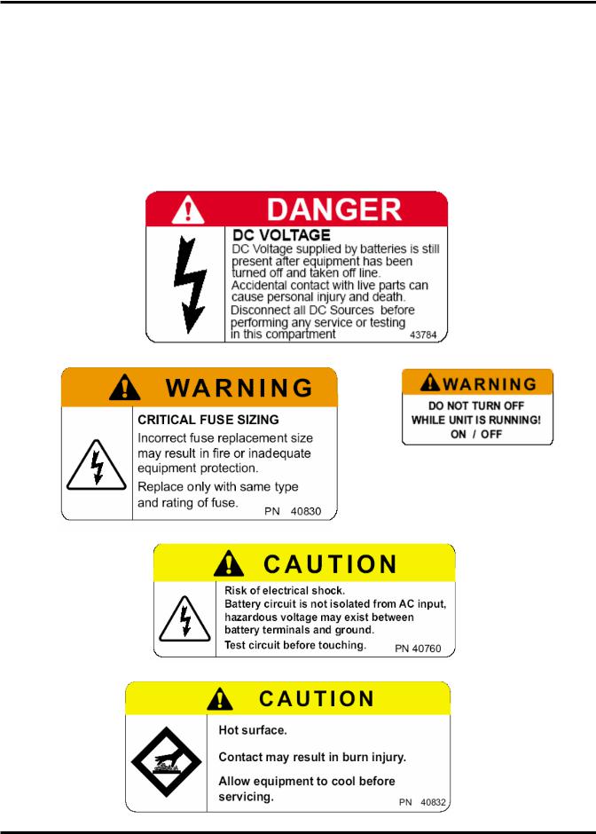
EQUIPMENT WARNING LABELS
DO NOT attempt to install, operate, maintain or dispose of this equipment until you have read and understood all of the product warnings and user directions that are contained in this instruction manual.
Shown below are examples of warning labels that may be found attached to the equipment. DO NOT remove or cover any of the labels. If the labels are damaged or if additional labels are required, contact your TOSHIBA representative for additional labels.
The following are examples of the warning labels that may be found on the equipment. The labels are there to provide useful information or to indicate an imminently hazardous situation that may result in serious injury, severe property and equipment damage, or death if the instructions are not followed.
4200FA CT/XT User’s Manual |
7 |
TOSHIBA
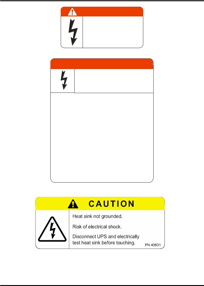
DANGER
RISK OF ELECTRIC SHOCK
Capacitors stay charged after power has been shut off.
Accidental contact with live parts can cause personal injury and death.
Turn off and lock out all power sources. Wait at least five (5) minutes for power to dissipate then check voltage before servicing. 39561
 DANGER
HAZARDOUS VOLTAGES
Hazardous voltages are used in the operation
of this equipment and could cause severe personal injury or loss of life.
The following precautions should be observed to reduce the risk of injury or death.
Only qualified technicians familiar with this equipment and the information supplied with it should be permitted to install and
operate this equipment.
Installation of electrical equipment must be done in accordance with National Electrical Code and any other state
or local codes. Proper grounding and conductor sizing must be installed for safe operation.
During operation, keep all covers in place and cabinet doors shut.
When performing visual inspections and maintenance, if possible, be sure the UPS is turned off and the incoming
AC feed is turned off and locked out.
The UPS and Battery Cabinet will have hazardous voltages present even after the AC feed is turned off.
If it is necessary to make measurements with the power on, do not touch any electrical connection points. Remove
all jewelry from wrists and fingers. Make sure test equipment is in good, safe operating condition.
While servicing, stand on some type of insulation, and be sure not to be grounded.
Follow the safety instructions given in the equipment manual carefully and observe all danger, warning and caution notices.
40308
4200FA CT/XT User’s Manual |
8 |

TOSHIBA
NOTE: This Label for Battery Units Only
4200FA CT/XT User’s Manual |
9 |
TOSHIBA
IMPORTANT SAFETY INSTRUCTIONS
SAVE THESE INSTRUCTIONS
This manual contains important instructions that should be followed during the installation, maintenance, and operation of the UPS and its batteries to assure safe and proper operation
1.Turn off, lockout, and tagout all power sources before connecting the power wiring to the equipment or when performing maintenance.
2.Hardwire type UPS units are not equipped with an over-current protection device, nor do they have an output disconnect for the ac output. Therefore, a user-installed circuit breaker should be provided between the UPS output and the load input.
3.Battery servicing should be performed by a qualified TOSHIBA Representative only.
4.Unauthorized personnel should not service batteries.
5.Contact your nearest TOSHIBA authorized service center for battery replacement.
Qualified Personnel ONLY!
Qualified Personnel is one that has the skills and knowledge relating to the construction, installation, operation, and maintenance of the electrical equipment and has received safety training on the hazards involved (Refer to the latest edition of NFPA 70E for additional safety requirements).
Qualified Personnel shall:
1.Have read the entire operation manual.
2.Be trained and authorized to safely energize, de-energize, ground, lockout and tag circuits and equipment, and clear faults in accordance with established safety practices.
3.Be trained in the proper care and use of protective equipment such as safety shoes, rubber gloves, hard hats, safety glasses, face shields, flash clothing, etc., in accordance with established safety practices.
4.Be trained in rendering first aid.
5.Be knowledgeable of batteries and the required handling and maintenance precautions.
For further information on workplace safety visit www.osha.gov.
Refer to the Battery System Manual for details on operating and maintaining the battery units for each system.
UPS System’s output is not equipped with an over-current protection device, or an output disconnect for the AC output; therefore, a circuit breaker should be provided, by the user, between the UPS output and the critical load input. This minimum current rating for the device should be rated as follows:
|
15 kVA |
25 kVA |
30 kVA |
50 kVA |
Rated Output |
Rating |
Rating |
Rating |
Rating |
208/120 VAC |
240 V, 60 A |
240 V, 90 A |
240 V, 110 A |
240 V, 175 A |
220/127 VAC |
240 V, 50 A |
240 V, 90 A |
240 V, 110 A |
240 V, 175 A |
240 VAC |
240 V, 50 A |
240 V, 80 A |
240 V, 90 A |
240 V, 175 A |
380/220 VAC |
480 V, 30 A |
480 V, 50 A |
480 V, 60 A |
480 V, 100 A |
480/277 VAC |
480 V, 25 A |
480 V, 40 A |
480 V, 50 A |
480 V, 80 A |
600 VAC |
600 V, 20 A |
600 V, 35 A |
600 V, 40 A |
600 V, 70 A |
4200FA CT/XT User’s Manual |
10 |
TOSHIBA
The maximum ambient temperature in which the Uninterruptible Power System (UPS) should be operated is 104 °F (40 °C) without batteries, and 89 °F (32 °C) if the battery cabinet is subject to the same ambient temperature as the UPS. The nominal battery voltage for all internal battery models is 288 VDC. The nominal battery voltage for all external battery models is 288 VDC.
An Authorized TOSHIBA Representative who is knowledgeable of batteries and the required precautions should perform service on the batteries. Keep unauthorized personnel away from batteries.
Refer to the Battery System Manual, when scheduling maintenance or battery replacement.
Refer to the Battery System Manual when scheduling battery maintenance or battery replacement.
DANGER |
Misuse of this equipment could result in injury and equipment damage. |
In no event will TOSHIBA be responsible or liable for direct, |

 indirect, or consequential damage or injury that may result from the use of this equipment.
CAUTION |
Do not dispose of the batteries in a fire. The batteries may |
explode. |

 CAUTION

 CAUTION

 CAUTION
WARNING
WARNING
Do not open or mutilate the batteries. Released electrolyte is toxic and harmful to the eyes and skin.
This unit contains sealed lead acid batteries. An annual preventative maintenance should be performed by an authorized technician. Failure to do so could result in batteries exploding and emitting gasses. and or flame.
Do not open or mutilate the batteries. Released electrolyte is toxic and harmful to the eyes and skin.
Failure to replace a battery before it becomes exhausted may cause the case to crack, possibly releasing electrolytes from inside the battery, and resulting in secondary faults such as odor, smoke, and fire.
Only personnel knowledgeable of batteries and the required precautions should perform installation and servicing of batteries. Keep Unauthorized personnel away from the batteries.


 WARNING
DANGER
A qualified service technician must do proper maintenance to the battery system of this unit. This is essential for the safety and reliability of your UPS system. Refer to service manual.
A battery can present a risk of electrical shock and high short circuit current.
4200FA CT/XT User’s Manual |
11 |

TOSHIBA
The following precautions should be observed when working with batteries.
1)Verify that the “UPS” is off and that the Input Circuit Breaker is in the off position.
2)Remove watches, rings, jewelry, or other metal objects.
3)Use tools with insulated handles to prevent accidental shorts.
4)Wear rubber gloves and boots.
5)Do not lay tools or metal parts on top of batteries.
6)Determine if the battery is grounded. If grounded, remove source of the ground.
Contact with any part of a grounded battery can result in an electrical shock.
Electrical shock will be reduced if grounds are removed during installation and maintenance.
7)Verify circuit polarities prior to making connections.
8)Disconnect charging source and load prior to connecting or disconnecting terminals.
9)VRLA batteries contain an explosive mixture of hydrogen gas. Do not smoke; create a flame or a spark in the immediate area of the batteries. This includes static electricity.
10)Do not attempt to open the batteries in order to add water or sample the specific gravity of the electrolyte. The batteries are valve regulated lead acid type and such servicing is not possible without damaging the battery.
11)Use proper lifting means when moving batteries and wear all appropriate safety clothing and equipment.
12)Dispose of lead acid batteries through proper channels in accordance with Local, State and Federal EPA Regulations.
To be performed by Qualified Personnel only.
1)Verify that the UPS is off and that the power cord is disconnected from the power source.
2)Remove watches, ring, jewelry, or other metal objects.
3)Use tools with insulated handles to prevent inadvertent shorts.
4)Wear rubber gloves and boots.
5)Do not place tools or any metal parts on top of batteries.
6)Determine if the battery is inadvertently grounded. If inadvertently grounded, remove source of ground.
Contact with any part of a grounded battery can result in electrical shock.
The likelihood of shock will be reduced if such grounds are removed prior to installation or maintenance.
4200FA CT/XT User’s Manual |
12 |

TOSHIBA
INSTRUCTIONS IMPORTANTES CONCERNANT
LA SÉCURITÉ
CONSERVER CES INSTRUCTIONS |
Cette notice contient des |
|
instructions importantes |
||
ATTENTION |
|
concernant la sécurté |
Un battery puet présenter un risque de choc électrique, de brûlure |
||
par transfert d’ énergie. |
|
|
ATTENTION |
L’élimination des batteries est règlementèe. Consultar les codes |
|
locaux à cet effet |
|
|
4200FA CT/XT User’s Manual |
13 |

TOSHIBA
1.0Product Description
1.1Theory of Operation
An Uninterruptible Power Supply (UPS) is a system that is installed between the commercial power and the critical load. The UPS provides steady AC output power during commercial power fluctuations and interruptions.
During “Normal Operation” the UPS utilizes commercial AC power and removes high voltage spikes and transients caused by switching and faults on the utility. The result of this process is maximum power conditioning and regulation.
If the AC power supplied to the UPS drops below a specified voltage level, the unit's batteries automatically begin supplying power instead of receiving it. This insures that the loads connected to the UPS continue to receive power without interruption. This power is provided for a long enough time so that the load can be shut down in an orderly fashion. This prevents loss of data and possible damage to both hardware and software.
When the AC input power becomes available again, the operation returns to normal and the batteries begin to recharge for the next power interruption.
1.2Application and Use
The TOSHIBA 4200FA On-Line, Uninterruptible Power Systems (UPS) provide continuous computer grade isolated AC power in a compact, efficient, high performance unit. The UPS assures safe, reliable operation of critical office equipment, ranging from personal computers to mini-computers to local area networks (LAN). All units feature an audible alarm that sounds if the battery voltage drops below the standard during use. This is an additional aid to help in retaining valuable data and equipment. All units are capable of interfacing to a computer network.
1.3Power Backup
During an electrical power failure the UPS batteries automatically supply DC power to the inverter that supports the load equipment, without interruption. For example, when used to support a computer, the UPS’s back up assures additional time to complete your activity, store data and initiate an orderly shutdown after a power failure occurs.
1.4Power Conditioning
While commercial power is present, the UPS supplies conditioned power to the load while maintaining its batteries in a charged condition. The UPS protects the connected load against the normal, everyday problems associated with heavy use of raw commercial power, including power sags, surges, signal interference, and spikes. In addition, the models with transformers provide total isolation to reduce the common and normal mode noises. This adds further protection to keep power-line problems from reaching your load, where it can cause equipment to operate erratically, or damage hardware and software.
4200FA CT/XT User’s Manual |
14 |
TOSHIBA
2.0Unpacking/Inspection/Storage/Disposal
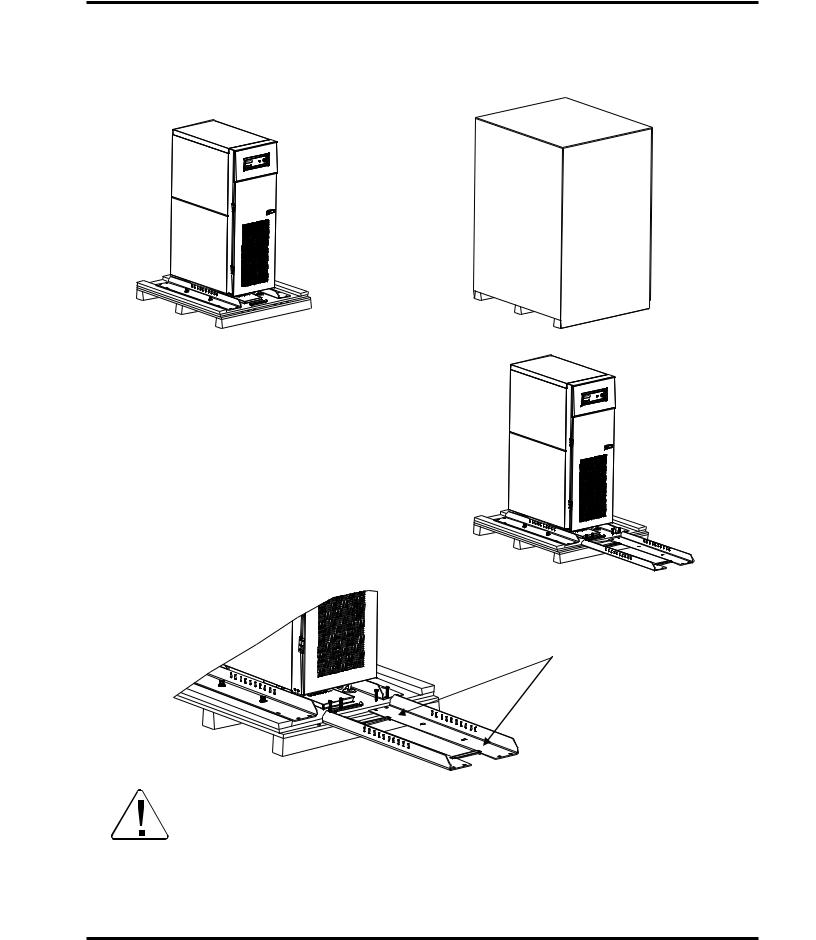
2.1Unpacking the new UPS equipment 15/25/30 kVA:
Upon receipt of the UPS, a careful inspection for shipping damage should be made. Units shipped within North America are shrink-wrapped; those outside North America are crated.
1. Remove packing material.
1a. For international units, remove the screws that attach the shipping crate to the pallet.
Remove the crate and foam packing material.
2.Unbolt the rails from both the unit and the shipping pallet.
Place the rails on the front of the pallet.
Use the four 1/2 x 3" bolts to
secure the rails to the shipping pallet.
Attach the rails as shown in the front to the front of the pallet.
3. Place the tie brackets in the slots at the lower end of the ramps. SLOWLY roll the unit down the ramp.
TOP HEAVY EQUIPMENT. IMPROPER LIFTING CAN RESULT IN INJURY OR
DANGER DEATH. LIFT AND MOVE CAREFULLY AND ONLY WITH ADEQUATE EQUIPMENT AND TRAINED PERSONNEL. THIS EQUIPMENT WILL TIP OVER
EASILY UNTIL FIXED IN PLACE.
4200FA CT/XT User’s Manual |
15 |
TOSHIBA
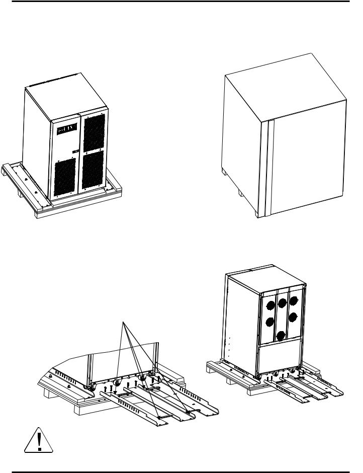
2.2Unpacking the new UPS equipment 50 kVA:
Upon receipt of the UPS, a careful inspection for shipping damage should be made. Units shipped within North America are shrink-wrapped; those outside North America are crated.
1.Remove packing material.
1a. For international units, remove the screws that attach the shipping crate to the pallet. Remove the crate and foam packing material.
2.Unbolt the rails from both the unit and the shipping pallet.
Place the rails on the front of the pallet.
Use the four 1/2 x 3" bolts to secure the rails to the shipping pallet.
Attach the rails as shown in the front to the front of the pallet.
3. Place the tie brackets in the slots at the lower end of the ramps. SLOWLY roll the unit down the ramp.
TOP HEAVY EQUIPMENT. IMPROPER LIFTING CAN RESULT IN INJURY OR DEATH.
DANGER LIFT AND MOVE CAREFULLY AND ONLY WITH ADEQUATE EQUIPMENT AND TRAINED PERSONNEL. THIS EQUIPMENT WILL TIP OVER EASILY UNTIL FIXED IN PLACE.
4200FA CT/XT User’s Manual |
16 |

TOSHIBA
2.3Inspection of the new UPS equipment After Unpacking:
1)Check the unit for loose, broken, bent or other damaged parts. If damage has occurred during shipment, keep all packing materials for return to the shipping agent. The equipment warranty will not apply to units that are damaged during shipment.
2)Check to see that the rated capacity and the model number specified on the nameplate conform to the order specifications.
2.4Storage of UPS equipment
If the UPS equipment is to be subject to long or short-term storage, the following guidelines should be used.
Avoid:
1)Storage in sites subject to extreme changes in temperature or high humidity.
2)Storage in sites subject to exposure of high levels of dust or metal particles.
3)Storage on inclined floor surfaces or in sites subject to excessive vibration.
Before storing:
1)Charge the system's batteries.
2)Perform a complete system shutdown as described in section 6.15 of this manual.
Storing:
1)Store within a temperature range of - 4 – 104 °F (-20 – 40 °C).
2)For best results, store the UPS in the original shipping container and place on a wood or metal pallet.
3)The optimum storage temperature is 70 °F (21 °C). Higher ambient temperatures cause UPS batteries to need recharging more frequently.
4)If stored in an ambient temperature under 68 °F (20 °C), recharge the batteries every 9 months.
5)If stored in an ambient temperature of 68 – 86 °F (20 – 30 °C), recharge the batteries every 6 months.
6)If stored in an ambient temperature of 86 – 104 °F (30 – 40 °C), recharge the batteries every 3 months.
2.5Disposal
Please contact your state environmental agency for details on proper disposal of electrical components and packaging in your particular area.
ATTENTION |
It is ILLEGAL to dump lead-acid batteries in landfills or dispose of |
improperly. Please help our Earth by contacting the environmental |
|
|
protection agencies in your area, the battery manufacturer, or call TOSHIBA |
|
toll-free at (877) 867-8773 for more information about recycling batteries. |
4200FA CT/XT User’s Manual |
17 |
TOSHIBA
3.0 Installation Precautions
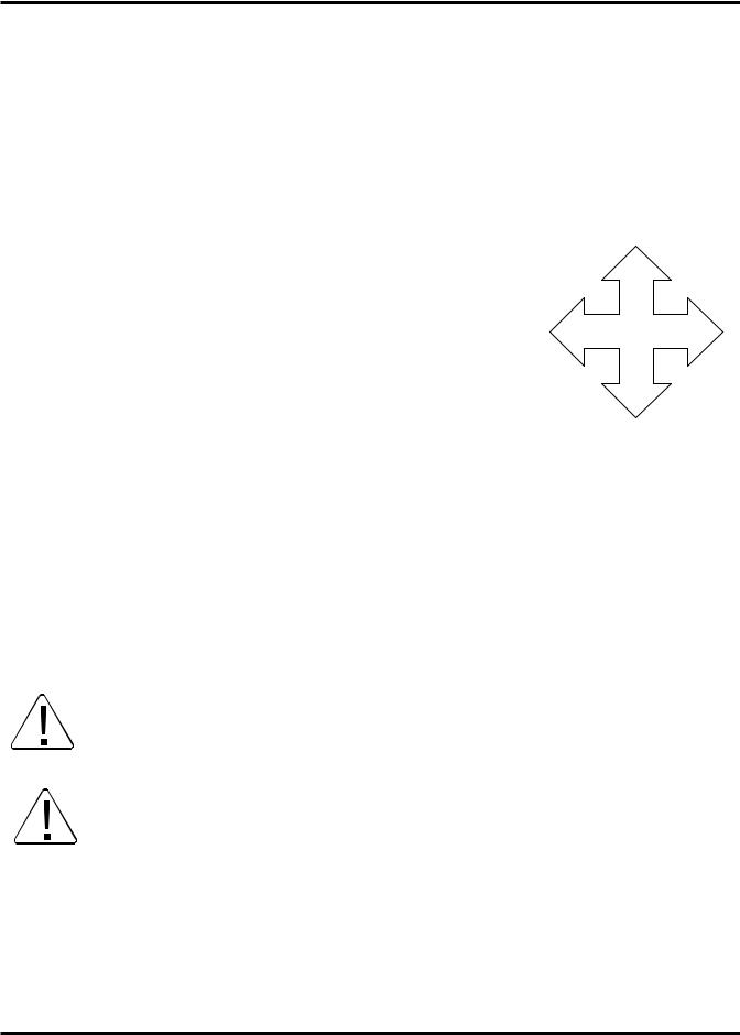
Based on the 4200FA UPS external dimensions and the way the outer panels are removed; minimum amounts of unobstructed space around the unit are necessary for ventilation and maintenance access. The following section and Fig. 3.1 shows the minimum clearances required for proper UPS site installation.
3.1Equipment Placement
1)Do not install the UPS on an inclined surface, or areas that are subject to frequent vibrations or jolting. This could damage UPS circuits.
REAR 6” (152mm)
2)Do not allow liquids or foreign objects to get inside the UPS.
3)Allow at least 20” (500 mm) on the front side and 6" (152 mm) on the rear and sides of the UPS unit for air ventilation and maintenance access.
4)Do not install the UPS in a location that is subject to high humidity. Also, do not install the unit in areas that are exposed to direct sunlight, or contaminated areas subject to high levels of airborne dust, metal particles, or flammable gasses.
5)Verify the ventilation and air conditioning system at the site is capable of removing the heat generated by the UPS.
Ambient temperature range for operating the UPS is 32 – 104 °F (0 – 40 °C); 77 °F
(25 °C) is the recommended operating temperature for maximum battery life.
6)Avoid installation near sources of electrical noise. Always make sure that the unit's ground is intact to prevent electrical shock and help prevent electrical noise.
7)This UPS generates and radiates radiofrequency energy during operation. Although RFI noise filters are installed inside the unit there is no guarantee that the UPS will not influence some sensitive devices, which are operating in near proximity. If such interference occurs, the UPS should either be installed farther away from the affected equipment and/or powered from a different source than the affected equipment.
LEFT |
RIGHT |
6” (152mm) |
6” (152mm) |
FRONT 20” (500mm)
Fig 3.1
4200FA CT/XT User’s Manual |
18 |

TOSHIBA
3.2System Preparation (Pre-Power)
Before connecting the UPS to a power source; move the Circuit Breakers (ON/OFF), on the front panel, to the OFF position and move the operation STOP/RUN key switch, on the front panel, to the STOP position.
3.3Operating Precautions
1)The UPS should not be powered up until the entire User’s Manual has been reviewed, and understood.
2)The input power source voltage must be within +10% to -15% of the rated input voltage to initially start the UPS. The input frequency must be within the rated input frequency range. Voltages and frequencies outside of the permissible range may cause internal protection devices to activate.
3)The UPS should not be used with a load whose rated input is greater than the rated UPS output.
4)Do not use the UPS to provide power to motors that require high starting current or a long starting time such as vacuum cleaners and machine tools.
5)Do not insert metal objects or combustible materials in the unit's ventilation slots.
6)Do not place, hang, or paste any objects on the top or on the exterior surfaces of the UPS.
7)The capacitors of the UPS maintain a residual charge for a while after turning off the UPS. The required discharge time for each UPS typeform is provided via a cabinet label and a CHARGE LED. Wait for at least the minimum time indicated on the label and ensure that the CHARGE LED has gone out before removing the front panel of the UPS once the UPS power has been turned off.
8)Do not attempt to disassemble, modify, or repair the UPS. Call TOSHIBA Service for repair information.
9)Turn the power on only after attaching ALL the covers and DO NOT remove any covers of the UPS when the power is on.
10)If the UPS should emit smoke or an unusual odor or sound, turn the power off immediately.
11)The heat sink and other components may become extremely hot to the touch. Allow the unit to cool before coming into contact with these items.
12)Warning signs should be placed on or near the load to let people know that the load is being powered by the UPS.
4200FA CT/XT User’s Manual |
19 |
TOSHIBA
13)Additional warnings and notifications shall be posted at the equipment installation location as deemed required by Qualified Personnel.
CAUTION |
When the UPS is in the Inverter mode, turning the breaker to the OFF |
position will cause the unit to go into the battery backup mode. The |

 UPS will continue to provide power to the load. The unit must be in Bypass mode and then the breaker turned to the OFF position for the UPS to shut down power to the load.
CAUTION |
Do not EPO (Emergency Power OFF) the UPS and then reset the |
breaker until the UPS has been fully discharged. The UPS could be |
|
|
damaged if the unit is not fully powered down before the breaker is |
|
reset. |
4.0UPS Connections
4.1Power Connections
4.1.1Power Connections 15/25/30 kVA with Internal Batteries
The following illustrates the wiring connections from the power distribution panel (not part of the UPS) to the terminal block of the 15/25/30 kVA UPS Models
CUSTOMER-PROVIDED AC DISTRIBUTION PANEL
TB1
INPUT GROUND RESISTANCE
LESS THAN 10 OHMS
Optional Bypass Input: 3-phase, 3-Wire
*208 V requires 3-phase, TB4
4-Wire Wye
4200FA CT/XT User’s Manual |
20 |
Loading...