


TMC-212 |
Residential and Commercial Irrigation System Controller |
User’s Guide |

Congratulations! You have chosen one of the most sophisticated and technologically advanced irrigation system controllers available for residential and light-commercial applications.
Your new Toro TMC-212 controller features:

 Flexible Station Count from 2 to 12 Stations with 2-station Expansion modules:

 Standard and High-surge Expansion Modules

 Locking Outdoor Cabinet

 Automatic Pump Start/Master Valve Control Circuit

 365-day Calendar

 3 Fully-independent Watering Programs Featuring:

 4 Start Times

 3 Watering Day Schedule Options:

 7-day Calendar

 7-day Interval with Day Exclusion

 Odd/Even Days with Day Exclusion

 Station Time from 1 Minute to 4 Hours

 Pump Start/Master Valve Timing Control

 Well Recovery/Station Delay Time

 Season Adjust from 10 to 200%

 Rain Delay from 1—7 Days

 Automatic Program/Start Time Stacking

 Rain Sensor Ready:

 Compatible with All Rain Sensor Types

 Sensor Circuit Bypass Switch

 Remote Control Ready

 Automatic Circuit Protection—Eliminates Fuse
 Non-volatile Program Memory—Eliminates Battery
The TMC-212 controller features several unique and helpful operating characteristics. To take advantage of these features, spend just a few minutes to browse through this manual to familiarize yourself with your new controller.
This booklet is divided into six main sections:
•The first section provides a brief description of the controller components and display elements.
•The second section takes you step-by-step through the installation process.
•The next section provides fundamental irrigation system operation, basic controller operation as well as specific programming and operating characteristics of the TMC-212.
•The fourth section takes you step-by-step through the programming process.
•The fifth section explains the various methods of automatic and manual controller operations.
•Finally, an appendix provides helpful reference information, troubleshooting, specifications and warranty information.
A convenient watering schedule form (affixed to the cover of the outdoor model controller and included on page 20) enables you to record and keep specific station and watering program information on hand with your controller.
The Quick Reference Guide provided with your User Guide should also be kept with your controller. The booklet fits conveniently between the cabinet back and the mounting bracket of the Indoor model. For Outdoor model controllers, hang the booklet on the hook provided inside the cabinet cover.

Table of Contents |
|
Controller Components......................................... |
2 |
Controller Installation |
|
■ Indoor Model Installation ................................ |
6 |
Connecting the Valves .................................... |
7 |
Connecting a Pump Start Relay...................... |
8 |
Connecting the Transformer ........................... |
8 |
■ Outdoor Model Installation ............................. |
9 |
Preparing the Cabinet for Installation.............. |
9 |
Installing the Cabinet..................................... |
10 |
Connecting the Valves .................................. |
11 |
Connecting a Pump Start Relay.................... |
12 |
Connecting the Power Source ...................... |
13 |
■ Connecting a Rain Sensor............................... |
13 |
Getting Started |
|
■ Irrigation System Basics .................................. |
14 |
■ Watering Program Basics ................................ |
15 |
■ Watering Program Details................................ |
16 |
■ Planning Your Watering Schedule................... |
18 |
■ Filling Out the Watering Schedule Form.......... |
18 |
Watering Schedule Form .............................. |
20 |
Programming the Controller |
|
■ About the Controller Memory........................... |
21 |
■ Setting the Current Time and Day or Date ...... |
21 |
■ Setting the Watering Day Schedule................. |
22 |
Setting a Calendar Schedule ........................ |
22 |
Setting an Interval Schedule ......................... |
23 |
Setting an Odd or Even Schedule................. |
24 |
Using the Day Exclusion Feature ................. |
25 |
■ Turning Off a Program .................................... |
26 |
|
||
■ Setting Program Start Times ........................... |
27 |
|
||
■ Setting Station Times....................................... |
28 |
|
||
■ Setting Pump/Master Valve and |
|
|
||
Well Recovery Controls ................................... |
28 |
|
||
Controller Operations |
|
|
||
■ Automatic Mode ............................................ |
30 |
|
||
■ Manual Mode ................................................. |
31 |
|
||
|
Operate Watering Program(s)....................... |
31 |
|
|
|
Operate Stations ........................................... |
31 |
|
|
|
Watering Control Features ............................ |
32 |
|
|
|
|
Pause Watering .......................................... |
32 |
|
|
|
Resume Watering ....................................... |
32 |
|
|
|
Cancel Watering ......................................... |
32 |
|
|
|
Skip Stations............................................... |
32 |
|
|
|
Adjust the Station TIme During Operation .. |
33 |
|
■ Rain Delay Feature.......................................... |
33 |
|
||
■ Season Adjust Feature .................................... |
34 |
|
||
■ Turn Off Operation........................................... |
35 |
|
||
Appendix |
|
|
||
■ Clearing the Program Memory......................... |
36 |
|
||
■ About Automatic Circuit Protection .................. |
37 |
|
||
■ Adding a 2-Station Expansion Module............. |
37 |
|
||
■ Using Pump/Master Valve Controls................. |
38 |
|
||
■ Troubleshooting ............................................... |
40 |
|
||
■ Specifications................................................... |
41 |
|
||
■ Warranty .......................................................... |
42 |
1 |
||
■ Electromagnetic Compatibility ......................... |
42 |
|||
Controller Components
Controller Components
2

Controller Components
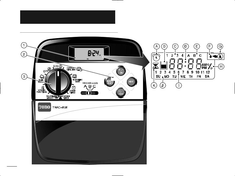
The following are brief descriptions of the controller components and display elements. Each of these items will be explained in further detail within the appropriate programming, operating and installation sections of this guide.
1 - LCD Display
A - “Start Time” symbol is displayed when setting the program start times.
B - “Well Recovery” symbol is displayed when well recovery time delay is in use.
C - Program start time identification numbers 1–4.
D - Main display of various time values and prompts.
E - Program A, B and C identifiers.
F - “Watering On” symbol is displayed when a watering station is running. Symbol blinks when watering is paused.
G - “Watering Off” symbol is displayed when Rain Delay feature is active.
H - “Percent” symbol is displayed when the Season Adjust feature is in use.
I - Watering Station identification numbers.
J - Day of the week identifiers.
K - “Run Time” symbol is displayed when setting the watering station run times.
2 - Control Buttons
+/ON button – Increases the time display, scrolls forward through the program information and selects watering days.
–/OFF button – Decreases the time display, scrolls backward through the program information and removes watering days.
NEXT button – Advances to the next portion of program information. Resumes watering if paused. Advances through stations manually when watering.
MANUAL START button – Selects and starts manual watering operations.
3 - Control Dial – Selects all controller programming and operation controls (except Manual Start).
Control Dial Positions
RUN  – The normal dial position for all automatic and manual operations.
CURRENT TIME/DAY
 – Enables the clock time and day to be set.
WATERING DAYS – Enables the watering day schedules to be set and reviewed.
START TIMES – Enables the program start times to be set and reviewed.
STATION TIMES – Enables the station run time to be set and reviewed.
(COnTInUED)
3

Controller Components
SEASON ADJUST – Enables the station time of all stations in a program to be simultaneously increased or decreased in 10% increments. SPECIAL FUNCTIONS
  – Provides optional control and timing features for pump operation and well recovery delay feature.
RAIN DELAY – Enables all watering operations to be delayed from 1 to 7 days.
OFF – Shuts off and prevents all automatic and manual watering activity.
4 - Program Select Switch – Three-position slide switch used to select watering program A, B or C during the programming procedures and manual operation.
5 - Rain Sensor Circuit Control Switch – Enables the Rain Sensor circuit to be bypassed as necessary.
6 - Rain Sensor Configuration Switch – Configures the controller for operation with a normally-open or a normally-closed rain sensor.
7 - Rain Sensor Connection Terminals – Snap-in wire connectors for direct connection of a Rain Sensor.
8 - Valve Common Connection Terminal – Snap-in wire connector for the valve common wire.
9 - Pump/Master Valve Connection Terminal –
Snap-in wire connector for connection of a pump start relay or master valve 24 VAC power wire.
10 - Transformer Connection Terminals – Snap-in connectors for transformer wires.
11 - Two-station Expansion Module (Standard and High-surge Protection Models) – Each expansion module provides a snap-in wire connection for two stations. Up to six modules can be installed to expand the TMC-212 control from 2 to12 stations. Standardsurge expansion module TSM-02 provides 1.3 Kv surge protection per station and is identified by a single lightning bolt symbol and black color. High-surge protection module TSM-02-H provides 6.0 Kv surge protection per station and is identified by two lightning bolts, beige color and extended length. While both types of expansion modules are interchangeable with all TMC-212 models, the TSM-02-H module can only provide 6.0 Kv surge protection when installed in specially-equipped controller models TMC-212-ODH and TMC-212-ODH-50H.
12 - Remote Control Receiver Jack – Modular jack provided for the connection of the optional Toro EZ-RemoteTM remote control receiver cable.
(Installation and operating instructions are provided with the EZ-Remote control system.)
13 - External Transformer – A Plug-in transformer supplies 24 VAC power to the indoor model controller.
14 - Internal Transformer – A built-in transformer supplies 24 VAC power to the outdoor model controller.
15 - Input Power Terminal Block – Connection terminals for AC power wires.
4

Controller Components
4 |
5 |
6 |
7 |
8 |
5
Controller Installation
 IMPORTANT: TMC-212 indoor model is not weather resistant and must be installed indoors or in a protected location.
Indoor Model Installation
1.Select a location for the controller within 4' (1.2 m) of an electrical outlet to enable the transformer wires to easily reach. Make sure the outlet is not controlled by a light switch.
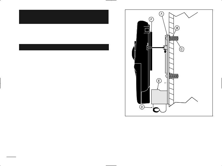
2.Remove the mounting bracket attached to the back of the controller housing by pulling the lower edge of the bracket away and downward from the controller housing.
3.Place the mounting bracket (A) against the wall aligning the top edge at about eye level. Drive three 1" (25 mm) wood screws (B) into the wall through the three holes provided in the bracket.
Note: If you are installing the bracket on drywall or masonry, install screw anchors (C) to prevent screws from loosening.
4.Optional - Insert 3/4" (19 mm) PVC conduit (D) for valve wiring into bracket sleeve (E).
5.Align the slotted openings on the back of controller housing with the mounting bracket tabs. Slide the controller downward to engage the tabs.
6
Note: After installation, store the Quick Reference Guide and the Watering Schedule Form in the pocket (F) behind the controller.
Connecting the Valves
Note: Using 14 to 18 AWG (2.5mm2 to 1mm2) irrigation cable is recommended. This cable is made specifically for automatic irrigation systems and is available in several lengths and conductor count. Always use a cable that has at least one wire for each valve and one wire for the valve common connection.
1.Route the valve control wires between the valves and the controller.
2.Attach the white-color cable wire to one wire from each valve solenoid. (Either solenoid wire can be used for this connection.) This wire is referred to as the valve common.
3.Attach a separate cable wire to the remaining wire from each valve solenoid. Make a note of the wire color code used for each valve and the station it controls. You will need to have this information when connecting the wires to the controller.
4.Secure all wire splices using twist-on wire connectors. To prevent corrosion and possible short circuits, use a grease cap or similar waterproofing method to insulate each connection.
5.Route the wire cable into the controller through the large opening in the base of the housing or through PVC conduit if it is installed. Remove 1/2" (13mm) of insulation from the end of each wire.
Master |
Valve Common |
Station |
Valve |
Wire |
Valves |
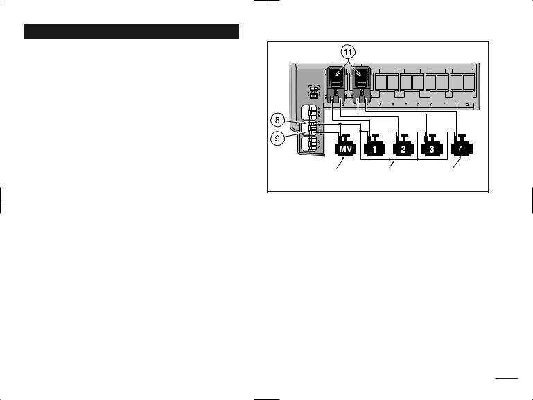
Note: The station module has snap-in wire connectors To attach wires, simply raise the lever and insert the bare wire end into the small hole beneath the lever. Press the lever down to secure the wire. Pull lightly on the wire to confirm that it is locked into the module.
6.Referring to the Controller Components on page 5 and the diagram above, secure the valve common wire to the terminal labeled COM (8). Connect the individual station valve wires to the appropriate station module terminals (11). Connect the master valve control wire (if applicable) to the terminal labeled PUMP/MV (9).
Note: Connecting a master valve or pump start relay is optional and may not be required for your sprinkler system.
7
Connecting a Pump Start Relay
 CAUTION: Never connect an auxiliary pump starter directly to the controller. A 24 VAC relay, rated at 0.50A maximum current draw, must be used to connect the controller to the pump starter circuit.
1.Route a wire pair from the pump start relay into the controller housing.
2.Connect one wire to the valve common COM (8). Connect the remaining wire to the PUMP/MV (9) as shown below.

 Jumper Wire
24 VAC Pump Start Relay Valve Common Wire
 CAUTION: If the pump does not have an automatic pressure control switch, prevent pump damage due to “dead-heading,” by connecting a jumper wire from any unused station terminal to a station terminal with a valve wire connected.
Note: Refer to “Pump Control and Well Recovery” section
8on page 28 for important pump circuit control information.
Connecting the Plug-in Transformer
 CAUTION: Do not plug the transformer into an electrical outlet until all of the wiring procedures have been completed.
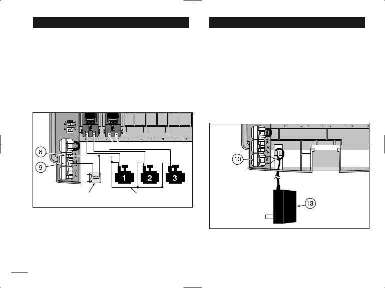
1.Route the cable from the transformer (13) through the small opening provided in the base of the housing. Wrap the cable around and through the restraining post as shown below.
2.Connect one transformer cable wire to each terminal labeled 24 VAC (10). The wires can be connected to either terminal.
Note: The display will begin flashing 12:00 a.m. Press any button to stop the display from flashing.
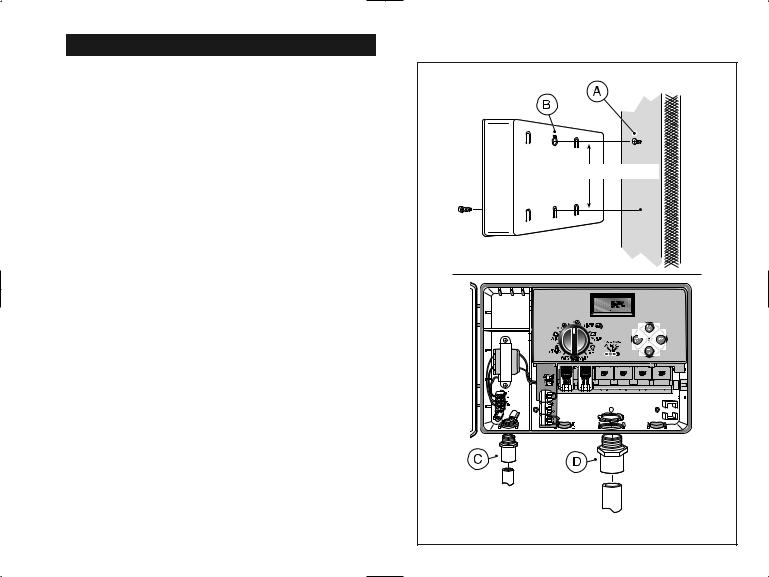
Outdoor Model Installation
Preparing the Cabinet for Installation
1.Remove the lower housing cover (A) by pulling outward on the handle.
2.Remove two phillips screws from the transformer access cover (B). Pull the cover outward from the bottom to remove.
3.Three lower mounting holes (C) are provided. The center hole is open and the outer holes are plugged. If you intend to use the outer holes for installation, carefully drill through the plugs with a 3/16" (5mm) drill bit.
Four wiring access holes are provided in the cabinet base as follows:
(D)- 1/2" (13mm) for power and equipment ground wires.
(E)- 1/2" (13mm) (plugged) for optional Toro Rain Sensor wires.
(F)- 3/4" (19mm) for sprinkler valve wires.
(G)- 1/2" (13mm) (plugged) for optional Toro remote control cable.
4.If planning to install the optional Toro components, remove the plugs as necessary.
9
Installing the Cabinet
1.For safe, reliable operation, select an installation site which will provide the following conditions:
•Protection from irrigation spray, exposure to direct sun during the hottest hours, wind and snow.
•Access to a grounded power source which is not controlled by a light switch or utilized by a high current load appliance, such as a refrigerator or air conditioner.
•Access to the sprinkler control valve wiring and optional accessory wiring.
2.Drive a wood screw (provided) into the wall at eye level (A). Leave the screw extended approximately 1/4" (6.5 mm) from the wall.
Note: If you are installing the controller on drywall or masonry, install screw anchors to prevent screws from loosening. Use the dimension shown to predrill holes for screw anchors.
3.Hang the cabinet on the screw using the keyhole slot (B) on the back panel. Make sure the cabinet slides down securely on the screw.
4.Install the lower mounting screw(s) and tighten securely.
Note: Conduit and adapters are not provided. Install conduit as required by local electrical codes.
5.Install 1/2" (13 mm) conduit (C) for power/equipment ground wires and 3/4" (19 mm) conduit (D) for valve wires.
|
Note: After installation, store the User’s Guide and |
10 |
Quick Reference Guide on the hook located on the |
inside of the door. |
6" (15.24 cm) |
Connecting the Valves
Note: Using 14 to 18 AWG (2.5mm2 to 1mm2) irrigation cable is recommended. This cable is made specifically for automatic irrigation systems and is available in several lengths and conductor count. Always use a cable that has at least one wire for each valve and one wire for the valve common connection.
1.Route the wire cable from the valve location into the controller cabinet.
2.Attach the white (preferably) cable wire to either wire from each valve solenoid. This is called the valve common wire.
Note: The solenoid does not have specific polarity, so either wire can be used for the common wire connection.
3.Connect an individual color-coded cable wire to the remaining solenoid wire of each valve. Make a note the wire insulation color used for each connection and the sprinkler zone controlled by the valve.
 IMPORTANT: To prevent possible short-circuit conditions causing controller damage, properly connect, insulate and waterproof all wire splices.
4.Remove 1/2" (13mm) of insulation from the end of all cable wires to be connected to the controller.
11
8 |
9 |
|
|
|
|
|
|
|
|
|
|
|
|
|
|
Station |
|
|
|
|
|
|
|
|
|
|
|
|
|
|
|
|
|
|
|
|
|
|
|
|
|
|
|
|
|
|
|
|
|
|
|
|
|
|
|
|
|
|
|
|
|
|
|
|
|
|
|
|
|
|
|
|
|
|
|
|
|
|
|
|
|
|
|
||||||||
|
|
|
|
Master |
Valve Common Wire |
|||||||||
|
|
|
|
Valve |
|
|
Valves |
|||||||
|
|
|
|
|
|
|
|
|
|
|
|
|
|
|
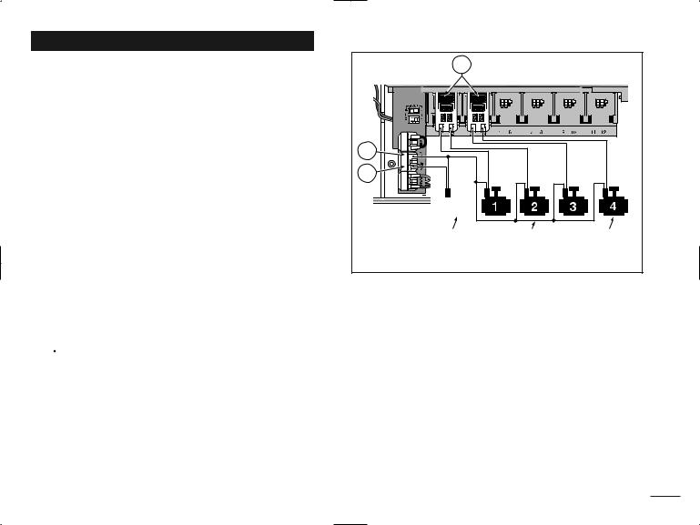
Note: The station module has snap-in wire connectors. To attach wires, simply raise the lever and insert the bare wire end into the small hole beneath the lever. Press the lever down to secure the wire. Pull lightly on the wire to confirm that it is locked into the module.
5.Referring to the Controller Components on page 5 and the diagram above, secure the valve common wire to the terminal labeled COM (8). Connect the individual valve wires to the appropriate expansion module terminals (11). The stations are numbered from left to right, 1 through 12. Connect the master valve wire
(if applicable) to the terminal labeled PUMP/MV (9).
11
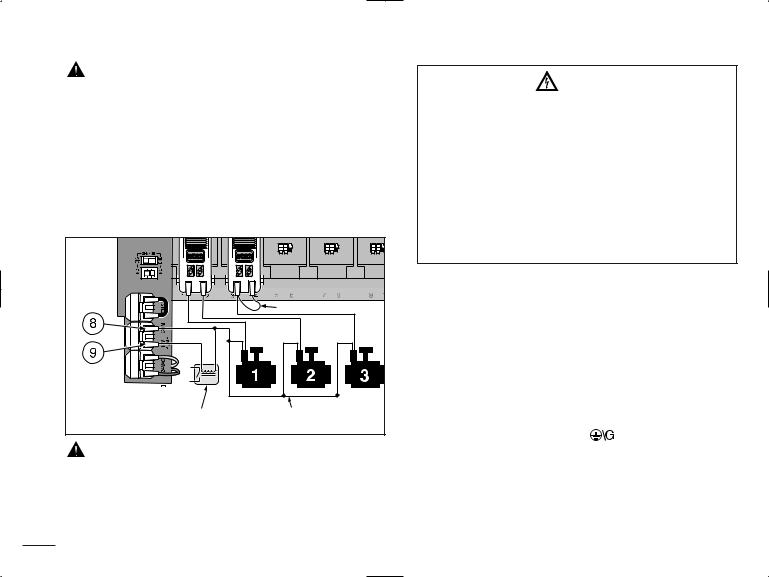
Connecting a Pump Start Relay |
|
Connecting the Power Source |
|
|
|
CAUTION: To prevent controller damage, never |
WARNING |
|||
connect an auxiliary pump starter directly to the |
||||
AC power wiring must be installed and connected |
||||
controller’s 24 VAC output. A 24 VAC 0.50A relay, |
||||
by qualified personnel only. All electrical compo- |
||||
must be used to connect the controller to the pump |
||||
nents and installation procedures must comply |
||||
starter circuit. |
|
|||
|
with all applicable local and national electrical |
|||
1. Route a wire pair from the pump relay into the |
||||
codes. Some codes may require a means of discon- |
||||
controller housing. |
|
|||
|
nection from the AC power source installed in the |
|||
2. Connect one wire to the terminal labeled COM (8). |
||||
fixed wiring and having a contact separation of at |
||||
Connect the remaining wire to the terminal labeled |
||||
least 0.120" (3mm) in the line and neutral poles. |
||||
PUMP/MV (9) as shown below. |
||||
Make sure the power source is OFF prior to con- |
||||
|
|
|||
|
|
necting the controller. |
|
|
|
|
1. Route the power and equipment ground wires from |
||
|
Jumper Wire |
the power source, through the conduit and into the |
||
|
controller transformer compartment. |
|||
|
|
|||
|
|
Note: The controller terminal block accepts wire size |
||
|
|
up to 12 AWG (4 mm2). |
|
|
|
|
2. Remove 3/8" (10 mm) insulation from the wire ends. |
||
|
|
3. Using a small flat blade screwdriver, secure the wires |
||
Pump Start Relay |
Valve Common Wire |
as shown to the terminal block as follows: |
||
Line or Line 1 (L1) to L, Neutral or Line 2 (L2) to N |
||||
|
|
|||
|
|
and Equipment Ground to |
. |
|
CAUTION: To prevent pump damage due to |
4. Install and secure the transformer compartment cover. |
|||
prolonged dead-head pressure, connect a jumper wire |
||||
5. Apply power to the controller. |
|
|||
from an unused station terminal to a terminal with a |
|
|||
Note: The display will begin flashing 12:00 a.m. Press |
||||
with a valve connected. |
|
|||
|
any button to stop the display from flashing. |
|||
Note: Refer to “Pump Control and Well Recovery” section |
||||
|
|
|||
12 on page 28 for important pump circuit control information. |
|
|
||
 Loading...