Toastmaster AM36SS, AM24SS User Manual

Toastmaster®
AM24SS and AM36SS
 ™ Griddles
OWNER'S OPERATING
& INSTALLATION
MANUAL
Toastmaster®
A Middleby Company |
Part No. 37813 |
|
Middleby Cooking Systems Group • 1400 Toastmaster Drive • Elgin, IL 60120 • (847)741-3300 • FAX (847)741-4406 |
Price $15.00 |
|
P Apr. 98 Rev B |

NO QUIBBLE LIMITED WARRANTY
TOASTMASTER, HEREINAFTER REFERRED TO AS THE SELLER, WARRANTS EQUIPMENT MANUFACTURED BY IT TO BE FREE FROM DEFECTS IN MATERIAL AND WORKMANSHIP FOR WHICH IT IS RESPONSIBLE. THE SELLER’S OBLIGATION UNDER THIS WARRANTY SHALL BE LIMITED TO REPLACING OR REPAIRING, AT SELLER’S OPTION, WITHOUT CHARGE, ANY PART FOUND TO BE DEFECTIVE AND ANY LABOR AND MATERIAL EXPENSE INCURRED BY SELLER IN REPLACING OR REPAIRING SUCH PART. SUCH WARRANTY SHALL BE LIMITED TO THE ORIGINAL PURCHASER ONLY AND SHALL BE EFFECTIVE FOR A PERIOD OF ONE YEAR FROM DATE OF ORIGINAL INSTALLATION, OR 18 MONTHS FROM DATE OF PURCHASE, WHICHEVER IS EARLIER; PROVIDED THAT TERMS OF PAYMENT HAVE BEEN FULLY MET.
As part of Toastmaster’s “no quibble” warranty, all in-warranty Toastmaster products that require service, are to be serviced on site.
The warranty period for Accu-Miser griddles shall be 24 months from the date of installation or 30 months from the date of purchase, whichever is earlier.
Normal maintenance functions, including lubrication, cleaning, or customer abuse, are not covered by this “no quibble” warranty.
Seller shall be responsible only for repairs or replacements of defective parts performed by Seller’s authorized service personnel. Authorized service agencies are located in principal cities throughout the contiguous United States, Alaska, and Hawaii. This warranty is valid in the 50 United States and is void elsewhere unless the product is purchased through Middleby International with warranty included.
The foregoing warranty is exclusive and in lieu of all other warranties, expressed or implied. There are no implied warranties of merchantability or of fitness for a particular purpose.
The foregoing shall be Seller’s sole and exclusive obligation and Buyer’s sole and exclusive remedy for any action including breach of contract or negligence. In no event shall Seller be liable for a sum in excess of the purchase price of the item. Seller shall not be liable for any prospective or lost profits of Buyer.
© 1998 Toastmaster, A Middleby Company
 is a registered trademark of Toastmaster, A Middleby Company.
 ™ is a trademark of Toastmaster, A Middleby Company.
Toastmaster • 1400 Toastmaster Dr. • Elgin, IL 60120-9272 • (847) 741-3300 • FAX (847) 741-4406
Middleby Corp 24-Hour Service Hotline 1-800-238-8444
i

WARNING: IN CASE OF FIRE
Disconnect the griddle from its power source IMMEDIATELY. Shutting down the electrical heating elements allows the unit to cool, making it easier to put out the fire.
WARNING: FOR YOUR SAFETY
DO NOT STORE OR USE GASOLINE
OR OTHER FLAMMABLE VAPORS OR LIQUIDS
IN THE VICINITY OF THIS OR ANY OTHER APPLIANCE
CAUTION
Use only a fire extinguisher filled with CO2, which is suitable for electrically powered equipment. Do NOT attempt to fight a grease fire by aiming the nozzle of the fire extinguisher directly at the burning grease. The force will cause the burning grease to be sprayed to adjoining equipment, making it difficult to contain the fire.
CAUTION
Using any parts other than genuine Toastmaster factory parts relieves the manufacturer of all liability.
IMPORTANT
Toastmaster (manufacturer) reserves the right to change specifications and product design without notice. Such revisions do not entitle the buyer to corresponding changes, improvements, additions or replacements for previously purchased equipment.
RETAIN THIS MANUAL FOR FUTURE REFERENCE
This manual provides detailed information for installation and operation of your Accu-Miser griddle. It also contains information to assist the operator in diagnosing problems in the event of a malfunction.
This manual is an important tool for the operator and should be kept readily available.
ii
TABLE OF CONTENTS
SECTION 1 |
|
|
DESCRIPTION............................................................................................................................................... |
1 |
|
A. |
Features............................................................................................................................................. |
1 |
B. |
Component Location.......................................................................................................................... |
1 |
C. |
Specifications..................................................................................................................................... |
2 |
D. |
Electrical Specifications..................................................................................................................... |
2 |
E. |
Dimensional Drawings....................................................................................................................... |
3 |
SECTION 2 |
|
|
INSTALLATION.............................................................................................................................................. |
5 |
|
A. |
Shipping Damage Inspection............................................................................................................. |
5 |
B. |
Unpacking the Griddle....................................................................................................................... |
5 |
C. |
Installation.......................................................................................................................................... |
5 |
D. |
Electrical Connection......................................................................................................................... |
6 |
E. |
Initial Cleaning................................................................................................................................... |
6 |
F. |
Testing the Installation....................................................................................................................... |
6 |
SECTION 3 |
|
|
OPERATION................................................................................................................................................... |
7 |
|
A. |
Controls.............................................................................................................................................. |
7 |
B. |
Seasoning the Griddle....................................................................................................................... |
7 |
C. |
Operating Hints and Safety................................................................................................................ |
7 |
D. |
Daily Operation and Maintenance...................................................................................................... |
8 |
E. |
Troubleshooting................................................................................................................................. |
9 |
SECTION 4 |
|
|
WIRING DIAGRAMS...................................................................................................................................... |
10 |
|
A. |
Wiring Diagram - AM24SS................................................................................................................. |
10 |
B. |
Wiring Diagram - AM36SS................................................................................................................. |
11 |
iii

SECTION 1
DESCRIPTION
A. Features
Models:
•AM24SS, 24” (610mm) wide, two 12” (305mm) infrared heat panels
•AM36SS, 36” (914mm) wide, three 12” (305mm) infrared heat panels
Accu-Miser Series SS griddles are:
•Electrically heated by infrared emitter panels
•Temperature-controlled by solid-state thermostat
•Counter-top mounted
The Accu-Miser griddle employs infrared cooking technology. Infrared heat panels are located below the griddle plate. Each panel is 12” (305mm) in width, and provides uniform heat distribution across its surface.
A thermostatic solid-state controller for each panel accurately maintains the set griddle cooking temperatures for consistent and repeatable results. Each thermostat has a range of 150°F (83°C) to 450°F (232°C).
The individual controls and thermostat allow independent temperature settings for each panel. This feature divides the griddle plate into 12” (305mm)-wide zones that can cook different food products simultaneously.
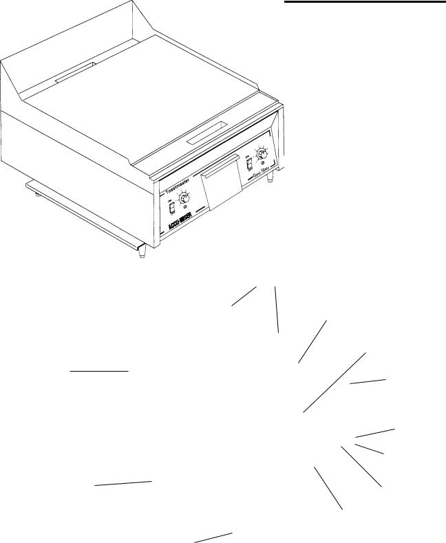
B. Component Location
|
|
Splash Guard |
|
Grease Chute |
|
|
(rear) |
Griddle |
|
|
|
|
|
Plate |
|
|
Grease Chute |
|
|
(front) |
Grease Trough |
|
Grease Trough |
(rear) |
|
(front) |
|
|
Thermostat Control |
|
|
Knob |
|
|
Heating Indicator |
|
|
Light |
Spacer bracket (2) |
|
On/Off Switch |
|
|
|
|
|
Grease Drawer |
4” (102mm) legs (4) (countertop griddles only)
(AM24SS shown)
1
 Loading...