


OPERATING INSTRUCTIONS
DIGITAL VIDEO |
C-DR091 CU Series |
RECORDER |
C-DR161 CU Series |
Thank you for purchasing TOA Digital Video Recorder. Please carefully follow the instructions in this manual to ensure long, trouble-free use of your equipment.

TABLE OF CONTENTS |
|
|
1. |
SAFETY PRECAUTIONS .................................................................................. |
7 |
2. |
HANDLING PRECAUTIONS .......................................................................... |
10 |
|
GENERAL DESCRIPTION |
|
3. |
GLOSSARY OF TERMS .................................................................................. |
11 |
4. |
GENERAL DESCRIPTION ............................................................................. |
12 |
5. |
MODEL NUMBER CONFIGURATION ........................................................ |
12 |
6. |
FEATURES .......................................................................................................... |
12 |
2
12.4. Auto-Recording Settings .................................................................................. |
29 |
|
|
12.4.1. Schedule setting .................................................................................. |
29 |
|
12.4.2. Setting the group .................................................................................. |
30 |
|
12.4.3. Other settings ....................................................................................... |
30 |
13. MONITOR DISPLAY |
|
|
13.1. Monitor Switch ................................................................................................. |
31 |
|
13.2. About Live and Playback Modes ...................................................................... |
31 |
|
13.3. Display When In Live Mode ............................................................................. |
32 |
|
13.4. Display During Playback .................................................................................. |
33 |
|
13.5. FullScreen Display ......................................................................................... |
33 |
|
13.6. Multi-Segment SplitScreen Display ............................................................... |
34 |
|
13.7. Sequence Display ............................................................................................ |
35 |
|
13.8. Zoom Display ................................................................................................... |
35 |
|
14. OTHER FUNCTIONS |
|
|
14.1. |
Triplex Display ................................................................................................. |
36 |
14.2. |
Position Setting Display ................................................................................... |
37 |
15. RECORDING |
|
|
15.1. Before Recording ............................................................................................. |
38 |
|
|
15.1.1. Disk mode ............................................................................................ |
38 |
|
15.1.2. Recording order to hard disks .............................................................. |
38 |
|
15.1.3. Disk recording mode ............................................................................ |
39 |
15.2. Recording Mode ............................................................................................... |
39 |
|
15.3. |
Priority Recording ............................................................................................ |
39 |
|
15.3.1. How to perform priority recording ......................................................... |
39 |
15.4. Auto Recording (Alarm Event Recording and Normal Recording) ................... |
40 |
|
|
15.4.1. Alarm event recording .......................................................................... |
40 |
|
15.4.2. Normal recording ................................................................................. |
41 |
15.5. Pre-Recording .................................................................................................. |
41 |
|
15.6. Recording State ............................................................................................... |
41 |
|
15.7. Recording Operation When Edge/Level Settings Are Performed .................... |
43 |
|
15.8. |
Picture Quality .................................................................................................. |
43 |
15.9. Recording Rate ................................................................................................ |
44 |
|
15.10. Recording time ................................................................................................. |
44 |
|
15.11. Available Disk Time and Operation .................................................................. |
44 |
|
16. PLAYBACK |
|
|
16.1. Type of Playback ............................................................................................. |
45 |
|
16.2. How to Perform Playback ................................................................................ |
45 |
|
|
16.2.1. Playback .............................................................................................. |
45 |
|
16.2.2. Reverse playback ................................................................................ |
45 |
|
16.2.3. Playback stop ....................................................................................... |
45 |
|
16.2.4. Earliest image display .......................................................................... |
46 |
|
16.2.5. Latest image reverse playback ............................................................ |
46 |
|
16.2.6. Fast forward/reverse playback ............................................................. |
46 |
|
16.2.7. Pause ................................................................................................... |
46 |
|
16.2.8. Frame advance/frame reverse playback .............................................. |
46 |
16.3. Event ................................................................................................................ |
47 |
|
|
16.3.1. Instance event access ......................................................................... |
47 |
3
17. SEARCH |
|
17.1. Date/Time Search ............................................................................................ |
48 |
17.2. Event Search ................................................................................................... |
49 |
17.2.1. Event search list display ...................................................................... |
50 |
18. ARCHIVE .............................................................................................................. |
51 |
18.1. Archiving & Transfer Times .............................................................................. |
52 |
18.2. Archiving by Entering the Date and Time ........................................................ |
53 |
18.3. Archiving from the Playback Screen ................................................................ |
54 |
18.4. Display During Archiving .................................................................................. |
55 |
18.4.1. Display during archiving ....................................................................... |
55 |
18.4.2. Archiving stop ...................................................................................... |
55 |
18.4.3. Archiving completion ............................................................................ |
55 |
18.4.4. About error messages .......................................................................... |
56 |
18.5. When Viewing Saved Data .............................................................................. |
57 |
18.5.1. PC Operating conditions and image data ............................................ |
57 |
18.5.2. Folder Configuration and File Name .................................................... |
57 |
18.5.3. Playback by way of viewer software .................................................... |
58 |
18.5.4. Tampering/alteration check .................................................................. |
59 |
19. ABOUT SECURITY SETTING |
|
19.1. Securing the Digital Video Recorder's Operating Keys .................................... |
60 |
19.1.1. Password and operation levels ............................................................ |
61 |
19.2. Security Settings Using a USB Key ................................................................. |
62 |
19.2.1. USB Key Level Settings and Operation Levels .................................... |
62 |
19.2.2. USB Key registration ............................................................................ |
62 |
19.2.3. Resetting the USB Key registration ..................................................... |
63 |
19.3. Login and Logout by Password ........................................................................ |
63 |
19.3.1. Password Entry .................................................................................... |
63 |
19.3.2. When USB key settings are invalid... ................................................... |
63 |
19.3.3. When USB key settings are valid... ...................................................... |
64 |
19.4. Security Settings Against Remote External Access ......................................... |
65 |
19.5. Security Settings Against Web Access ............................................................ |
65 |
20. MALFUNCTION OPERATION |
|
20.1. Stopping the Buzzer ......................................................................................... |
66 |
20.2. Hard Disk Errors .............................................................................................. |
66 |
20.2.1. "Playback stopped" warning display .................................................... |
66 |
20.2.2. "Restart" warning display ..................................................................... |
67 |
20.2.3. Checking hard disks when an error has occurred ................................ |
67 |
20.2.4. If a hard disk error occurs .................................................................... |
67 |
20.3. Video Loss ....................................................................................................... |
68 |
20.3.1. If video loss occurs... ........................................................................... |
68 |
20.4. Fan Malfunction ............................................................................................... |
69 |
20.4.1. If a fan malfunction occurs.... ............................................................... |
69 |
20.5. "Hard Disk Full" Warning ................................................................................. |
69 |
20.5.1. If the hard disk becomes full.... ............................................................ |
69 |
20.6. Operation Following Restoration From a Power Outage ................................. |
70 |
20.6.1. Monitor display ..................................................................................... |
70 |
20.6.2. Recording ............................................................................................. |
70 |
4

SETTINGS |
|
21. SETTING PROCEDURES AND ITEM LIST |
|
21.1. Basic Setting Procedures ................................................................................. |
71 |
21.2. Setting Item List ............................................................................................... |
72 |
22. MAIN MENU SETTING |
|
22.1. About the Main Menu Setting ........................................................................... |
74 |
22.1.1. Saving setting ...................................................................................... |
75 |
22.1.2. Implementing setting ............................................................................ |
75 |
23. RECORDING SETTING ................................................................................... |
76 |
23.1. Priority Recording Setting ................................................................................ |
77 |
23.1.1. Recording setting ................................................................................. |
78 |
23.2. Auto Recording Setting .................................................................................... |
79 |
23.2.1. Schedule .............................................................................................. |
79 |
23.2.2. Setting of groups A-F .......................................................................... |
80 |
23.2.3. Special day setting ............................................................................... |
83 |
23.2.4. Motion detection settings ..................................................................... |
84 |
23.3. Pre-Recording Settings .................................................................................... |
85 |
24. SCREEN DISPLAY SETTING ........................................................................ |
86 |
24.1. Character Display Settings .............................................................................. |
87 |
24.2. Monitor Output Setting ..................................................................................... |
88 |
24.3. Sequence Setting ............................................................................................. |
88 |
24.4. Camera Name Setting ..................................................................................... |
89 |
24.5. DVR Name Setting ........................................................................................... |
89 |
25. NETWORK SETTING ....................................................................................... |
90 |
26. MAIL SETTING ................................................................................................... |
91 |
26.1. Transmission Condition Setting ....................................................................... |
92 |
27. SYSTEM SETTING ............................................................................................ |
93 |
27.1. I/O Terminal Mode Setting ............................................................................... |
94 |
27.2. Control Output Terminal Setting ...................................................................... |
95 |
27.3. Security Setting ................................................................................................ |
96 |
27.4. Camera Preset Pattern Setting ........................................................................ |
97 |
28. LOG DISPLAY |
|
28.1. Recording Log .................................................................................................. |
98 |
28.2. Failure Log ....................................................................................................... |
99 |
28.3. System Log ...................................................................................................... |
99 |
29. DATE/TIME SETTING .................................................................................... |
100 |
30. EQUIPMENT MAINTENANCE .................................................................... |
101 |
30.1. Hard Disk Drive Initialization .......................................................................... |
102 |
5

WEB FUNCTIONS |
|
31. WEB SERVER FUNCTIONS |
|
31.1. About the Functions ....................................................................................... |
103 |
31.2. System Requirements .................................................................................... |
103 |
31.3. How to Log In ................................................................................................. |
104 |
31.3.1. Access inhibit ..................................................................................... |
104 |
31.4. Top Page ....................................................................................................... |
105 |
31.4.1. For administrator account .................................................................. |
105 |
31.4.2. For user account ................................................................................ |
105 |
31.5. Menu Screen .................................................................................................. |
106 |
31.5.1. Menu screen setting ........................................................................... |
106 |
31.6. Live Image Transmission ............................................................................... |
107 |
31.6.1. For administrator account .................................................................. |
107 |
31.6.2. For user account ................................................................................ |
107 |
31.6.3. Screen change button ........................................................................ |
108 |
31.6.4. Camera control section ...................................................................... |
108 |
31.7. Playback Transmission .................................................................................. |
110 |
31.7.1. Playback Operations .......................................................................... |
111 |
31.7.2. Searching ........................................................................................... |
111 |
31.7.3. Download ........................................................................................... |
112 |
31.7.4. Duplex display .................................................................................... |
113 |
31.8. Remote control ............................................................................................... |
114 |
31.9. Web Indication setting .................................................................................... |
115 |
ADDITIONAL INFORMATION |
|
32. RECORDING TIME TABLE |
|
32.1. About Picture Quality Settings During Recording .......................................... |
116 |
33. TROUBLESHOOTING ................................................................................... |
119 |
34. INDEX................................................................................................................... |
121 |
35. SPECIFICATIONS ........................................................................................... |
127 |
6

1. SAFETY PRECAUTIONS
•Before installation or use, be sure to carefully read all the instructions in this section for correct and safe operation.
•Make sure to observe the instructions in this manual as the conventions of safety symbols and messages regarded as very important precautions are included.
•We also recommend you keep this instruction manual handy for future reference.
Safety Symbol and Message Conventions
Safety symbols and messages described below are used in this manual to prevent bodily injury and property damage which could result from mishandling. Before operating your product, read this manual first and understand the safety symbols and messages so you are thoroughly aware of the potential safety hazards.
 WARNING
 WARNING
When Installing the Unit
Do not expose the unit to rain or an environment where it may be splashed by water or other liquids, as doing so may result in fire or electric shock.
Indicates a potentially hazardous situation which, if mishandled, could result in death or serious personal injury.
•This is a class A product. In a domestic environment this product may cause radio interference in which case the user may be required to take adequate measures.
•Use the unit only with the voltage specified on the unit. Using a voltage higher than that which is specified may result in fire or electric shock.
•Do not cut, kink, otherwise damage nor modify the power supply cord. In addition, avoid using the power cord in close proximity to heaters, and never place heavy objects -- including the unit itself -- on the power cord, as doing so may result in fire or electric shock.
•Avoid installing or mounting the unit in unstable locations, such as on a rickety table or a slanted surface. Doing so may result in the unit falling down and causing personal injury and/or property damage.
When the Unit is in Use
•If any of the following irregularities occurs, immediately switch off the power, disconnect the power supply plug from the AC outlet and inform the shop from where the unit was purchased. Further using the unit may result in fire or electric shock.
·If you detect smoke or a strange smell coming from the unit
·If water or any metallic object gets into the unit
·If the unit falls, or the unit case breaks
·If the power supply cord is damaged (exposure of the core, disconnection, etc.)
·If no image appears
•To prevent a fire or electric shock, never open the unit case nor modify the unit as there are high voltage components inside the unit. Refer all servicing to your nearest TOA dealer.
•Do not place cups, bowls, or other containers of liquid or metallic objects on top of the unit. If they accidentally spill into the unit, this may cause a fire or electric shock.
•Do not insert nor drop metallic objects or flammable materials in the ventilation slots of the unit's cover, as this may result in fire or electric shock.
•Do not touch the power supply plug or control line during thunder and lightning, as this may result in electric shock.
7

CAUTION |
Indicates a potentially hazardous situation which, if mishandled, could |
result in moderate or minor personal injury, and/or property damage. |
When Installing the Unit
•Never plug in nor remove the power supply plug with wet hands, as doing so may cause electric shock.
•When unplugging the power supply cord, be sure to grasp the power supply plug; never pull on the cord itself. Operating the unit with a damaged power supply cord may cause a fire or electric shock. When removing the power cord, be sure to hold its plug to pull.
•When moving the unit, be sure to remove its power supply cord from the wall outlet. Moving the unit with the power supply cord connected to the outlet may cause damage to the power supply cord, resulting in fire or electric shock.
•Do not block the ventilation slots in the unit's cover. Doing so may cause heat to build up inside the unit and result in fire.
•Avoid installing the unit in humid or dusty locations, in locations exposed to the direct sunlight, near the heaters, or in locations generating sooty smoke or steam as doing otherwise may result in fire or electric shock.
•Do not connect a network terminal exposed to excessive voltage to the 100BASE-TX terminal, Hard disk expansion unit connection terminal or Remote control I/O terminal A, as doing so may result in fire or electric shock.
When the Unit is in Use
•Do not place heavy objects on the unit as this may cause it to fall or break which may result in personal injury and/or property damage. In addition, the object itself may fall off and cause injury and/or damage.
•Clean the unit periodically. Contact your TOA dealer regarding the cleaning. If dust is allowed to accumulate in the unit over a long period of time, a fire may result.
•If dust accumulates on the power supply plug or in the wall AC outlet, a fire may result. Clean it periodically. In addition, insert the plug in the wall outlet securely.
•Switch off the power, and disconnect the power supply plug from the AC outlet when cleaning or leaving the unit unused for long periods of time. Doing otherwise may cause a fire or electric shock.
The equipment must be connected to an earthed mains socket-outlet.
-Finland
"Laite on liitettävä suojamaadoituskoskettimilla varustettuun pistorasiaan"
-Norway
"Apparatet må tilkoples jordet stikkontakt"
-Sweden
"Apparaten skall anslutas till jordat uttag"
8

CU version complies with Part 15 of the FCC Rules.
Note
This equipment has been tested and found to comply with the limits for a Class A digital device, pursuant to Part 15 of the FCC Rules. These limits are designed to provide reasonable protection against harmful interference when the equipment is operated in a commercial environment. This equipment generates, uses, and can radiate radio frequency energy and, if not installed and used in accordance with the instruction manual, may cause harmful interference to radio communications. Operation of this equipment in a residential area is likely to cause harmful interference in which case the user will be required to correct the interference at his own expense.
Modifications
Any modifications made to this device that are not approved by TOA Corporation may void the authority granted to the user by the FCC to operate this equipment.
This equipment is classified as a LASER CLASS 1 PRODUCT. The following classification label is located on the drive.
CLASS 1 LASER PRODUCT
CAUTION:
INVISIBLE LASER RADIATION WHEN OPEN.
AVOID EXPOSURE TO BEAM.
9
2. HANDLING PRECAUTIONS
•The supplied power supply cord is designed for exclusive use with the Digital Video Recorder. Never use it with other equipment.
•Do not connect the10BASE-T/100BASE-TX terminal, Hard disk expansion unit connection terminal or Remote control I/O terminal A to networks that could be exposed to excessive electrical voltage. Failure to follow this instruction could result in electric shock or fire.
•It is recommended that the Recorder be always used in locations where the ambient temperature ranges from +5°C to +40°C (41°F to 104°F) and humidity levels of less than 80% to ensure that no condensation is formed.
•When moving the Recorder, first disconnect its power supply plug from the AC outlet and then wait at least 30 seconds before moving.
•Avoid moving the Recorder suddenly from a cold location to a warm location, or installing it in close proximity to an air-conditioner outlet, as internal condensation could result. When condensation occurs, do not switch on the power until the Recorder has sufficiently dried. Also, when brought into a warm room from the cold outdoors, be sure to leave it unused for at least half a day before using it.
•Avoid installing the Recorder in humid or dusty locations, or in locations exposed to direct sunlight, sooty smoke or steam. Note that even in locations which are not particularly dusty, dust may accumulate at the Recorder’s ventilation slots. Because this could cause an extreme rise in temperature inside the Recorder, be sure to clean the ventilation slots periodically after switching off the power and disconnecting the power supply plug from the AC outlet. It is highly recommended that the ventilation slots be cleaned once a year.
•When cleaning the Recorder, be sure to switch off the power. Wipe with a soft dry cloth. If it gets very dirty, use the soft cloth slightly moistened in neutral cleanser. Never use volatile spirits like thinner, benzine, or alcohol. Such chemicals may damage its plastic surface.
•Do not block the ventilation slots or cooling fan, which could cause the temperature inside the Recorder to rise, possibly resulting in unit failure. Install the Recorder at least 100 mm (3.9 inch) away from the nearest wall surface.
•Since the Recorder is equipped with a cooling fan, a motor sound is generated. Avoid installing the Digital Video Recorder in locations which resonate electrical motor noise.
•Do not install the Recorder in locations influenced by strong electrical or magnetic fields, as monitor screen pictures may become distorted or the Recorder could fail.
•The Recorder can be used only in a commercial and industrial area. Operation of this equipment in a residential area is likely to cause radio disturbance and TV interference.
•Avoid jarring or striking the Recorder. The Recorder is a piece of precision equipment and accidentally dropping it or subjecting it to strong impacts could cause its failure. When transporting the Recorder, carefully pack it in the supplied carton to protect it from shock.
•Avoid using the Recorder in locations exposed to vibration. The Recorder is a piece of precision equipment, as this may cause the unit malfunction.
•Avoid installing the Recorder vertically or tilting it at extreme angles, since it is designed to be used in a horizontal position only.
•About the hard disks
•If the hard disk fails, recorded data cannot be restored.
•Save important recordings to DVD-R/RW disks.
•Recordings copied from video images or video recordings with registered copyrights may not be used for commercial purposes other than for private use without express permission from the copyright holder.
10
•TOA takes no responsibility for any incidental damage, such as loss of sales opportunities, that may result.
•Avoid using the camera in line-locked mode. Failure to do so may cause the displayed camera images to flicker. Also, video may be lost if power frequency fluctuates significantly.
3. GLOSSARY OF TERMS
Triplex
This function permits recording while viewing live and recorded images in multi-screen display. In Triplex setting, individual live or recorded images can be set to be displayed on individual split-screen segments.
Pre-Recording
Retroactive recordings can be made for up to 5 minutes before the occurrence of an alarm event (alarm signal input or motion movement) or priority recording, even if no recording is currently in progress.
Mirror Recording
Recording can be simultaneously made on 2 hard disks. Even if one hard disk should fail, the other hard disk continues to record or play back.
Master and Slave Units
When synchronizing the Digital Video Recorders, one can be designated as a master unit, which can be used to control the other slave units.
Normal Mode
When the first hard disk finishes recording, the second hard disk automatically begins to record. When the settings (recording rate and picture quality) of both normal and mirror modes are set to be identical, the recording time for normal mode is twice that of mirror mode.
Alarm Event Recording
Refers to both alarm recording and motion detected recording. Alarm recording is performed when the alarm input terminal of the Digital Video Recorder or Combination Camera receives a signal. Motion detected recording begins when movement is detected in the camera image.
Recording Rate (IPS)
Refers to the number of image frames to be recorded per second. The unit is IPS. The larger IPS value is, the shorter recording intervals can become.
Event
Recording data from the start to the end of recording mode (Priority recording, Alarm Event recording and Normal recording) is expressed as one event.
Post time
Set the time until the hard disk finished recording.
Schedule
The Digital Video Recorder’s auto-recording mode allows recording to be made according to a preset schedule.
Live mode
Mode displaying current live camera images.
Playback mode
Mode displaying recorded camera images.
11

4. GENERAL DESCRIPTION
TOA's C-DR Series Digital Video Recorders feature a digital compression method that permits camera images to be recorded on an internal hard disk. The C-DR091 Series is designed for 9 channels, while the C-DR161 Series can be used for up to 16 channels.
It can simultaneously play back recorded camera images while continuing to record images onto the hard disk.
Mounting in EIA-Standard equipment racks can also be easily performed with the addition of optional rack mounting brackets.
5. MODEL NUMBER CONFIGURATION
A total of 16 type variations are available depending on the combination of hard disk capacity and DVD drive availability.
For model numbers and hard disk capacity, please refer to the following table.
C - D R 1 6 1 D 0 8 |
|
|
9 channels |
16 channels |
Hard disk capacity |
|||||||||||
|
|
|
|
|
|
|
|
|
|
|
|
|
|
|||
|
|
|
|
|
|
|
|
|
|
|
08 |
: 80 GB |
|
C-DR091D08 |
C-DR161D08 |
80 GB × 1 |
|
|
|
|
|
|
|
||||||||||
|
|
|
|
|
|
1 |
: 160 GB |
|
C-DR091-08 |
C-DR161-08 |
80 GB × 1 |
|||||
|
|
|
|
|
|
|
|
|
|
|
3 |
: 320 GB |
|
|||
|
|
|
|
|
|
|
C-DR091D1 |
C-DR161D1 |
160 GB × 1 |
|||||||
|
|
|
6 |
: 600 GB |
|
|||||||||||
|
|
|
|
|
|
|
|
|
|
|
|
|
|
C-DR091-1 |
C-DR161-1 |
160 GB × 1 |
|
|
|
|
|
|
|
|
|
|
|
|
|
|
|||
|
|
|
|
|
|
|
|
|
|
|
D : With DVD |
|
C-DR091D3 |
C-DR161D3 |
160 GB × 2 |
|
|
|
|
|
|
|
|
|
|
|
|
||||||
|
|
|
|
|
|
|
|
|
|
|
- : Without DVD |
|
||||
|
|
|
|
|
|
|
|
|
|
|
|
C-DR091-3 |
C-DR161-3 |
160 GB × 2 |
||
|
|
|
|
|
|
|
|
|
|
|
|
|
|
|||
|
|
|
|
|
|
|
|
|
|
|
|
|
|
|||
|
|
|
|
|
|
|
|
|
|
|
|
|
|
C-DR091D6 |
C-DR161D6 |
300 GB × 2 |
|
|
|
|
|
|
|
|
|
|
|
09 |
: for 9 channels |
|
|||
|
|
|
|
|||||||||||||
|
16 |
: for 16 channels |
|
C-DR091-6 |
C-DR161-6 |
300 GB × 2 |
||||||||||
6. FEATURES
•Simultaneous Recording/Playback Function
Recorded images can be played back without interrupting recording.
•Triplex (Recording + Playback + Live Image) Function
Live and recorded images can be simultaneously viewed during recording in multi-screen display.
•Pre-Recording
Retroactive recordings can be made for up to 5 minutes before the occurrence of an alarm event (alarm signal input or motion movement) or priority recording, even if no recording is currently in progress.
•Speed Search Function
Date/time Search and Event Search functions permit desired scenes to be quickly found and viewed.
•Mirroring Recording
Mirroring Recording function performs the simultaneous recording of data onto the two hard disks. Even if one of the disks fails, recording and playback can still be performed using the other disk. For models with a single hard disk (versions with model number suffix -08, -1, D08 or D1), the mirror mode is available only when the hard disk expansion unit is connected.
The possibility of data loss due to hard disk failure is greatly reduced, increasing reliability.
12
•High Picture Quality and High Frame Rate
Recording and playback can be simultaneously performed at a maximum of 120 IPS. (Image compression method: Motion-JPEG.) Picture quality can be adjusted in five levels, allowing high quality recording or extended recording according to the intended purpose of use. Picture quality and recording intervals can be freely set for individual cameras and recording system.
•Auto-recording
The Digital Video Recorder starts recording shortly after power on and makes recordings by preset schedule. The auto-recording function permits Normal recording and Alarm event recording, for each of which different setting can be performed. (Refer to p. 79; Auto-recording setting.)
•Network Function
Use this function to remotely monitor or control cameras connected to the Digital Video Recorder, or search or play back their recorded images on a PC web browser.
•Email Function
Email can be transmitted when an alarm event or failure occurs. Up to 4 destination addresses can be programmed.
•Cascade Connections
Cascade-connecting 8 Digital Video Recorders permits camera images of up to 128 cameras to be viewed on a single monitor display. Up to 4 C-RM1000 Remote Controllers can be connected in a system, allowing each controller to control all Digital Video Recorders and Combination Cameras. (Refer to p. 20; Connections.)
•Archive Function
Recorded images can be copied onto the DVD-R/RW (available to model with DVD) or to the USB memory. Viewer software is also downloaded at the same time. (Refer to p. 51; Archive.)
•Security Function
Two security settings, using a password and USB key lock, are made available. The use of both methods ensures the highest security. (Refer to p. 60; About security setting.)
•Hard disk expansion
Up to 2 Hard Disk Expansion units of C-DA1000-1 (1.2 TB) and/or C-DA1000-2 (2.4 TB) can be connected per Digital Video Recorder. UP to 4.8 TB can be added to the Digital Video Recorder’s hard disk capacity.
13
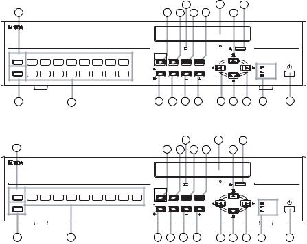
7. NOMENCLATURE AND FUNCTIONS
[ C-DR161 Series Front ]
18 |
19 |
20 |
2 |
|
|
|
|
|
|
|
|
|
5 |
7 |
9 |
11 |
14 |
|
|
|
|
|
|
|
|
|
|
|
|
DVD |
|
|
ARCHIVE |
1 |
2 |
3 |
4 |
5 |
6 |
7 |
8 |
PRIORITY |
BUZZER STOP/ |
|
|
MENU/ |
|
REC |
ALARM RESET |
|
SEARCH |
ENTER |
|
|||||||||
KEY LOCK |
9 |
10 |
11 |
12 |
13 |
14 |
15 |
16 |
|
|
|
MULTI |
|
REC |
MONITOR 1 |
ZOOM |
|
SCREEN |
SEQUENCE |
||||||||||
|
|
|
|
|
|
|
|
|
|
|
|
|
|
FAILURE |
|
|
|
|
|
|
|
|
|
|
|
|
|
|
HD FULL |
MONITOR 2
DIGITAL VIDEO RECORDER C-DR161
3 |
4 |
6 |
8 |
10 |
12 |
13 |
15 |
16 |
17 |
1 |
[ C-DR091 Series Front ]
2 |
|
|
|
|
|
|
|
|
|
|
|
18 |
|
19 |
20 |
|
|
|
|
|
|
|
|
|
|
5 |
7 |
9 |
11 |
14 |
|
|
|
|
|
|
|
|
|
|
|
|
|
DVD |
|
|
|
ARCHIVE |
1 |
2 |
3 |
4 |
5 |
6 |
7 |
8 |
9 |
PRIORITY |
BUZZER STOP/ |
|
|
MENU/ |
|
REC |
ALARM RESET |
SEARCH |
|
ENTER |
|
KEY LOCK |
|
|
MULTI |
|
REC |
MONITOR 1 |
ZOOM |
SCREEN |
SEQUENCE |
||
|
|
|
|
|
FAILURE |
|
|
|
|
|
HD FULL |
|
MONITOR 2 |
|
|
|
|
|
|
|
|
|
DIGITAL VIDEO RECORDER C-DR091 |
3 4 6 8 10 12 13 15 16 17 1
(1)Power key [  ]
]
Pressing the Power key changes the Digital Video Recorder's mode from standby to operation mode. To switch from operation mode to standby mode, hold down the Power key for 2 seconds or more. (Refer to p. 26; Digital Video Recorder Activation and Termination.)
(2)Archive Terminal
Use this terminal when copying video data recorded on a hard disk to a USB memory. (Refer to p. 51; Archive.)
(3)Key lock terminal
Insert the preprogrammed USB key into this terminal to cancel the security lock setting. (Refer to p. 60; Securing the Digital Video Recorder's Operating Keys.)
(4)Camera selector key
Selects cameras displayed on the live or playback screens. Pressing the Camera selector key displays the corresponding camera image on the full screen.
(5)Priority recording key
Used to start priority recording. To stop priority recording, hold down the Priority recording key for 2 seconds or more. The Priority recording key flashes red during priority recording. (Refer to p. 39; Priority Recording.)
(6)Monitor key
Use this key when switching operation between Monitor 1 and Monitor 2 outputs.
This key lights when pressed, and extinguishes when pressed again. Monitor 1 output is enabled when the key is unlit, and Monitor 2 output is enabled when the key is lit. Monitor 2 output can be operated with the Camera selector keys, Multi-screen key, and Sequence key. (Refer to p. 31; Monitor display.)
(7)Buzzer stop key (Alarm reset key)
When priority recording, equipment failure, or alarm event recording takes place, a buzzer sounds. Pressing this key disables the buzzer. Use this key to reset alarm event recording. Hold down this key for 2 seconds or more to reset alarm event recording.
(8)Zoom key
Use the Zoom key to zoom in on the live and playback screens (2x zoom). If this key is pressed during full-screen display, the cursor for determining the zoom position is displayed. If the zoom position is confirmed and the Menu key is pressed, the 2X zoomed screen is displayed. Pressing this key again cancels the zoom mode. (Refer to p. 35; Zoom Display.)
14

(9)Search key
Use this key to search for recorded images. If the Search key is pressed when the live or playback screen is displayed, the search screen
is displayed. To exit the search screen, press the [ ] key. (Refer to p. 48; Search.)
(10)Multi-Screen / [-] Key
•Multi-screen display
Displays live or recorded camera images on the multi-segment split screen. The screen switches to 4-segment, 9-segment and 16segment split screen displays with each depression of this key. (Refer to p. 34; MultiSegment Split-Screen Display.)
•Reverse setting value selection [-]
Pressing this key while setting values are selected on the menu screen varies setting values in the reverse direction.
•Triplex setting screen activation
If the Multi-Screen key is continuously pressed for 2 seconds or more while the multi-segment split screen is displayed, the Triplex setting screen is displayed. To exit the Setting screen, hold down the Menu key for 2 seconds or more. (Refer to p. 36; Triplex display.)
•Position setting screen activation
If the Multi-screen key is continuously pressed for 2 seconds or more while multi-split screen is displayed in the Live mode, the Position setting screen is displayed. To exit the Setting screen, hold down the Menu key for 2 seconds or more. (Refer to p. 37; Position setting display.)
(11)Menu key
•Activating the Menu screen
Holding down the Menu key for 2 seconds or more when the Monitor key remains unlit
displays the menu screen on the Monitor 1 screen. To return to live mode, press the [ ] key. (Refer to p. 74; Main menu setting.)
•Menu item confirmation
Use this key when confirming selected setting items on the menu screen, such as "Yes," "No" or "Execute." (Refer to p. 74; Main menu setting.)
•Advancing to the next menu setting screen
Press this key when advancing from the position indicated by the  mark on the menu setting screen to the next menu setting screen. (Refer to p. 74; Main menu setting.)
•Exiting the motion setting screen
Hold down the Menu key for 2 seconds or more to exit the motion detection setting on the menu screen. (Refer to p. 84; Motion detection settings.)
•Activating the Password entry screen
Holding down the Menu key for 2 seconds or more when the Security setting is activated displays the Password entry screen. (Refer to p. 96; Security setting.)
(12)Sequence/ [ + ] Key
•Sequence
Pressing the Sequence key in live mode causes the camera outputs to be displayed in preprogrammed sequential order. (Refer to p. 35; Sequence Display.)
•Forwarding [+] the setting value
Pressing the setting value on the Menu screen during selection changes the setting value in forward direction.
(13)Reverse playback [ ] key
] key
•Reverse playback
Images are played back in reverse if the Reverse playback key is pressed. (Refer to p. 45; Playback.)
•Moving the cursor to the left on the menu screen
Use this key to move the cursor to the left on the menu screen.
•Returning the Menu screen to the previous
screen
Pressing the [  ] key when the cursor positions to the left on the Menu screen returns the display to the previous screen.
•Returning to the live mode
Pressing the [ ] key on the Menu screen returns the display to the live mode.
(14)Pause [  ,
,  ] key
] key
•Pause of playback/reverse playback screens
Use this key to temporarily stop the playback display. Operation can be performed for the archive menu display, frame advance/reverse playback, and instant event access playback while the display is temporarily stopped. (Refer to p. 51; Archive.) (Refer to p. 45; Playback.)
•Moving the cursor upward on the Menu screen
Used this key to move the cursor upward on the Menu screen.
(15)Stop [ 
 ,
,  ] key
] key
•Stop of playback/reverse playback
Use this key to stop playback or reverse playback. (Refer to p. 45; Playback.)
Note
Recording does not stop even if the Stop key is pressed.
15
•Moving the cursor downward on the Menu screen
Use this key to move the cursor downward on the Menu screen.
(16)Playback [  ] key
] key
Pressing the Playback key plays back recorded images. (Refer to p. 45; Playback.)
•Moving the cursor to the right on the Menu screen
Use this key to move the cursor to the right on the Menu screen.
(17)Informational Indicator
•Recording indicator
Lights during recording (Priority recording, Normal recording, Alarm Event recording)
•Failure indicator
Flashes when video is lost or when a fan or hard disk failure occurs. Refer to the failure log on the menu screen for the cause of each equipment failure. The LED flashes until the Recorder returns to normal state.
•Available hard disk space indicator
Flashes when the available disk space falls below the specified warning level while in write protect mode and when the available disk spaces runs out of time. This indicator does not light (flash) while in overwrite mode.
(Refer to p. 93; System setting.)
(18)DVD indicator
Flashes when the DVD-R/RW is inserted and while the inserted disk is being recognized, and continuously lights while the disk is being written.
(19)DVD receptacle
Place a DVD-R/RW here when copying data recorded on the Digital Video Recorder.
(20)DVD eject Key
Use this key to insert or eject a DVD-R/RW.
16
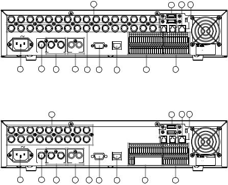
[C-DR161 series Rear]
25 |
31 |
32 |
33 |
|
|
|
|
|
|
|
|
|
|
|
|
|
|
|
|
|
|
|
RM |
|
|
|
|
|
|
|
|
|
|
|
|
|
|
|
|
IN |
|
|
TERMINATION |
|
|
|
|
|
|
|
|
|
|
|
|
|
|
|
|
|
|
|
ON |
|
|
|
|
|
|
|
|
|
|
|
|
|
|
|
|
|
|
|
OFF |
1 |
2 |
3 |
4 |
5 |
6 |
7 |
8 |
9 |
10 |
11 |
12 |
13 |
14 |
15 |
16 |
1 |
DISK ARRAY |
2 |
RM IN-A |
|
|
|
|
|
|
|
|
|
|
|
|
|
|
|
|
OUT |
|
|
|
|
|
|
|
VIDEO |
|
|
|
|
|
|
|
ALARM IN |
|
|
|
|
|
|
|
PRIORITY |
NC |
|
CAMERA |
|
|
RM IN-B |
|
RM OUT-B |
|
|
||||
|
|
|
|
|
1 |
G |
2 |
G |
3 |
G |
4 |
G |
5 |
G |
6 |
G |
7 |
G |
8 |
G |
IN |
G |
|
+ |
G |
- |
+ |
G |
- |
+ |
G |
- |
|
|
AC MAINS |
|
|
|
|
|
|
|
|
|
|
|
|
|
|
|
|
|
|
|
|
|
|
|
|
CONTROL OUT |
|
|
|
TIME SYNC |
|
|
|||
|
|
|
|
|
9 |
G |
10 |
G |
11 |
G |
12 |
G |
13 |
G |
14 |
G |
15 |
G |
16 |
G |
1 |
G |
2 |
G |
3 |
G |
4 |
G |
IN |
G |
OUT |
G |
|
|
|
|
|
|
|
|
|
|
|
|
|
|
|
|
|
|
|
|
|
|
|
|
|
|
|
|
|
|
|
|
|
|
|
|
SER. |
|
|
|
|
|
|
|
|
|
|
|
|
|
|
|
|
|
|
|
|
|
|
|
|
|
|
|
|
|
|
|
|
|
DIGITAL VIDEO RECORDER |
|
|
1 |
2 |
IN |
OUT |
|
|
|
|
|
|
|
|
|
|
|
|
|
|
|
|
|
|
|
|
|
|
|
|
|
|
|
|
model C-DR161D3 CU |
|
|
|
|
|
|
|
|
|
|
|
|
|
|
|
|
|
|
|
|
|
|
|
|
|
|
|
|
|
|
110-120V |
50/60Hz mA |
||||
LINK |
MONITOR OUT |
|
AUDIO |
RS-232C |
100BASE-TX |
|
|
|
|
|
|
|
|
|
|
|
|
|
|
|
|
|
|
|
|
|
|
|
|
|
|
TOA Corporation |
||
|
|
|
|
|
|
|
|
|
|
|
|
|
|
|
|
|
|
|
|
|
|
|
|
|
|
|
|
|
|
|
|
|
|
MADE IN JAPAN |
21 22 23 24 26 27 28 29 30
[C-DR091 series Rear]
|
|
|
|
25 |
|
|
|
|
|
|
|
|
|
|
|
|
|
|
|
|
|
|
|
|
|
|
|
31 |
|
|
|
32 |
33 |
|
|
||
|
|
|
|
|
|
|
|
|
|
|
|
|
|
|
|
|
|
|
|
|
|
|
|
|
|
|
|
|
|
|
|
|
|
RM |
|
|
|
|
|
|
|
|
|
|
|
IN |
|
|
|
|
|
|
|
|
|
|
|
|
|
|
|
|
|
|
|
|
|
|
|
|
|
TERMINATION |
|
|
|
|
|
|
|
|
|
|
|
|
|
|
|
|
|
|
|
|
|
|
|
|
|
|
|
|
|
|
|
|
|
|
|
|
|
|
ON |
|
|
|
|
|
|
|
|
|
|
|
|
|
|
|
|
|
|
|
|
|
|
|
|
|
|
|
|
|
|
|
|
|
|
|
|
|
OFF |
|
|
1 |
2 |
3 |
4 |
5 |
6 |
7 |
8 |
9 |
|
|
|
|
|
|
|
|
|
|
|
|
|
|
1 |
|
DISK ARRAY |
|
|
2 |
RM IN-A |
|
|
|
|||||
|
|
|
|
|
|
|
|
OUT |
|
|
|
|
|
|
|
|
|
|
|
|
|
|
|
|
|
|
|
|
|
|
|
|
|
|
|
|
|
|
|
|
|
VIDEO |
|
|
|
|
|
|
|
|
|
|
|
|
ALARM IN |
|
|
|
|
|
|
|
PRIORITY |
NC |
|
CAMERA |
|
RM IN-B |
|
RM OUT-B |
|
|
|
||
|
|
|
|
|
|
|
|
|
1 |
G |
2 |
G |
3 |
G |
4 |
G 5 |
G |
6 |
G |
7 |
G |
8 |
G |
IN |
G |
|
+ |
G |
- |
+ |
G |
- |
+ G |
- |
|
|
|
AC MAINS |
|
|
|
|
|
|
|
|
|
|
|
|
|
|
|
|
|
|
|
|
|
|
|
|
|
|
CONTROL OUT |
|
|
|
TIME SYNC |
|
|
|
|||
|
|
|
|
|
|
|
|
9 |
G |
|
|
|
|
|
|
|
|
|
|
|
|
|
1 |
G |
2 |
G |
3 |
G |
4 |
G |
IN |
G OUT |
G |
|
|
||
|
|
|
|
|
|
|
|
|
|
|
|
|
|
|
|
|
|
|
|
|
|
|
|
|
|
|
|
|
|
|
|
|
|
|
|
SER. |
|
|
|
|
|
|
|
|
|
|
|
|
|
|
|
|
|
|
|
|
|
|
|
|
|
|
|
|
|
|
|
|
|
|
|
|
DIGITAL VIDEO RECORDER |
|
|
|
|
|
|
1 |
2 |
IN |
OUT |
|
|
|
|
|
|
|
|
|
|
|
|
|
|
|
|
|
|
|
|
|
|
|
|
|
|
|
model C-DR091D3 CU |
|
|
|
|
|
|
|
|
|
|
|
|
|
|
|
|
|
|
|
|
|
|
|
|
|
|
|
|
|
|
|
|
|
110-120V |
50/60Hz |
mA |
||||
|
|
|
LINK |
MONITOR OUT |
|
AUDIO |
|
RS-232C |
100BASE-TX |
|
|
|
|
|
|
|
|
|
|
|
|
|
|
|
|
|
|
|
|
|
|
|
|
TOA Corporation |
|
||
|
|
|
|
|
|
|
|
|
|
|
|
|
|
|
|
|
|
|
|
|
|
|
|
|
|
|
|
|
|
|
|
|
|
|
|
MADE IN JAPAN |
|
|
21 |
|
22 |
23 |
|
|
24 |
26 |
27 |
28 |
|
|
|
|
|
29 |
|
|
|
|
|
|
|
|
|
|
|
30 |
|
|
|
|
|
|
|||
(21)AC inlet
Connect the supplied power cord to this socket.
(22)Link input terminal
Use this terminal to cascade-connect two or more Digital Video Recorders. (Refer to p. 21; Digital Video Recorder's Expansion system.)
(23)Monitor output terminal
•Monitor 1 output terminal
Outputs the Monitor 1's camera images.
•Monitor 2 output terminal
Outputs Monitor 2’s camera images. Live images can be displayed in full-screen or 4- segment split-screen display. Reproduced images cannot be output.
(24)Audio input/output terminal
•Audio input terminal
This terminal is used for audio recording.
•Audio output terminal
Outputs audio input terminal signals during live screen display, and outputs the recorded audio during playback display.
(25)Video input terminal
Connect the camera to this terminal. Connecting the camera automatically terminates the Digital Video Recorder at 75 Ω.
(26)Video output terminal
A loop through output for the Video input terminal. Connecting the BNC plug to the Video output terminal automatically cancels the 75Ω termination.
(27)RS-232C terminal
Connect this terminal to a computer’s RS-232C terminal when performing control from a personal computer. Connect this terminal to the PC's RS-232C terminal using a nullmodem cable. (Refer to p. 23; RS-232C Terminal communications specifications.)
(28)10BASE-T/100BASE-TX terminal
Use this terminal to remotely monitor or control cameras connected to the Digital Video Recorder, or search or play back their recorded images on a PC web browser.
(29)Alarm input terminal
Use this terminal to make Alarm event recording. Connect no-voltage contact signals of sensors, etc. to this terminal.
(Refer to p. 24; Alarm Input Terminal Connections.) (Refer to p. 94; I/O Terminal mode setting.)
17
(30)Control input/output terminal
•Control output terminal
Outputs a signal during priority recording, alarm recording or motion detected recording or when video is lost, the hard disk is full or equipment failure occurs. (Refer to p. 95; Control output terminal setting.)
•Priority recording input terminal
Use this terminal to begin Priority recording using signals from connected external equipment. Connect no-voltage contact signals of switches, etc. to this terminal.
•Time sync input & output terminal
Use this terminal to synchronize the clocks of multiple Digital Video Recorders used in the system. Connect the master Recorder's Time sync output to the slave Recorder's Time sync input. Time sync settings must be performed on the menu screen. (Refer to p. 23; External terminal connections.)
•Remote Control Input/Output Terminal B
Use this terminal for connection of the C- RM1000 Remote Controller. Note the correct polarity (positive and negative orientation). Use the Remote control input & output terminal B if the cable distance is longer than 3 meters (9.8 ft). (Refer to p. 20; Connections)
Also use this terminal to cascade-connect the Digital Video Recorder. Connect the first Digital Video Recorder's Remote control output terminal to the second Recorder's Remote control input terminal. Note the correct polarity. (Refer to p. 21; Digital Video Recorder's Expansion system.)
•Camera control terminal
Use this terminal to control the Combination Camera. Connect this terminal to the camera's control terminal (RS-485). Note the correct polarity. (Refer to p. 20; Connections)
Note
The C-RM1000 Remote Controller must be connected to the Digital Video Recorder in order to control the Combination Camera.
(31)Hard disk expansion unit connection terminal
This terminal is used for hard disk expansion unit connection. Up to 2 hard disk expansion units can be connected to this terminal.
(32)Remote controller input terminal A ( Power can be supplied.)
Use this terminal to connect the C-RM1000 Remote Controller. Use the supplied cable for connection if the distance to the controller is shorter than 3 meters (9.8 ft). Power is supplied to the Remote Controller from the Digital Video Recorder if this terminal is used.
(33)Termination switch
Terminal switch for Remote Control input & output terminals A and B.
The ON position terminates the connection at 220Ω. The 220Ω termination is not available when this switch is set to the OFF position.
18
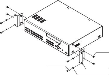
8. RACK MOUNTING
Use the optional MB-23B Rack Mounting Bracket when mounting the Digital Video Recorder in an equipment rack. Remove 4 rubber feet on the bottom surface by loosening their respective fixing screws with a standard screwdriver.
C-DR091 Series
C-DR161 Series
M4 x 12 binding head screw (supplied with the MB-23B)
M5 x 12 binding head screw |
MB-23B (optional) |
(supplied with the MB-23B) |
M5 fiber washer
(supplied with the MB-23B)
Note
•Use the Digital Video Recorder in locations with ambient temperature of between +5°C and +40°C (41°F and 104°F). When rack-mounting the Digital Video Recorder, the ambient temperature must be kept 35°C (95°F) or below.
•Be sure to mount the Digital Video Recorder below the heat generating components, and mount the perforated panel between the Recorder and such a heat generating component as required.
•The Digital Video Recorder has a built-in cooling fan. Never block the Recorder’s ventilation slot.
•Avoid installing the Digital Video Recorder in locations exposed to vibration.
a)Elevated Operating Ambient Temperature - If installed in a closed or multi-unit rack assembly, the operating ambient temperature of the rack environment may be greater than room ambient. Therefore, consideration should be given to installing the equipment in an environment compatible with the manufacturer's maximum rated ambient temperature (Tmra).
b)Reduced Air Flow - Installation of the equipment in a rack should be such that the amount of air flow required for safe operation of the equipment is not compromised.
c)Mechanical Loading - Mounting of the equipment in the rack should be such that a hazardous condition is not achieved due to uneven mechanical loading.
d)Circuit Overloading - Consideration should be given to the connection of the equipment to the supply circuit and the effect that overloading of circuits might have on overcurrent protection and supply wiring. Appropriate consideration of equipment nameplate ratings should be used when addressing this concern.
e)Reliable Earthing - Reliable earthing of rack-mounted equipment should be maintained. Particular attention should be given to supply connections other than direct connections to the branch circuit (e.g., use of power strips).
19
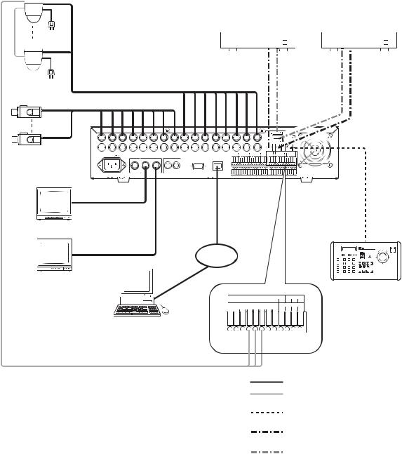
9. CONNECTIONS
9.1. Basic System
Combination camera


 *2
*2
To AC Mains


 *2
*2
RS-485
Color camera
1 2 3 4 5 6 7 8 9
*1 |
|
VIDEO |
AC MAINS |
|
|
Digital Video Recorder |
|
|
C-DR161 Series |
1 2 |
IN OUT |
|
LINK MONITOR OUT |
AUDIO |
MONITOR MONITOR
OUT1 OUT2
Monitor 1
Live only
Monitor 2
HDD Expansion Unit |
HDD Expansion Unit |
C-DA1000-2 |
C-DA1000-2 |
|
|
|
|
|
|
|
|
|
|
|
|
|
|
|
|
|
|
DISK |
|||
|
|
|
|
|
|
|
|
|
|
|
|
|
|
|
|
|
|
||||
|
|
|
|
|
|
|
|
|
|
|
|
|
|
|
|
|
ARRAY |
||||
|
|
|
|
|
|
|
|
|
|
|
|
|
|
|
|
|
|
|
|
RM |
|
|
|
|
|
|
|
|
|
|
|
|
|
|
|
|
|
|
|
|
|
|
|
|
|
|
|
|
|
|
|
|
IN |
|
|
|
|
|
|
|
|
|
|
TERMINATION |
|
|
|
|
|
|
|
|
|
|
|
|
|
|
|
|
|
|
|
|
|
|
ON |
|
|
|
|
|
|
|
|
|
|
|
|
|
|
|
|
|
|
|
|
|
OFF |
10 |
11 |
12 |
13 |
14 |
|
15 |
|
16 |
1 |
|
DISK ARRAY |
|
|
2 |
RM IN-A |
RM IN-A |
|||||
|
|
|
|
|
|
|
|
|
OUT |
|
|
|
|
|
|
|
|
|
|
|
|
|
|
|
|
|
ALARM IN |
|
|
|
|
PRIORITY |
NC |
|
CAMERA |
RM IN-B |
RM OUT-B |
||||||
|
|
|
1 G 2 |
G 3 |
G 4 |
G 5 |
G 6 |
G 7 |
G 8 |
G |
IN |
|
G |
+ |
G - |
+ |
G - |
+ |
G - |
||
|
|
|
|
|
|
|
|
|
|
|
|
|
|
|
CONTROL OUT |
|
|
TIME SYNC |
|||
|
|
|
9 G 10 |
G 11 |
G 12 |
G 13 |
G 14 |
G 15 |
G 16 |
G |
1 |
|
G |
2 |
G |
3 G |
4 |
G IN |
G |
OUT G |
|
RS-232C 100BASE-TX
10BASE-T/ 100BASE-TX
DVR CONTROL
OUTPUT-A
LAN
|
|
|
|
|
Remote Controller |
PRIORITY |
NC |
CAMERA |
RM IN-B |
RM OUT-B |
C-RM1000 |
|
|||||
IN G |
|
+ G - + G - + G - |
|
||
|
|
CONTROL OUT |
|
TIME SYNC |
|
1 G |
2 |
G 3 G |
4 G IN |
G OUT G |
|
PC
CAMERA
+ G -
RS-485
*1 C-DR091 and C-DR161 Series
C-DR091: 9 I/ O Terminals
C-DR161: 16 I/ O Terminals
*2 Match the Combination Camera’ s address to the Digital Video Recorder’ s video input number.
:Coaxial cable (Video signal)
:CPEV-S 0.65-3C (RS-485 Control line) Twisted pair with shield 22AWG or larger
:Modular cable, 3 m (9.8 ft). (supplied with the C-RM1000)
:Modular cable, 1 m (3.3 ft) (supplied with HDD expansion unit)
:S-ATA cable, 1 m (3.3 ft) (supplied with HDD expansion unit)
9.2. About Star Wiring
A C-IF500 Interface Unit is required when using star wiring for a Combination Camera’s control lines (RS485). Refer to the Interface Unit’s instruction manual for specific details on control line connections.
20

9.3. Digital Video Recorder’s Expansion System (Cascade connection)
Notes
•A cascade-connected system generally requires the Remote Controller(s).
•It is necessary to set DVR-ID in the cascade-connected system. (Refer to p. 27; Setting the DVR -ID.)
Interface unit 

 C-RF1000
|
REMOTE CONTROLLER |
|
||
1 |
2 |
3 |
4 |
POWER/DVR |
INTERFACE UNIT C-RF1000
DVR CONTROL |
REMOTE |
|
CONTROLLER |
||
OUTPUT-A |
||
INPUT-B |
||
|
Group 1
Combination camera
RS-485
To AC Mains
RM IN-A |
Termination: OFF |
|
|
|
|
|
|
|
|
|
|
|
|
|
|
|
|
|
|
|
|
|
|
|
|
|
|
|
|
|
|
|
|
|
|
|
|
|
|
|
|
|
|
RM |
|
|
|
|
|
|
|
|
|
|
|
|
|
|
|
|
|
|
|
|
|
|
|
|
|
|
|
|
|
|
|
IN |
|
|
|
|
|
|
|
|
|
|
|
TERMINATION |
||
|
|
|
|
|
|
|
|
|
|
|
|
|
|
|
|
|
|
|
|
|
|
|
|
|
|
|
|
|
|
|
|
|
|
|
|
|
|
|
|
|
|
|
ON |
|
|
|
|
|
|
|
|
|
|
|
|
|
|
|
|
|
|
|
|
|
|
|
|
|
|
|
|
|
|
|
|
|
|
|
|
|
|
|
|
|
|
|
OFF |
|
|
1 |
2 |
3 |
4 |
5 |
6 |
7 |
8 |
9 |
10 |
11 |
12 |
13 |
|
14 |
|
|
|
|
15 |
|
|
|
|
16 |
1 |
DISK ARRAY |
|
2 |
|
RM IN-A |
|
|
|||||||||
|
LINK |
|
|
|
|
|
|
|
|
|
|
|
|
|
|
|
|
|
|
|
|
|
|
|
|
|
|
|
OUT |
|
|
|
|
|
|
|
|
|
|
|
|
|
|
|
|
|
|
|
|
|
|
|
VIDEO |
|
|
|
|
|
|
|
|
|
|
|
ALARM IN |
|
|
|
|
|
|
|
PRIORITY |
NC |
CAMERA |
|
RM IN-B |
|
RM OUT-B |
|
|||||||
|
|
|
|
|
|
|
|
|
|
|
|
|
1 |
G |
2 |
G |
3 |
|
G |
4 |
G |
5 |
G |
6 |
G |
7 |
|
G |
8 |
G |
IN |
G |
+ G |
- |
+ |
|
G |
- |
+ |
G |
- |
||
|
|
|
AC MAINS |
|
|
|
|
|
|
|
|
|
|
|
|
|
|
|
|
|
|
|
|
|
|
|
|
|
|
|
|
|
|
|
CONTROL OUT |
|
|
|
|
TIME SYNC |
|
||
*1 |
|
|
|
|
|
|
|
|
|
|
|
|
|
|
|
|
|
|
|
|
|
|
|
|
|
|
|
|
|
|
|
|
|
|
|
|
|
|
|
|
|
||
Digital Video Recorder 1 |
|
|
|
1 |
2 |
IN |
OUT |
|
|
|
|
|
|
|
|
|
|
|
|
|
|
|
|
|
|
|
|
|
|
|
|
|
|
|
|
|
|
|
|
|
|
||
C-DR161 Series |
|
|
LINK |
MONITOR OUT |
|
AUDIO |
|
RS-232C |
|
100BASE-TX |
|
|
|
|
|
|
|
|
|
|
|
|
|
|
|
|
|
|
|
|
|
|
|
|
|
|
|
|
|
|
|||
|
|
|
MONITOR |
|
|
|
|
|
|
|
10BASE-T/ |
|
|
|
|
|
|
|
|
|
|
|
|
|
|
|
|
|
|
||||||||||||||
|
|
|
|
|
|
|
|
|
|
100BASE-TX |
|
|
|
|
|
|
|
|
|
|
|
|
|
|
|
||||||||||||||||||
Group 1 |
|
OUT 1 |
|
|
|
|
|
|
|
|
|
|
|
|
|
|
|
|
|
|
|
|
|
|
|||||||||||||||||||
|
|
|
|
|
|
|
|
|
|
|
|
|
|
|
|
|
|
|
|
|
|
|
|
|
|
|
|
|
|
|
|
|
|
|
|
|
|
|
|||||
Master |
|
|
|
|
|
|
|
|
|
|
|
|
|
|
|
|
|
|
|
|
|
|
|
|
|
|
|
|
|
|
|
|
|
|
|
|
|
|
|
|
|
||
Monitor |
|
|
|
|
|
|
To LAN |
|
|
|
|
|
|
|
|
|
|
|
|
|
|
|
|
|
|
|
|
|
|
|
|
|
|
|
|
|
|
|
|
|
|||
|
|
|
|
MONITOR |
|
|
|
|
|
|
|
|
|
|
|
|
|
|
|
|
|
|
|
|
|
|
|
|
|
|
|
|
|
|
|
|
|
|
|
||||
|
|
|
|
|
|
|
|
|
|
|
|
|
|
|
|
|
|
|
|
|
|
|
|
|
|
|
|
|
|
|
|
|
|
|
|
|
|
|
|
|
|||
Monitor 1 |
|
|
OUT 2 |
|
|
|
|
|
|
|
|
|
|
|
|
|
|
|
|
|
|
|
|
|
|
|
|
|
|
|
|
|
|
|
|
|
|
|
|
|
|||
|
|
|
|
|
|
|
|
|
|
|
|
|
|
|
|
|
|
|
|
|
|
|
|
|
|
|
|
|
|
|
|
|
|
|
|
|
|
|
|
|
|||
|
|
|
|
|
|
|
|
|
|
|
|
|
PRIORITY |
NC |
|
|
CAMERA |
|
|
|
|
RM IN-B |
|
|
|
RM OUT-B |
|
- |
|
|
|||||||||||||
|
|
|
|
|
|
|
|
|
|
|
|
|
IN G |
|
|
+ G - + G - + G |
|
|
|
|
|||||||||||||||||||||||
|
|
|
|
|
|
|
|
|
|
|
|
|
|
|
CONTROL OUT |
|
|
|
|
|
|
|
|
TIME SYNC |
|
|
|
|
|
|
|||||||||||||
|
|
|
|
|
|
|
|
|
|
|
|
|
1 G |
2 |
|
G |
|
|
3 |
|
|
G |
|
4 |
|
|
G |
IN |
|
|
G |
OUT |
|
|
G |
|
|
||||||
Live only |
|
|
|
|
|
|
|
|
|
|
|
|
|
|
|
|
|
|
|
|
|
|
|
|
|
|
|
|
|
|
|
|
|
|
|
|
|
|
|
|
|
||
Monitor 2 |
|
|
|
|
|
|
|
|
|
CAMERA |
|
|
|
|
|
|
|
|
|
|
|
|
|
|
|
|
|
|
|
|
|
|
|
|
|
|
RM |
||||||
|
|
|
|
|
|
|
|
|
|
|
|
|
+ G - |
|
|
|
|
|
|
|
|
|
|
|
|
|
|
|
|
|
|
|
|
|
|
|
|
|
|
|
OUT-B |
||
|
|
|
|
|
RS-485 |
|
|
|
|
|
|
|
|
|
|
|
|
|
|
|
|
|
|
|
|
|
|
|
|
|
|
|
|
|
|
|
|
|
|
|
|
||
To AC Mains |
|
|
|
|
|
|
|
|
|
|
|
|
|
|
|
|
|
|
|
|
|
|
|
|
|
|
|
|
|
|
|
|
|
|
|
|
|
|
|
|
|
||
|
|
|
|
|
|
|
|
|
|
|
|
|
|
|
|
|
|
|
|
|
|
|
|
|
|
|
|
|
|
|
|
|
|
|
|
|
|
|
|
|
Termination: OFF |
||
|
|
|
|
|
|
|
|
|
|
|
|
|
|
|
|
|
|
|
|
|
|
|
|
|
|
|
|
|
|
|
|
|
|
|
|
|
|
|
|
|
RM |
|
|
|
|
|
|
|
|
|
|
|
|
|
|
|
|
|
|
|
|
|
|
|
|
|
|
|
|
|
|
|
IN |
|
|
|
|
|
|
|
|
|
|
|
TERMINATION |
||
|
|
|
|
|
|
|
|
|
|
|
|
|
|
|
|
|
|
|
|
|
|
|
|
|
|
|
|
|
|
|
|
|
|
|
|
|
|
|
|
|
|
|
ON |
|
|
|
|
|
|
|
|
|
|
|
|
|
|
|
|
|
|
|
|
|
|
|
|
|
|
|
|
|
|
|
|
|
|
|
|
|
|
|
|
|
|
|
OFF |
1 |
2 |
3 |
4 |
5 |
6 |
7 |
8 |
9 |
10 |
11 |
12 |
13 |
|
|
14 |
|
|
|
|
15 |
|
|
|
16 |
|
1 |
|
DISK ARRAY |
|
|
2 |
|
RM IN-A |
|
|||||||||
|
|
|
|
|
|
|
|
|
|
|
|
|
|
|
|
|
|
|
|
|
|
|
|
|
|
|
|
|
OUT |
|
|
|
|
|
|
|
|
|
|
|
|
|
|
|
|
|
|
|
|
|
|
|
VIDEO |
|
|
|
|
|
|
|
|
|
|
|
ALARM IN |
|
|
|
|
|
|
|
PRIORITY |
|
CAMERA |
|
RM IN-B |
|
RM OUT-B |
||||||||
|
|
|
|
|
|
|
|
|
|
|
|
|
1 |
G |
2 |
G |
3 |
G |
4 |
G |
5 |
G |
6 |
G |
7 |
G |
8 |
G |
IN |
G |
NC + G |
- |
|
+ |
G |
|
- |
+ G |
- |
||||
*1 |
AC MAINS |
|
|
|
|
|
|
|
|
|
|
|
|
|
|
|
|
|
|
|
|
|
|
|
|
|
|
|
|
|
|
|
CONTROL OUT |
|
|
|
|
TIME SYNC |
|
||||
|
|
|
|
|
|
|
|
|
|
9 |
G |
10 |
G |
11 |
G |
12 |
G 13 |
G 14 |
G |
15 |
G |
16 |
G |
1 |
G |
2 |
G 3 |
G |
4 |
G |
|
IN |
G OUT G |
||||||||||
|
|
|
|
|
|
|
|
|
|
|
|
|
|
|
|
|
|
|
|
|
|
|
|
|
|
|
|
|
|
|
|
|
|
|
|
|
|
|
|
|
|||
Digital Video Recorder 2 |
|
|
|
1 |
2 |
IN |
OUT |
|
|
|
|
|
|
|
|
|
|
|
|
|
|
|
|
|
|
|
|
|
|
|
|
|
|
|
|
|
|
|
|
|
|
||
C-DR161 Series |
|
|
LINK |
MONITOR OUT |
|
AUDIO |
|
RS-232C |
|
100BASE-TX |
|
|
|
|
|
|
|
|
|
|
|
|
|
|
|
|
|
|
|
|
|
|
|
|
|
|
|
|
|
|
|||
|
|
|
|
|
|
|
|
|
|
|
|
|
|
|
|
|
|
|
|
|
|
|
|
|
|
|
|
|
|
|
|
|
|
|
|
|
|
|
|
|
|||
|
|
|
|
|
|
|
|
|
|
|
|
|
10BASE-T/ |
|
|
|
|
|
|
|
|
|
|
|
|
|
|
|
|
|
|
||||||||||||
|
|
MONITOR |
|
|
|
|
|
|
|
100BASE-TX |
|
|
|
|
|
|
|
|
|
|
|
|
|
|
|
||||||||||||||||||
|
|
|
|
|
|
|
|
|
|
|
|
|
|
|
|
|
|
|
|
|
|
|
|
|
|
|
|
|
|
|
|
|
|
|
|
|
|
|
|
||||
|
|
|
OUT 1 |
|
|
|
To LAN |
|
|
|
|
|
|
|
|
|
|
|
|
|
|
|
|
|
|
|
|
|
|
|
|
|
|
|
|
|
|
|
|
||||
Live only |
|
|
|
|
|
|
|
|
|
|
|
|
|
|
|
|
|
|
|
|
|
|
|
|
|
|
|
|
|
|
|
|
|
|
|
|
|
|
|||||
|
|
|
|
|
|
|
|
|
|
|
RM IN-B |
|
|
|
|
|
|
|
|
|
|
|
|
|
|
|
|
|
|||||||||||||||
|
|
|
|
MONITOR |
|
|
|
|
|
|
|
|
|
|
|
|
|
|
|
|
|
|
|
|
|
|
|
|
|||||||||||||||
|
|
|
|
|
|
|
|
|
|
PRIORITY |
|
|
|
|
|
CAMERA |
|
|
|
|
RM IN-B |
|
|
|
RM OUT-B |
|
|||||||||||||||||
|
|
|
|
OUT 2 |
|
|
|
|
|
|
|
NC |
|
|
|
|
|
|
|
|
|
|
|
||||||||||||||||||||
|
|
|
|
|
|
|
|
|
|
|
IN |
G |
|
|
+ |
|
G |
|
- |
|
+ |
|
G |
|
|
- |
+ |
|
|
G |
|
- |
|||||||||||
Monitor 2 |
|
|
|
|
|
|
|
|
|
|
|
|
|
|
CONTROL OUT |
|
|
|
|
|
|
|
|
|
TIME SYNC |
|
|
||||||||||||||||
|
|
|
|
|
|
|
|
|
|
1 |
G |
2 |
|
|
|
G |
|
3 |
|
|
G |
|
4 |
|
G |
|
IN |
G |
|
OUT |
G |
||||||||||||
|
|
|
|
|
|
|
|
|
|
|
|
|
CAMERA |
|
|
|
|
|
|
|
|
|
|
|
|
|
|
|
|
|
|
|
|
|
|
|
|
|
RM |
||||
|
|
|
|
|
|
|
|
|
|
|
|
|
+ G - |
|
|
|
|
|
|
|
|
|
|
|
|
|
|
|
|
|
|
|
|
|
|
|
|
|
|
|
|
OUT-B |
|
*2
Remote Controller 1
C-RM1000
 AC adaptor
RS-485
*2
Remote Controller 2
C-RM1000
RS-485
*1 C-DR091 and C-DR161 Series
C-DR091: 9 I/ O Terminals
C-DR161: 16 I/ O Terminals
*2 For the maximum cable length between the C-RF1000 Interface Unit and the C-RM1000 Remote Controller, refer to C-RM1000 operation manual.
RS-485
: Coaxial cable (Video signal)
:CPEV-S 0.65-3C (RS-485 Control line) Twisted pair with shield 22AWG or larger
 : Modular cable, 3 m (9.8 ft)
(supplied with the C-RF1000)
To next page
21
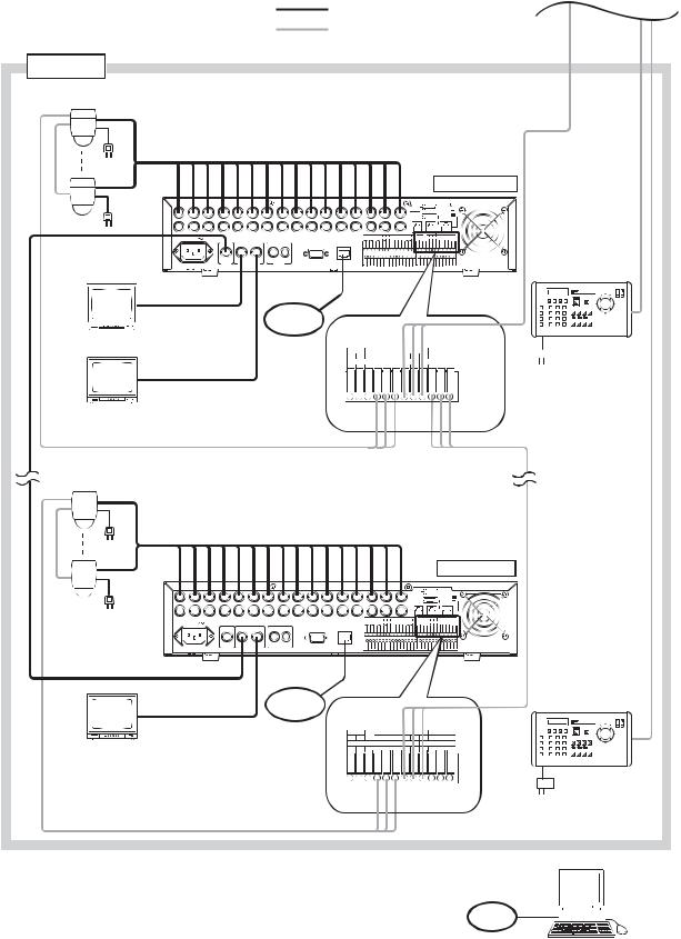
From previous page
: Coaxial cable (Video signal)
:CPEV-S 0.65-3C (RS-485 Control line) Twisted pair with shield 22AWG or larger
Group 2
*1
*2
Combination camera
RS-485
To AC Mains
Termination: OFF
1 |
2 |
3 |
4 |
5 |
6 |
7 |
8 |
9 |
10 |
11 |
||
|
LINK |
|
|
|
|
|
|
|
|
|
|
|
|
|
|
AC MAINS |
|
|
|
|
|
VIDEO |
|
|
|
*1 |
|
|
|
|
|
|
|
|
|
|||
|
|
|
|
|
|
|
|
|
|
|||
Digital Video Recorder 3 |
|
|
|
1 |
2 |
IN |
OUT |
|
|
|
||
C-DR161 Series |
|
|
LINK |
MONITOR OUT |
|
AUDIO |
|
RS-232C |
|
|||
|
|
|
MONITOR |
|
|
|
|
|
|
|
||
Group 2 |
OUT 1 |
|
|
|
|
|
|
|
|
|||
Master |
|
|
|
|
|
|
|
|
|
|
||
Monitor |
|
MONITOR |
|
|
To LAN |
|
|
|||||
|
|
|
|
|
|
|
|
|||||
OUT 2
Monitor 1
|
|
|
|
|
|
|
|
|
|
|
|
|
|
|
RM |
|
|
|
|
|
|
|
|
IN |
|
|
|
|
|
|
|
TERMINATION |
|
|
|
|
|
|
|
|
|
|
|
|
|
|
|
|
|
ON |
|
|
|
|
|
|
|
|
|
|
|
|
|
|
|
|
OFF |
12 |
13 |
14 |
|
15 |
|
16 |
1 |
|
DISK ARRAY |
|
2 |
RM IN-A |
|
|||
|
|
|
|
|
|
|
OUT |
|
|
|
|
|
|
|
|
|
|
|
|
ALARM IN |
|
|
|
|
PRIORITY |
NC |
|
CAMERA |
RM IN-B |
RM OUT-B |
|||
|
1 G 2 |
G 3 |
G 4 |
G 5 |
G 6 |
G 7 |
G 8 |
G |
IN G |
+ |
G - |
+ |
G - |
+ |
G - |
|
|
|
|
|
|
|
|
|
|
|
|
CONTROL OUT |
|
|
TIME SYNC |
||
|
9 G 10 |
G 11 |
G 12 |
G 13 |
G 14 |
G 15 |
G 16 |
G |
1 G |
2 |
G |
3 G |
4 |
G IN |
G |
OUT G |
100BASE-TX
10BASE-T/ 100BASE-TX
RM IN-B
Live only
Monitor 2
RS-485
Combination camera
PRIORITY |
NC |
+ |
CAMERA |
- |
RM IN-B |
RM OUT-B |
- |
|||
IN G |
|
G |
+ |
G |
- |
+ G |
||||
|
|
|
CONTROL OUT |
|
|
|
TIME SYNC |
|
||
1 |
G |
2 |
G |
3 |
G |
4 |
G |
IN |
G OUT |
G |
CAMERA |
RM |
+ G - |
OUT-B |
Termination: ON
|
|
|
|
|
|
|
|
|
|
|
|
|
|
|
|
|
|
|
|
|
|
|
|
|
|
|
|
RM |
|
|
|
|
|
|
|
|
|
|
|
|
|
|
|
|
|
|
|
|
|
IN |
|
|
|
|
|
|
|
|
|
TERMINATION |
|||
|
|
|
|
|
|
|
|
|
|
|
|
|
|
|
|
|
|
|
|
|
|
|
|
|
|
|
|
|
|
|
ON |
|
|
|
|
|
|
|
|
|
|
|
|
|
|
|
|
|
|
|
|
|
|
|
|
|
|
|
|
|
|
|
OFF |
|
1 2 3 4 |
5 |
6 |
7 |
8 9 |
10 11 |
12 |
13 |
|
|
14 |
|
15 |
|
|
|
16 |
|
1 |
|
DISK ARRAY |
|
2 RM IN-A |
|
|
||||||
|
|
|
|
|
|
|
|
|
|
|
|
|
|
|
|
|
|
OUT |
|
|
|
|
|
|
|
|
|
|
|
|
|
|
|
|
|
|
VIDEO |
|
|
|
|
|
|
ALARM IN |
|
|
|
|
|
|
PRIORITY |
NC |
|
CAMERA |
|
RM IN-B |
|
RM OUT-B |
|
||||
*1 |
|
|
|
|
|
|
1 |
G |
2 |
G 3 |
G 4 |
G |
5 |
G |
6 |
G 7 |
G |
8 |
G |
IN |
G |
+ |
G |
- + |
G |
- |
+ |
G |
- |
||
AC MAINS |
|
|
|
|
|
|
|
|
|
|
|
|
|
|
|
|
|
|
|
|
|
|
CONTROL OUT |
|
TIME SYNC |
|
|||||
|
|
|
|
|
|
9 |
G |
10 |
G 11 |
G 12 |
G |
13 |
G |
14 |
G 15 |
G |
16 |
G |
1 |
G |
2 |
G |
3 |
G 4 |
G |
IN |
G |
OUT |
G |
||
|
|
|
|
|
|
|
|
|
|
|
|
|
|
|
|
|
|
|
|
|
|
|
|
|
|
|
|
|
|
|
|
Digital Video Recorder 8 |
|
|
|
|
|
|
|
|
|
|
|
|
|
|
|
|
|
|
|
|
|
|
|
|
|
|
|
|
|
|
|
C-DR161 Series |
|
1 |
2 |
IN |
OUT |
|
|
|
|
|
|
|
|
|
|
|
|
|
|
|
|
|
|
|
|
|
|
|
|
|
|
|
LINK |
MONITOR OUT |
|
AUDIO |
RS-232C |
100BASE-TX |
|
|
|
|
|
|
|
|
|
|
|
|
|
|
|
|
|
|
|
|
|
|
|
|
|
|
|
|
|
|
|
|
10BASE-T/ |
|
|
|
|
|
|
|
|
|
|
|
|
|
|
|
|
||||||||
|
MONITOR |
|
|
|
|
|
100BASE-TX |
|
|
|
|
|
|
|
|
|
|
|
|
|
|
||||||||||
|
|
|
|
|
|
|
|
|
|
|
|
|
|
|
|
|
|
|
|
|
|
|
|
|
|
|
|
|
|
|
|
|
OUT 1 |
|
|
|
To LAN |
|
|
|
|
|
|
|
|
|
|
|
|
|
|
|
|
|
|
|
|
|
|
|
|
|
|
|
|
|
|
|
|
|
|
|
|
|
|
|
|
|
|
|
|
|
|
|
|
|
|
|
|
|
|
|
|
|
|
Live only |
MONITOR |
|
|
|
|
|
RM IN-B |
|
|
|
|
|
|
|
|
|
|
|
|
|
|
|
|||||||||
|
|
|
|
|
PRIORITY |
|
|
|
CAMERA |
|
|
|
RM IN-B |
|
|
|
RM OUT-B |
|
|
|
|||||||||||
|
OUT 2 |
|
|
|
|
|
NC |
|
|
|
|
|
|
|
|
|
|
|
|||||||||||||
|
|
|
|
|
|
IN |
G |
|
+ |
|
G |
|
- |
+ |
|
G |
|
- |
|
+ |
|
G |
|
|
- |
|
|||||
Monitor 2 |
|
|
|
|
|
|
|
|
|
|
CONTROL OUT |
|
|
|
|
|
|
|
|
TIME SYNC |
|
|
|
|
|||||||
|
|
|
|
|
|
1 |
G |
2 |
|
G |
|
3 |
|
G |
4 |
|
|
G |
|
IN |
|
|
G |
|
OUT |
|
G |
|
|||
CAMERA
+ G -
RS-485
C-DR091 and C-DR161 Series
C-DR091: 9 I/ O Terminals
C-DR161: 16 I/ O Terminals
For the maximum cable length between the C-RF1000 Interface Unit and |
LAN |
|
the C-RM1000 Remote Controller, refer to C-RM1000 operation manual. |
||
|
*2
Remote Controller 3
C-RM1000
 AC adaptor
RS-485
*2
Remote Controller 4
C-RM1000
PC
22
10. EXTERNAL TERMINAL CONNECTIONS
10.1. RS-232C Terminal Communications Specifications
The Digital Video Recorder can be controlled by a PC or other equipment via a connection through the RS232C port. However:
Notes
•Control software is not available as standard accessory.
•TOA takes no responsibility for hardware or software failures or damages resulting from the use of thirdparty control software.
10.1.1. Communications protocol
Transfer System: Start/stop system
Parity Bit: Even number
Transfer Speed: 9,600 bps, 19,200 bps, and 38,400 bps
Code: Binary code
Bit Length: 8 bits
Flow Control: CTS/RTS handshake or none
Stop Bit: 1
Error Control: None
10.1.2. RS-232C Connector pin arrangement
The following signal names are assigned to each pin of the RS-232C D-sub 9P male connector:
Terminal No. |
Symbol |
Name |
1 |
NC |
Not connected |
2 |
RD |
Receiving data |
3 |
SD |
Sending data |
4 |
NC |
Not connected |
5 |
SG |
Signal ground |
6 |
NC |
Not connected |
7 |
RS |
Request to send |
8 |
CS |
Clear to send |
9 |
NC |
Not connected |
Note
RS-232C connector plug is supplied with the Digital Video Recorder. For RS-232C connection to PC, use null modem cable.
15
69
23
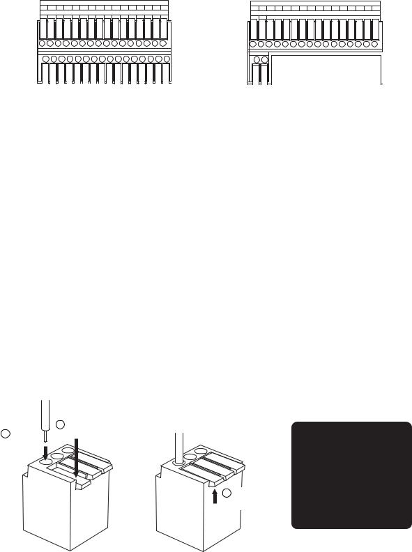
10.2. Alarm Input Terminal Connections
The number of terminals available differs depending on whether the Digital Video Recorder is a 9-channel or a 16-channel version. Refer to the table below when making alarm input terminal connections.(Refer to p. 14; Nomenclature and Functions)
|
|
|
|
For 16 channel |
|
|
|
|
|
For 9 channel |
||||||
|
|
|
|
|
ALARM IN |
|
|
|
|
|
|
|
|
ALARM IN |
||
1 |
G |
2 |
G |
3 G |
4 |
G |
5 |
G |
6 |
G 7 |
G |
8 |
G |
1 |
G |
2 G 3 G 4 G 5 G 6 G 7 G 8 G |
9 |
G |
10 |
G |
11 G |
12 |
G |
13 |
G |
14 |
G 15 |
G |
16 |
G |
9 |
G |
|
Terminal name |
Symbol |
Name |
1 |
ALARM 1 |
Alarm input 1 |
G |
GND |
Signal ground |
2 |
ALARM 2 |
Alarm input 2 |
G |
GND |
Signal ground |
3 |
ALARM 3 |
Alarm input 3 |
G |
GND |
Signal ground |
4 |
ALARM 4 |
Alarm input 4 |
G |
GND |
Signal ground |
5 |
ALARM 5 |
Alarm input 5 |
G |
GNA |
Signal ground |
6 |
ALARM 6 |
Alarm input 6 |
G |
GND |
Signal ground |
7 |
ALARM 7 |
Alarm input 7 |
G |
GND |
Signal ground |
8 |
ALARM 8 |
Alarm input 8 |
G |
GND |
Signal ground |
Terminal name |
Symbol |
Name |
9 |
ALARM 9 |
Alarm input 9 |
G |
GND |
Signal ground |
10 |
ALARM 10 |
Alarm input 10 |
G |
GND |
Signal ground |
11 |
ALARM 11 |
Alarm input 11 |
G |
GND |
Signal ground |
12 |
ALARM 12 |
Alarm input 12 |
G |
GND |
Signal ground |
13 |
ALARM 13 |
Alarm input 13 |
G |
GNA |
Signal ground |
14 |
ALARM 14 |
Alarm input 14 |
G |
GND |
Signal ground |
15 |
ALARM 15 |
Alarm input 15 |
G |
GND |
Signal ground |
16 |
ALARM 16 |
Alarm input 16 |
G |
GND |
Signal ground |
10.2.1. Terminal connection
The terminal connector is unlocked by pressing down on its release button. To connect the cable, press down on the release button first, insert the cable, then push the release button up again to lock the cable in place. However, for solid cables with diameters from 0.8 mm(AWG20) to 1.2 mm(AWG16), there is no need to press down on the release button. Cable can be connected simply by inserting it in place until it will not go any further.
Note
Ensure that the cable is securely locked into the terminal after connection.
1 |
Press down the |
2 |
Release button. |
Insert a cable. |
|
3 Push the
release button up.
Applicable cable
•Solid conductor AWG26 (ø 0.4 mm) - AWG16 (ø 1.2 mm)
•Stranded conductor AWG24 (0.2 mm2) - AWG20 (0.75 mm2)
24
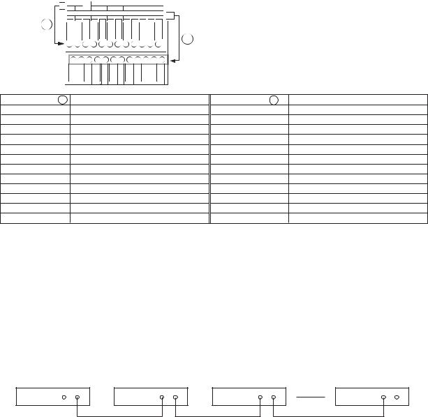
10.3. Control I/O Terminal Connections
The control input and output terminals include: priority recording terminal, camera control terminal, remote controller input/output terminals, control output terminal, and time synchronization input/output terminals. (Refer to p. 14; Nomenclature and Functions.)
PRIORITY |
NC |
+ |
CAMERA |
|
RM IN-B |
RM OUT-B |
- |
|||
IN G |
|
G - + |
G |
- |
+ G |
|||||
|
|
|
CONTROL OUT |
|
|
|
TIME SYNC |
|
||
1 |
G |
2 |
G |
3 |
G |
4 |
G |
IN |
G OUT |
G |
A


 B
B
Terminal name A PRIORITY IN PRIORITY G NC
CAMERA +
CAMERA G
CAMERA -
RM IN-B +
RM IN-B G
RM IN-B -
RM OUT-B + RM OUT-B G RM OUT-B -
Name
Priority Recording Input
Priority Recording Ground Not connected
Camera Control (RS-485) + Camera Control (RS-485) Ground Camera Control (RS-485) - Remote Control Input B + (RS-485) Remote Control Input B Ground Remote Control Input B - (RS-485)
Remote Control Output B + (RS-485) Remote Control Output B Ground Remote Control Output B - (RS-485)
Terminal name B |
Name |
CONTROL OUT 1 |
Control Output 1 |
CONTROL OUT G |
Control Output Ground |
CONTROL OUT 2 |
Control Output 2 |
CONTROL OUT G |
Control Output Ground |
CONTROL OUT 3 |
Control Output 3 |
CONTROL OUT G |
Control Output Ground |
CONTROL OUT 4 |
Control Output 4 |
CONTROL OUT G |
Control Output Ground |
TIME SYNC IN |
Date/Time Adjustment Input |
TIME SYNC G |
Date/Time Adjustment Input Ground |
TIME SYNC OUT |
Date/Time Adjustment Output |
TIME SYNC G |
Date/Time Adjustment Output Ground |
Note
Ensure that the cable is securely locked into the terminal after connection. (Refer to p. 24; Alarm input terminal connections.)
10.3.1. Time synchronization input/output terminal connections
Two different methods are available to synchronize the time, one using both master and slave units, the other using NTP. (Refer to p. 100; Date/time setting.)
Note
When synchronizing a single-channel Digital Video Recorder, set the synchronization interval to “5 seconds.” (Refer to p. 100; Date/time setting.)
Input Output |
Input Output |
Input Output |
Input Output |
Master |
Slave 1 |
Slave 2 |
Slave 7 |
To synchronize the times of slave units with the time of the master unit, connect the slave units to the master unit in a series via their input and output terminals. In other words, connect the input of slave number 1 to the master unit’s output and the input of slave number 2 to slave number 1’s output, and so on.
10.4. 10BASE-T/100BASE-TX Terminal Connections
Use this terminal to remotely monitor or control cameras connected to the Digital Video Recorder, or search or play back their recorded images on a PC web browser. When connecting a PC directly to the Digital Video Recorder, use a network crossover cable. Use the straight-through cable for connection between them via a switching hub.
25
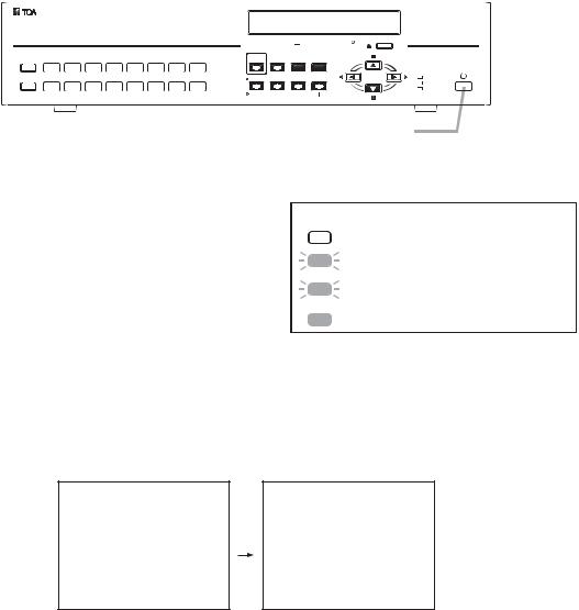
11. DIGITAL VIDEO RECORDER ACTIVATION AND TERMINATION
11.1. Recorder's Activation
|
|
|
|
|
|
|
|
|
|
|
DVD |
|
|
ARCHIVE |
1 |
2 |
3 |
4 |
5 |
6 |
7 |
8 |
PRIORITY |
BUZZER STOP/ |
|
MENU/ |
|
REC |
ALARM RESET |
SEARCH |
ENTER |
|
|||||||||
KEY LOCK |
9 |
10 |
11 |
12 |
13 |
14 |
15 |
16 |
|
|
MULTI |
|
REC |
MONITOR 1 |
ZOOM |
SCREEN |
SEQUENCE |
 FAILURE
 HD FULL
 MONITOR 2
DIGITAL VIDEO RECORDER C-DR161
Power key
1. Connect each component correctly. (Refer to p. 20; Connections.)
2.Insert the power supply plug.
The Recorder is placed in standby mode. The power key flashes at about 5-second intervals while in standby mode.
Note
Do not pull out the power supply plug while the Power key is light green. Ensure that the Recorder is in the standby mode when pulling out the power supply plug. Logged data could be damaged or lost if the power supply plug is pulled out during initialization (while accessing the hard disk).
Power key |
LED indicator |
Mode |
|
|
|
|
Distinguishes |
Main power OFF |
|
|
|
|
Flashes (5sec) |
Standby mode |
|
|
|
|
Flashes (1sec) |
During a system check |
|
(during activation) |
|
|
|
|
|
Lights |
Power ON (during operation) |
|
|
|
3.Press the Power key while the Recorder is in standby mode.
The screen automatically changes as shown below. The Power key flashes green during a system check. The Power key changes from flashing to steady ON after system check completion, allowing camera images to be displayed.
V e r  .
. 
S Y S T E M C H E C K I N P R O G R E S S .
P L E A S E W A I T .
Notes
•When the Recorder is used for the first time, the date and time could not be correctly displayed. Perform the clock setting before use. (Refer to p. 100; Date/time setting.)
•When the Digital Video Recorder is switched to standby mode, it cannot be switched on for about 10 seconds.
•Priority recording and auto-recording cannot be made in standby mode. Be sure to press the Power key when making recording.
11.2. Recorder's Power Off and Disconnect
Hold down the Power key for 2 seconds or more. All operations stop, placing the Recorder in standby mode. When moving the Recorder, be sure to place it in standby mode, then remove the power supply plug from the wall outlet.
26

12. INITIAL SETTINGS
Be sure to perform the following settings before using the Digital Video Recorder. Failure to do so may lead to incorrect operation of each function.
•DVR-ID setting (When cascade-connecting)
Note: When cascade-connecting the Digital Video Recorders, set the DVR-ID first. Otherwise, the Menu screen is not displayed.
•Clock settings
•Hard disk initialization
•Auto-Recording settings
12.1. Setting the DVR-ID
When cascade-connecting the Digital Video Recorders, set different DVR-ID for all individual Digital Video Recorders. DVR-ID are all factory-preset to "1." Follow the procedure below to set DVR number.
(Refer to p. 21; Digital Video Recorder's Expansion system.)
1.Press the Digital Video Recorder’s Power key while holding down the Sequence key in standby mode. Camera Selection keys 1 – 8 flashes for about 1minute.
2.Press the desired DVR-ID to set.
The selected number flashes three times, then the number is programmed as DVR-ID.
Note: It is impossible to operate the Digital Video Recorder when the main power is set to OFF. Operate the Digital Video Recorder after placing it in standby mode.
12.2. Clock Settings
Perform clock settings of the Digital Video Recorder. Adjust the date and time in Clock Settings on the menu screen. (Refer to p. 100; Date/time setting.)
Notes
•If the clock setting is not performed, video recordings are not made according to the schedule set in the auto-recording setting.
•In some cases, changing the current time may make it impossible to play back the recorded images correctly when duplicated time data exists in the recording data.
M A I N M E N U
R E C S E T T I N G
D I S P L A Y S E T T I N G N E T W O R K S E T T I N G M A I L S E T T I N G
S Y S T E M S E T T I N G L O G D I S P L A Y
D A T E / T I M E S E T T I N G M A I N T E N A N C E
I M A G E A R C H I V I N G
Menu key
D A T E / T I M E S E T T I N G |
|
|
|
D A T E / T I M E S E T T I N G |
|
|
|
J A N / |
1 / 0 5 |
0 0 : 0 0 : 0 0 |
|
D A T E / T I M E A D J U S T |
O P E R A T E |
S L A V E |
|
D A T E / T I M E A D J U S T T I M E |
0 0 : 0 0 |
||
D A T E / T I M E A D J U S T O U T P U T |
1 S E C |
||
D A Y L I G H T S E T T I N G |
|
|
O N |
S T A R T D A T E / T I M E |
|
|
|
A P R 1 S T |
W E E K S U N 0 2 : 0 0 |
||
E N D D A T E / T I M E
O C T L A S T W E E K S U N 2 2 : 0 0
1.Hold down the Menu key for 2 seconds or more. The main menu screen is displayed.
2. Move the cursor with the [  ] and [
  ] keys to select "DATE/TIME SETTING," then press the Menu key.
The clock setting screen is displayed.
3.Move the cursor with the [  ] and [
  ] keys and perform clock settings using the [+] and [-] keys. Set year, month, date, hour, minute, and second.
27

4.Press the [  ] key while the cursor is set to the leftmost selection item on the screen. The indication will appear to ask whether or not to save the setting.
5.Move the cursor with the [  ] and [
  ] keys, select "YES," then press the Menu key. The display reverts to the main menu screen.
12.3. Hard Disk Initialization
Set disk mode (normal mode and mirror mode) used for recording to the hard disk to initialize the hard disk. (Refer to p. 101; Equipment Maintenance.)
Notes
•Since initializing the hard disk erases all recorded images, be sure to copy the necessary data to DVD- R/RW disks or USB memory before initialization.
•Disk mode is factory-preset to "NORMAL." Leave the disk mode as it is when using the Digital Video Recorder in normal mode. However, it is recommended that the hard disk be initialized since recording starts automatically when the Digital Video Recorder's power is switched on.
M A I N T E N A N C E
H D I N I T I A L I Z E
S E T T I N G I N I T I A L I Z E L O G I N I T I A L I Z E
E X P O R T S E T T I N G D A T A I M P O R T S E T T I N G D A T A
U S B K E Y R E G I S T R A T I O N U S B K E Y D A T A E R A S U R E
D I S K A R R A Y 1
D I S K A R R A Y 2
E X E C U T E E X E C U T E E X E C U T E E X E C U T E E X E C U T E E X E C U T E
U N U S E D U N U S E D
Menu key
H D I N I T I A L I Z E |
|
|
|
D I S K M O D E N O R M A L |
|
||
E X E C U T E |
E X E C U T E |
|
|
H D D – A |
M A S T E R |
1 6 0 G B S L A V E |
- - - - - |
H D D – B |
M A S T E R |
1 6 0 G B S L A V E |
D V D |
1.Hold down the Menu key for 2 seconds or more. The main menu screen is displayed.
2.Move the cursor with the [  ] and [
  ] keys to select "MAINTENANCE," then press the Menu key. The Equipment Maintenance screen is displayed.
3.Select "HD INITIALIZE," then press the Menu key. The Hard Disk Initialization screen is displayed.
4.Select the disk mode using the [+] and [-] keys.
Select "NORMAL," or "MIRROR." (Refer to p. 38; Before Recording.)
5.Move the cursor with the [  ] and [
  ] keys to select "EXECUTE," then press the Menu key. "Yes" and "Cancel" are displayed.
6.Move the cursor with the [  ] and [
  ] keys to select "YES," then press the Menu key. Confirmation message is displayed after executing the hard disk initialization.
7.Select “OK,” then press the Menu key.
The display returns to the hard disk initialization screen.
28
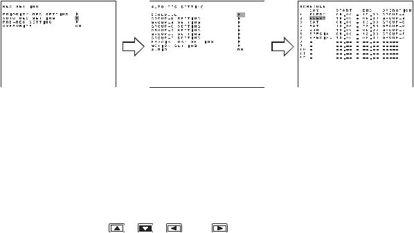
12.4. Auto-Recording Settings
Recordings are normally performed according to the preprogrammed schedule. Therefore, perform schedule or group settings when making auto-recording. (Refer to p. 79; Auto recording setting.)
12.4.1. Schedule setting
Set the schedule (Day, Start time, and End time) for each group to operate.
Menu key |
Menu key |
1.Hold down the Menu key for 2 seconds or more. The main menu screen is displayed.
2.Select "REC SETTING," then press the Menu key. The Recording setting screen is displayed.
3.Move the cursor with the [  ] and [
  ] keys to select "AUTO REC SETTING," then press the Menu key.
The Auto-recording setting screen is displayed.
4.Select "SCHEDULE," then press the Menu key.
5. Move the cursor with the [ |
], [ |
], [ |
], and [ |
] keys and perform schedule setting using the [+] |
and [-] keys. |
|
|
|
|
Set a day of the week, Start time, End time and manner of operation (group setting). (Refer to p. 79; Auto recording setting.)
6.Press the [  ] key while the cursor is set to the leftmost selection item on the screen. The indication will appear to ask whether or not to save the setting.
7.Move the cursor with the [  ] and [
  ] keys to select Yes, then press the Menu key. The display reverts to the auto-recording setting screen.
29

12.4.2. Setting the group
Perform individual settings such as Normal recording and Alarm Event recording for Group A - F.
A U T O R E C S E T T I N G
S C H E D U L E G R O U P – A S E T T I N G G R O U P – B S E T T I N G G R O U P – C S E T T I N G G R O U P – D S E T T I N G G R O U P – E S E T T I N G G R O U P – F S E T T I N G
S P E C I A L D A Y S E T T I N G M O T I O N S E T T I N G
A U D I O O N
Menu key
G R O U P – A S E T T I N G |
|
N O R M A L R E C S E T T I N G |
|
A L A R M E V E N T R E C S E T T I N G |
|
A L A R M E V E N T R E C M O D E |
S E Q U E N C E |
A L A R M I N P U T M O D E |
E D G E |
P O S T A L A R M T I M E |
9 9 9 S E C |
M O T I O N D E T E C T M O D E |
L E V E L |
P O S T M O T I O N T I M E |
1 S E C |
1.Choose “Group A-F” from the Auto-recording Settings and press the Menu key. The Group setting screen is displayed.
2. Move the cursor with the [  ], [
], [  ], [
], [  ], and [
  ] keys and perform Group setting using the [+] and [-] keys.
For a detailed information, refer to “Group A-F settings.“ (Refer to p. 80; Setting of groups A – F.)
3.Press the [  ] key while the cursor is set to the leftmost selection item on the screen. The indication will appear to ask whether or not to save the setting.
4.Move the cursor with the [  ] and [
  ] keys to select "YES," then press the Menu key. The display reverts to the auto-recording setting screen.
12.4.3. Other settings
In Auto-Recording Settings, “special day,” “motion detection,” and “audio (ON/OFF)” settings can be performed in addition to both schedule and group settings. (Refer to p. 79; Auto-recording setting.)
30
 Loading...