


10 & 12 SEER
AIR HANDLER
INSTALLATION & SERVICE MANUAL
MODELS: AH1-A, AH2-A
PLEASE READ THESE INSTRUCTIONS PRIOR TO INSTALLATION AND BEFORE PERFORMING ANY SERVICE OR MAINTENANCE. THESE INSTRUCTIONS MUST BE LEFT WITH THE USER AND SHOULD BE RETAINED FOR FUTURE REFERENCE BY QUALIFIED SERVICE PERSONNEL.


 : Improper installation, adjustment, alteration, service, or maintenance can cause injury or property damage. Refer to this manual. For assistance or additional information consult a qualified installer, service agency, or manufacturer listed below.
THERMO PRODUCTS, LLC. |
|
BOX 217 |
|
NORTH JUDSON, IN 46366 |
|
PHONE: (574) 896-2133 |
MADE IN USA |
MAC-165
ECN 4392-MA
TABLE OF CONTENTS |
|
SECTION |
BEGINNING PAGE |
SAFETY SECTION |
1 |
KNOCKDOWN OF AIR HANDLER |
3 |
REASSEMBLY OF AIR HANDLER |
3 |
INSTALLATION OF A-COIL IN A VERTICAL APPLICATION |
3 |
INSTALLATION OF A-COIL IN A HORIZONTAL APPLICATION |
4 |
INSTALLATION OF HOT WATER COIL |
6 |
BLOWER AIR ADJUSTMENT |
7 |
DUCT SYSTEM |
9 |
CFM CAPACITY CHARTS |
10 |
DUCT SIZING CHART |
11 |
INDOOR EVAPORATOR COIL |
11 |
TUBING LINE SETS |
12 |
SUPERHEAT MEASUREMENT |
15 |
MEASURING TEMPERATURE DROP |
16 |
ELECTRICAL |
17 |
UA ADAPTER CABINET |
17 |
RECOMMENDED SUSPENSION PROCEDURE FOR AH AIR HANDLER 18 |
|
REPLACEMENT PARTS LIST |
19 |
OUTLET AIR TEMPERATURE VS HEATING CAPACITY CHARTS |
20 |

All installations and services must be performed by qualified personnel.
SAFETY SECTION
This page contains various warnings and cautions found throughout this Service and Installation Manual. Please read and comply with the statements on the cover and the statements below.


 : Improper installation, adjustment, alteration, service, or maintenance can cause injury or property damage. Refer to this manual. For assistance or additional information consult a qualified installer, service agency, or manufacturer listed below.


 : If drilling or screwing into panel or plate is necessary, make certain drill or screw does not penetrate into any part of evaporator coil or hot water coil and cause damage. Personal injury and/or property damage may result.


 : Do not use this system if any part has been under water. Immediately call a qualified service agency to inspect the system and to replace any part of the electrical or control system which has been under water.


 : The cooling and heating coils must be cleaned by a qualified service person.


 : This air handler is not to be used to condition during construction.


 : When testing electrical equipment, always follow standard electrical procedures and precautions.


 : DO NOT wet electronic components during hydronic testing. Wetting electronic components may damage circuitry and cause a hazardous situation. Dry moisture from all leads and terminals if wetting occurs. Wait at least 24 hours for the circuit to fully dry before energizing the system.


 : Personal injury or property damage could result from major repair or service of this system by anyone other than a qualified contractor.


 : If you do not follow these instructions exactly an unsafe condition may result causing personal injury, loss of life or property damage.
1
All installations and services must be performed by qualified personnel.
Installation and service personnel are required by some states to be licensed. Persons not qualified shall not install this equipment nor interpret these instructions.
All local codes and regulations take precedence over the instructions in this manual and should be followed accordingly. In the absence of local codes, installation must conform with these instructions, regulations of the National Fire Protection Association and provisions of the National Electric Code.
AIR HANDLER
Each air handler is capable of operation within a range of evaporator coil sizes. The evaporator size specified is shipped as a separate item and must be installed by the contractor. Model AH2- A will accommodate the 1060-G1, 1242-G1, 1042E, and 1048E. The AH1-A will accommodate the 1024E, 1030E, 1036E, 1224-G1, 1230-G1 and 1236-G1.
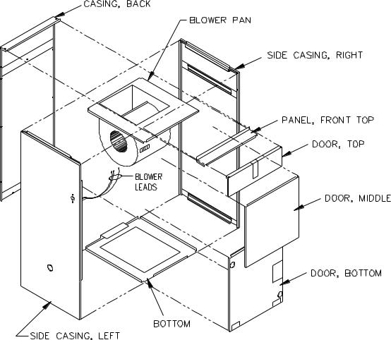
The construction of the air handler permits easy knockdown and reassembly. See Figure A.
Figure A
2
All installations and services must be performed by qualified personnel.
FOLLOW THESE STEPS FOR KNOCKDOWN OF AIR HANDLER:
1.Start with unit setting in a vertical position. (Figure A)
2.Remove screws from bottom door, middle door, top door, and top front panel. Remove doors and top panel of air handler.
3.Disconnect blower leads from blower terminal strip.
4.Remove screws that secure the blower pan to the side casings and the back casing.
5.Pull blower sub-assembly up and out the front of the unit.
6.Remove screws from the bottom and the casing back.
7.Remove casing back and side casings from the bottom.
REASSEMBLY OF AIR HANDLER
To reassemble the air handler, reverse steps above starting with number 7.
INSTALLATIONS OF A-COIL IN VERTICAL APPLICATIONS
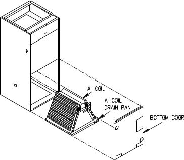
A standard Thermo Pride A-coil is used in all air handlers. The coil and its attached drain pan are installed in the air handler. See Figure B1.
Figure B1
3

All installations and services must be performed by qualified personnel.
INSTALLATIONS OF A-COIL IN HORIZONTAL APPLICATION
For the AH1-A, in all A-coil applications (1024E, 1030E, 1036E, and 1224-30G1) except the 1236G1, the A-coil spacer must be used.
For the AH2-A, in all A-coil applications the A-coil spacer must be used.
1.Remove bottom door of air handler.
2.Remove middle door of air handler.
3.Slide primary drain pan out of unit.
4.Set A-coil spacer in primary drain pan if needed. See Figure B2, #1 inset.
5.Set A-coil in place on primary drain pan.
6.Secure coil installation strip with aluminum tape as indicated in Figure B2, inset #2. This makes a small ramp to slide the coil up and on the rear pocket brake.
7.Slide pan with coil into air handler making sure that the A-coil plastic pan is properly positioned in the primary drain pan. Insure the plastic coil pan on base of the A-coil slides into rear clip. See Figure B2.
8.Secure front of plastic pan to bottom of unit with supplied pan clip. See Figure B3 inset. An extension for nut driver may be of benefit.
9.Pan should rest on pocket brakes on each side of side casing when properly installed. IMPORTANT: When air handler is installed in attic above a finished ceiling, it is recommended that a safety overflow pan with its own separate drain be installed under the entire unit.
10.Remove trim plate from A-coil connections.
11.Cut out appropriate holes in insulation, remove appropriate knockouts, and realign coil access panel and secure into place
12.Make appropriate liquid and suction line connections to coil and braze connections. NOTE: A wet rag makes an excellent heat sink for tubing.


 : If drilling or screwing into panel of plate is necessary, make certain drill does not penetrate into any part of evaporator coil or hot water coil to avoid personal injury and/or property damage.
4

All installations and services must be performed by qualified personnel.
13.Position grommets in coil access panel to allow installation of trim plate, secure trim plate in place with screws, and seal connections with duct sealer or equivalent.
NOTE: The air handler is factory assembled for left to right(horizontal) and vertical applications. If a right to left horizontal application is desired, the fan center must be moved to the right side casing which will position it above the primary drain pan.
Figure B2
5
 Loading...