


MT30
Page 1
Installation Instructions
for
Thermador
®
Microwave MBY
(Sold Separately)
Built-In Trim Kits • Models MT27 & MT30
IMPORTANT:
Local codes vary. Installation, electrical connections, circuit breakers
and grounding must comply with all applicable codes. Save these
instructions for the Local Electrical Inspector's use.
INSTALLER: Please leave these Installation Instructions with this unit for the
owner.
OWNER: Please retain these instructions for future reference.
WARNING: Disconnect power at the breaker before installing.
Please Read this entire manual before proceeding:
Ta b le of Contents
Step 1: Unpacking ............................................. 2
Step 2: Cabinet Preparation ........................... 3
Step 3: Electrical Installation ........................... 3
Step 4: Installing the Trim Kit .......................... 4
Step 5: Installing the Microwave Oven ......... 5
7
0
8
9
4
5 6
1
2
3
SENSOR
REHEAT
SENSOR
COOK
POWER
LEVEL
POP
CORN
TIMER
CLOCK
MORE
/LESS
QUICK
MIN
FUNCTION
KEY
SERVING
/WEIGHT
KEEP
WARM
TURBO
DEFROST
STOP/RESET START
Page 2
Step 1: Unpacking
A. Microwave Oven Model MBY (Sold Separately)
Open the box and carefully remove fillers and all packing material.
Included with your new Thermador microwave are the following:
• Care and Use manual (1)
• Quick Guide (1)
• Warranty Card (1)
• Turn Table (1)
• Turn Table Support (1)
B. Trim Kit Models MT27 & MT30
Open the box and carefully remove fillers and all packing materials.
Parts list:
• Trim Frame (1)
• Base Pan (1)
• Trim Bracket (2)
• Duct Side (1)
• Duct, Upper Exhaust (1)
• Duct, Top Intake (1)
• Duct, Rear Intake (1)
• Installation Instructions (1)
• 10-foot Roll Tape (1)
• Screws #8x1/4 (20)
• Grommet (1)
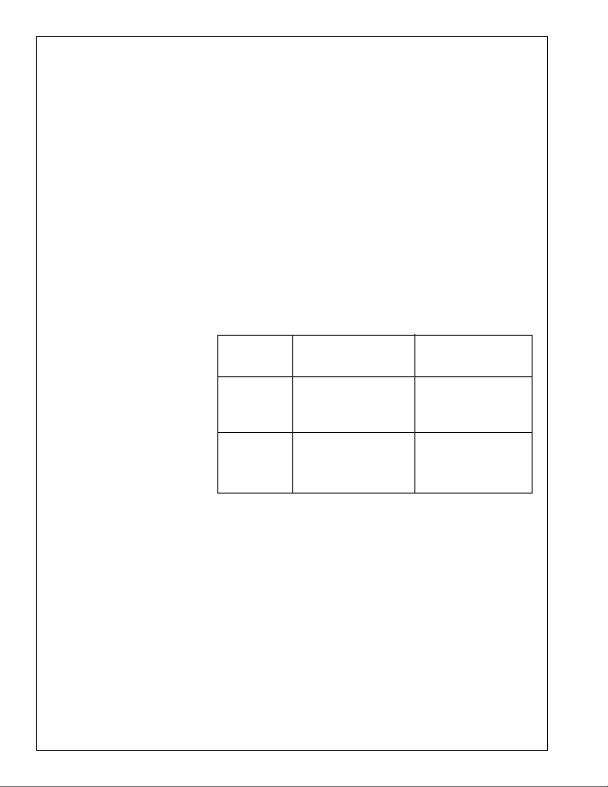
TRIM KITS Microwave Oven
Models
30" cabinet MT 30B (Black) MBYB
MT 30W (White) MBYW
MT 30S (Stainless) MBYS
27" cabinet MT27B (Black) MBYB
MT27W (White) MBYW
MT27S (Stainless) MBYS
Caution:
• This trim kit is designed for use only with the Thermador Microwave Oven Models Listed
(See Table 1)
• For Safety, do not alter or modify any part of this kit or oven
Ta b le 1
Page 3
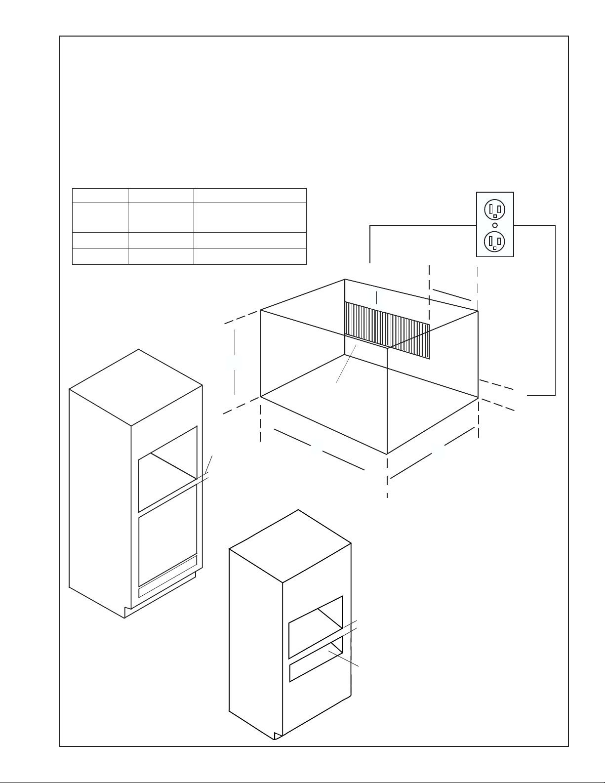
Step 2: Cabinet Preparation
4"
14"
4"
➛
➛
A
➝
➝
➝
➝
➛
➛
➛
➛
B
C
➛
➛
Figure 1.
Dimensions Trim Kits
Width (B) 28
-1
/
2
"±
1
/
16
MT30B; MT30W; MT30S
25
-1
/
2
"±
1
/
16
MT27B; MT27W; MT27S
Height (A) 17"±
1
/
16
All Trim Kits
Depth (C) 24"±
1
/
8
All Trim Kits
Outlet should be in
the shaded area.
Microwave
Cutout
Top of
microwave
shelf
1
-3
/4"
(45 mm)
}
Thermador
single wall
oven cutout
Figure 2.
• The cabinet cut out dimensions are shown in
Figure 1.
• It is good practice, when microwave oven is
installed at the end of a cabinet run, adjacent
to a perpendicular wall or cabinet door, to al-
low at least 1/4" space between the side of
the trim and the wall/door
•Your microwave oven can be installed into a
cabinet or wall by itself or above any of the
following
: Thermador wall ovens C271, C301,
CM301, S301, SC301, CJ301 or Thermador
Warming Drawers
WD 27 and WD 30 (See
Figure 2).
• Outlet should be in the shaded area as indi-
cated in Figure 1.
Step 3: Electrical
Installation
The Thermador micro-
wave oven is equipped with
a grounded cord. The wall
receptacle must be in-
stalled and grounded in ac-
cordance with the national
electrical code. Also, elec-
trical connections and
grounding must comply
with all applicable local
codes.
The electrical require-
ments for a separate circuit
serving only this micro-
wave oven are: 120v, 60Hz,
15amp.
➛
➛
Warming
Drawer
cutout
Microwave
cutout
1
-1
/2"
(38 mm)
➝
}
➛
➛
 Loading...