


Thermador TRUE, C301, C271, S302, CM301 User Manual
...
INSTALLATION INSTRUCTIONS
FOR THERMADOR® BUILT-IN ELECTRIC OVENS
Models:
C272 / C302 / CM302 / CJ302 / C271 / C301 / CM301
S272 / SC272 / SCD272 / S302 / SC302 / SCD302 / S301 / SC301 / SMW272 / SM272
Please read this entire instruction manual before proceeding.
IMPORTANT: Local codes vary. Installation, electrical connections, circuit breakers and grounding must comply with all applicable codes. Save these instructions for the Local Electrical Inspector's use.
INSTALLER: Please leave these Installation Instructions with this unit for the owner.
OWNER: Please retain these instructions for future reference.
WARNING: Disconnect power at the breaker before installing.
TABLE OF CONTENTS |
|
STEP 1: UNPACKING ............................................................................................ |
2 |
STEP 2: CABINET PREPARATION ..................................................................... |
2 |
STEP 3: ELECTRICAL INSTALLATION ............................................................. |
6 |
STEP 4: INSTALLING THE OVEN ...................................................................... |
7 |
STEP 5: INSTALLING THE BOTTOM TRIM .................................................... |
8 |
STEP 1: UNPACKING
Cut the bands from the carton. Carefully remove the carton, fillers and all packing material. Included with your new Thermador oven are the following:
Number of Racks Per Oven Model |
|
C272/C302/CM302 |
6 |
SCD272/SCD302 |
6 |
SC272/SC302 |
5 |
S272/S302/CJ302 |
4 |
SC301/C271/C301/CM301/SMW272/SM272 3 |
|
S301 |
2 |
One 2-Piece Broiler Pan
Care & Use Manual
Installation Instructions
Bottom Trim
Installation Screws (Packet)
Quick Guide
Cookbook (C, CJ and CM models only)
Fig. 1 Oven Base Attachment
|
Remove Screws - |
Shipping base skid |
4 places |
The bottom trim is shipped, wrapped in waxed paper, on top of the unit and should not be unpacked until the final step when the oven has been placed in the cabinet. See Fig. 6.
STEP 2: CABINET PREPARATION
The cabinet cutout dimensions for wall mounted and under the counter installations are shown in Figs. 2 and 3, respectively.
It is good practice, when oven is installed at the end of a cabinet run, adjacent to a perpendicular wall or cabinet door, to allow at least 1/4" space between the side of the oven door and the wall/door.
Wall Mounted Units —
For oven support, install 2 x 4’s extending front to back flush with the bottom and the side of the opening.
The supporting base must be well secured to the floor/ cabinet and level with the floor line.
NOTE: The conduit box for double ovens (S272, SC272, SCD272, S302, SC302, SCD302, C272, C302, CM302, CJ302, SMW272 and SM272) should be located above the unit to facilitate connecting and servicing. For single ovens (S301, SC301, C271, C301 and CM301) the conduit box may be installed either above or below the unit. If the conduit box is installed below the unit, a 2" diameter hole or space is required between the back wall and the right rear of the 2 x 4 supports. See Fig. 2
When an oven is installed, the cabinet base must be capable of supporting the oven weight as listed below:
Oven |
Pounds |
Kilograms |
S-series Single Oven |
165 |
75 |
C-series Single Oven |
210 |
95 |
CM Single Oven |
240 |
109 |
S-series Double Oven |
330 |
150 |
C-series Double Oven |
355 |
161 |
CM/CJ Double Oven |
370 |
168 |
Page 2
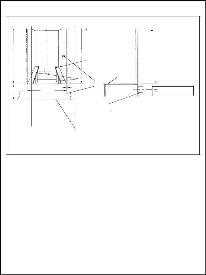
Fig. 2- Cabinet Cutout - Wall Mounted Installation
|
|
|
FRONT VIEW |
|
SIDE VIEW |
||
|
|
|
F |
|
G |
||
|
|
|
|
||||
Preferred |
|
|
|
|
|||
Location |
|
C |
|||||
of Conduit |
|
||||||
Box |
Frame |
||||||
Overlap |
|||||||
|
|
|
|
||||
|
|
|
|
(Top) 3/8" |
|||
|
|
|
(1, 0 cm) |
||||
|
|
|
|
Cabinet |
|||
|
|
|
|
|
|
|
|
|
|
|
|
|
|
|
|
A |
|
|
|
|
|
|
|
E |
|
Recommended |
||||||||
|
|
|
|
|
|
|
|
2" Diameter Hole (4.5 cm) |
||||||||||
|
|
2x4 |
Supports |
|
|
|
|
|
||||||||||
|
|
|
|
|
|
|
|
|
|
|
|
|
|
|
||||
|
|
|
|
|
|
|
|
|
|
|
|
|
|
|
|
|
|
|
|
|
(Wall |
|
|
|
|
|
|
|
|
|
|
|
|
|
|
|
|
|
|
|
Stud) |
|
|
|
|
|
|
|
|
|
|
Exposed Edge Must |
||||
|
|
|
|
|
|
|
|
|
Post Supports |
|||||||||
|
|
|
|
|
|
|
|
|
be a Finish-Cut |
|||||||||
|
|
|
|
|
|
|
|
|
Required Near |
|||||||||
|
|
|
|
|
|
|
|
|
|
|
|
|||||||
|
|
|
|
|
|
|
|
|
Back |
|
|
H |
|
|
|
|
|
|
|
|
|
|
|
|
|
|
|
|
|
|
|
|
|
||||
|
|
|
|
|
|
|
|
|
|
|
|
|
|
|
|
|
|
|
|
|
|
|
|
|
|
|
|
|
|
|
|
|
|
|
|||
|
|
|
|
|
|
|
|
|
|
|
|
|
|
|
|
|
|
|
|
|
|
|
|
|
|
|
|
|
|
|
|
|
|
|
|
|
|
D |
|
|
B |
Side Frame Overlap |
|
|
|
|||||||||||
|
|
|
|
5/8" Cabinet |
|
|
|
|
|
|
|
|
||||||
|
|
|
|
|
|
|
|
(1, 6 cm) |
|
|
|
|
|
|
|
|
||
|
|
FLOOR LINE |
|
|
|
|
|
Conduit Box May be Placed Here |
||||||||||
Double Oven
Location of
Conduit Box
2-1/2" (6, 4 cm) Above
Unit
CONDUIT BOX IS NOT FURNISHED WITH UNIT
Approx. 5" (13 cm)
Refer to dimensions for specific ovens on Page 4
Page 3
 Loading...