


WR-25 Instruction Manual
Weather Report ™
Digital Weather Station
WR-25
index
Thank you for purchasing a Weather Report. Your package should contain a WR-25 console, wind sensor, temperature/humidity sensor, rain collector and this manual.
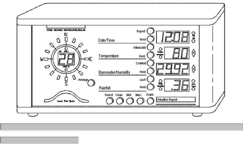
When in normal operation (no buttons depressed). the instrument displays current wind direction and speed, cycles current time and date, cycles current indoor, outdoor and if selected, aux temperatures (if both the indoor and outdoor indicator lights are extinguished, Aux. temperature is displayed) cycles current barometric pressure, current relative humidity, and cycles daily, monthly and term cumulative rainfall. By utilizing the hold buttons associated with each display, the user may select the most important readings to the user. When wind speed exceeds 99 miles per hour, a small green light will turn on between the digits of the wind speed display.
Trend indicators (arrows) are located to the right of the temperature, relative humidity, and barometric pressure displays. If, for example, the current relative humidity was increasing. the up trend arrow would be lit. If there was no change, no arrow would be lit.
index / top
We strongly suggest that all the weather station sensors be connected to the weather station and tested prior to installation so that you may become familiar with the operation of the instrument.
The WR-25 uses three sensors to gather weather data. The wind direction and speed sensor, the temperature and humidity sensor (a small black box) and the rain collector (see figure 1). The wind sensor and the rain collector are designed to mount to a television type mast (not provided). The cables from the sensors attach to the console via RJ-45 connectors in the rear of the unit. Each sensor has its own color coded plug, yellow for wind, blue for humidity/temperature and blue for rain. The blue connectors are interchangeable with each other.
Texas Weather Instruments, Inc. |
WR-25 Instruction Manual |

WR-25 Instruction Manual
The WR-25 wind direction and speed sensor is normally mounted on television type antenna masts (see Figure 1). For best results the wind sensor should be mounted at least 10 feet above the roof of the building. The higher the installation, the more accurate the readings. There is one yellow cable consisting of eight wires that must be strung from the wind sensor to the console. The wind direction sensor is calibrated at the factory and should be installed with the mounting arm pointed to the North. The wind sensor arm can be mounted and calibrated in any direction, but it is more convenient to use North as a reference. If calibration is necessary after the unit is already mounted, pick a calm day or immobilize the wind vane by hand. Enter calibration mode on the display (see
page 9) and step the direction around using the min or max key, or load the optional TWI_LOG program (see page 13) in your computer and change item 7, wind dir offset, until the proper direction achieved.
The outside temperature/humidity sensor should be mounted under the eaves, out of the rain and sun. The humidity sensor is light sensitive, if the humidity sensor cover is left off allowing light to hit the sensor element the humidity will read 0%. (If it is desirable to mount the temperature/humidity sensor directly on the mast, the optional pagoda housing should be secured at the time of purchase of the Weather Report.) One of the best places to mount this sensor is on the north side of the building where it is shaded most of the year. Remember, the sensor will detect the exact temperature and humidity where the sensor is located. If it is located above an air conditioning unit, it will read that artificially hot air -- location is very important! Ideally, the outside temperature/humidity sensor should be mounted with the sensor facing down. Mounting the sensor vertically is also satisfactory. Never mount the sensor face-up, exposed to rain. Water will collect in the sensor, creating inaccurate readings. Remove the four screws securing the cover of the temperature/humidity sensor, exposing two mounting holes. Mount the sensor utilizing the screws provided; replace the cover. This sensor has one blue cable which must be connected into the weather station. The optional outside temperature/humidity pagoda should be mounted about two feet under the wind sensor. Again we suggest at least a ten foot mast to overcome the artificially high readings generated by a hot roof.
The rain collector is normally mounted on the mast. It should be mounted as low as possible to reduce windage and to limit movement of the mast which can cause false readings. The collector should be mounted in a manner that allows rain to enter the collector unencumbered by surrounding obstacles. Use a bubble level to make sure that the collector is perfectly level with the ground. Failure to level the collector will cause inaccurate rainfall readings. The rain collector has one blue cable which must be connected to the console.
Plug the sensor cables and the serial cable into the connectors in the rear of the console. Plug the wall transformer into a 120V wall socket to power up the unit.
Texas Weather Instruments, Inc. |
WR-25 Instruction Manual |
WR-25 Instruction Manual
index / top
Select The select key, when pressed at the same time as the report key, puts the unit into time/date and lunar/tide cycle set mode. When the select and scale keys are pressed at the same time, the unit enters the calibration set mode. When the select and average keys are pressed at the same time, the unit enters the printer set mode. When select and last are pressed at the same time the instrument enters rainfall history set.
Clear The clear key, when depressed, causes the unit to display the date and time of the last memory clear. Pressing clear and minimum at the same time clears the unit's memory. Pressing clear and maximum at the same time also clears the unit's memory. Pressing clear and last rain clears the term rainfall.
Minimum The minimum key, when repeatedly depressed, steps through wind-speed/wind-direction, temperature, barometric pressure, humidity and rainfall rate, displaying the minimum reading of each of these functions since the last time the unit memory was cleared. In addition to the minimum reading, the unit displays the date and time of its occurrence. The date and time display must not be on hold in order to display both date and time.
Maximum The maximum key functions the same as the minimum key, but with maximum readings.
Scale The scale key changes the displays from reading in English values to those of Metric values. The inch light near the rain display is on when the instrument is in English mode. The
Texas Weather Instruments, Inc. |
WR-25 Instruction Manual |

WR-25 Instruction Manual
English to Metric equivalents are miles per hour or Knots to Kilometers per hour, Fahrenheit to
Celsius, Inches of Mercury to Millibars, Inches of rain to Centimeters of rain. Pressing the select and scale key at the same time puts the unit into calibration mode.
Report Pressing the report key sends current data to the serial port. The report key, when depressed at the same time as the select key, puts the unit into its time setting function.
Hold The hold key when depressed (toggled on) stops the cycling between two different parameters on the same display.
Windchill The windchill key, when depressed, calculates and displays, using wind speed and temperature, a factor which represents how cold the temperature and wind feel to bare flesh. Pressing the windchill and the comfort key at the same time will display the dew point.
Comfort The comfort key, when depressed, calculates and displays, using humidity and temperature, a factor which represents how warm the temperature feels.
Last The last key, when pressed, displays the time and date of the last rainfall and its rainfall rate. When pressed at the same time as the clear key, the instrument clears the term rainfall register. When last pressed at the same time as select, the unit enters into rainfall history mode.
Average When toggled on, the dot below the Av light (near the wind speed display), indicating that the unit is in wind averaging mode. When in wind averaging mode, the instrument displays the previous minute's average wind direction and speed. When pressing the average key and the select key at the same time, the unit enters into the printer set mode.
index / top
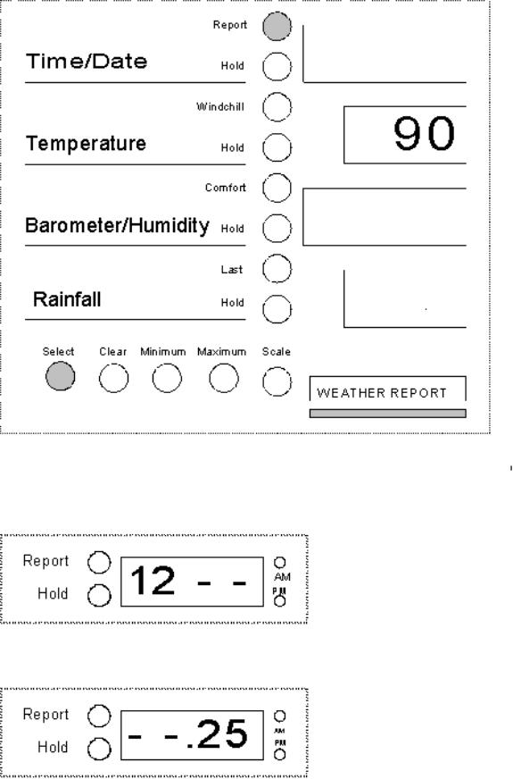
Press select and report at the same time, and the last two digits of the year displays (i.e., 90 = 1990). Press the maximum button to advance the year; the minimum button to retard the year.
Texas Weather Instruments, Inc. |
WR-25 Instruction Manual |
WR-25 Instruction Manual
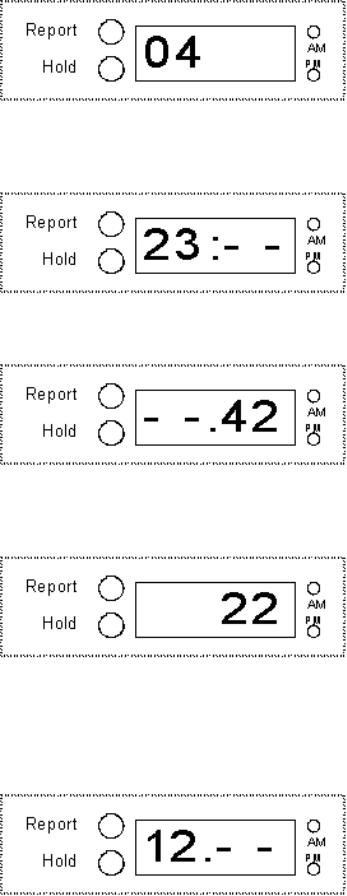
Press select a second time, and the month will be displayed (i.e., 1 = Jan. and 12 = Dec.). Press the maximum and minimum key to set the month.
Press select a third time, and the day of the month (1-31) digits light. Press the maximum to advance the date and minimum to retard the date.
Press select a fourth time, and the day of the week is displayed (1 = Sunday, 2 = Monday, 3 = Tuesday, 4 = Wednesday, 5 = Thursday, 6 = Friday, and 7 = Saturday. Press the maximum button to advance the day of the week and minimum to retard.
Texas Weather Instruments, Inc. |
WR-25 Instruction Manual |
WR-25 Instruction Manual
Press select a fifth time (note the colon between the hours and minutes), and the unit will display the time in military hour style. Press the maximum button to advance the hour or minimum to retard the hour.
Press select a sixth time (note the colon between the hours and minutes), and the unit will display minutes. Press the maximum or minimum buttons.
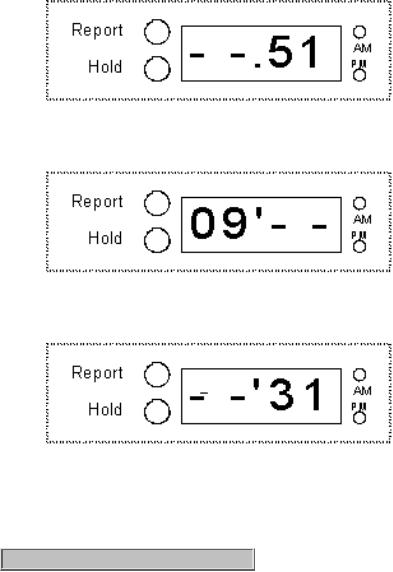
Press select a seventh time (note only the right two digits); the unit will display seconds. Press the maximum or minimum buttons to set the seconds. (note: the seconds is updated on the display only when the maximum or minimum button is being depressed).
Press select a eighth time (a single dot at the bottom separates the hour and minute); the lunar/tide clock will display the number of hours in a cycle.
Press the maximum or minimum buttons to set the hours of the cycle (explained in the Lunar Tide section).
Press select an ninth time (the single dot remains at the bottom, separating the hour and minute); the lunar/tide clock will display the minutes of the cycle. Press the maximum or minimum buttons to set the minutes of the cycle.
Texas Weather Instruments, Inc. |
WR-25 Instruction Manual |
WR-25 Instruction Manual
Press select a tenth time (the single dot is now located at the top, between the hour and minute); the peak of the cycle hour (usually high tide) will be displayed. Change as desired.
Press select an eleventh time (the single dot remains at the top between the hour and minute), and the minutes of the peak hour will be displayed. Change as desired.
Press select a twelfth time and the unit will return to normal display mode.
index / top
See the calibration reference section on page 18 for other details.
Calibration Method
Press select and scale at the same time, and the unit enters the calibration mode, first displaying the Aux temperature. (If the Aux dip switch is in the off position, the unit will skip this calibration). If necessary, press the maximum or minimum key to enter the proper temperature.
Texas Weather Instruments, Inc. |
WR-25 Instruction Manual |

WR-25 Instruction Manual
Press select a second time and the unit displays the indoor temperature. Press the maximum or minimum key to enter the actual temperature.
Press select a third time - the unit displays the outdoor temperature. Press the maximum or minimum key to enter the actual temperature.
Press select a fourth time, and the unit displays barometric pressure. Press the maximum or minimum key to enter the actual barometric pressure.
Texas Weather Instruments, Inc. |
WR-25 Instruction Manual |
 Loading...