


Telex
Operating Instructions
|
|
|
AUDIO |
|
I/C |
|
|
|
|
HEADSET |
|
IN |
OUT |
OUT TELEX IN |
|
|
|
|
|||
RadioComTM |
CHANNEL |
|
|
|
|
|||||
|
|
1 |
|
|
|
|
|
|
MIC |
|
|
|
|
1 |
RTS |
2 |
|
|
|
GAIN |
|
|
|
|
|
1 |
B |
2 |
||||
ON |
I/C |
|
AUTO |
|
A |
|
||||
B P |
IN |
OUT |
2 |
|
AUX |
|
|
|
|
|
EA |
|
|
|
|
|
VOL |
TALK/ |
|||
L C |
|
|
|
|
|
|
|
|
|
|
|
|
|
|
|
|
|
|
|
OM |
|
TK |
|
|
|
OFF |
|
ON |
|
|
|
|
|
|
|
|
CODE SWITCH |
|
|
||||
|
|
|
|
|
|
|
|
|
||
|
AUX |
|
|
|
|
|
|
|
|
|
OFF |
LOCAL |
BELT PACK |
|
|
|
|
|
|
|
|
|
|
|
|
|
|
|
|
|
|
|
BTR-600C |
SIDETONE |
|
|
|
|
|
|
|
|
|
|
|
|
|
|
|
|
|
|
TALK |
|
|
|
|
|
|
|
|
|
|
|
|
Telex
RadioCom™
BTR-500/600C
TR-500/600C
Professional
Wireless
Intercom Set
R
Table of Contents |
|
Introduction.......................................................................................................................................... |
1 |
General Description ......................................................................................................................... |
1 |
System Features ............................................................................................................................... |
1 |
Base Station Transceiver ..................................................................................................................... |
2 |
Controls And Connections............................................................................................................... |
2 |
Front Panel................................................................................................................................. |
2 |
Rear Panel .................................................................................................................................. |
3 |
Specifications................................................................................................................................... |
4 |
Beltpack Transceiver ........................................................................................................................... |
5 |
Controls and Connections................................................................................................................ |
5 |
Specifications................................................................................................................................... |
6 |
Initial Equipment Set-Up .................................................................................................................... |
7 |
Unpacking........................................................................................................................................ |
7 |
Antenna Information........................................................................................................................ |
7 |
Antenna Connections................................................................................................................. |
7 |
Antenna Polarization.................................................................................................................. |
8 |
Distance Between Antennas ...................................................................................................... |
8 |
Antenna Placement .................................................................................................................... |
8 |
Improving Reception/Increasing Range .................................................................................. |
10 |
Base Station Set-up ....................................................................................................................... |
11 |
Location ................................................................................................................................... |
11 |
Rack Mounting......................................................................................................................... |
11 |
Local Headset Connection ....................................................................................................... |
11 |
RF Transmit/Receive Channel Switches.................................................................................. |
11 |
RF Transmit Mode Switch....................................................................................................... |
12 |
Intercom Type Switch .............................................................................................................. |
12 |
Dual Listen Switches ............................................................................................................... |
12 |
Audio Channel Switch ............................................................................................................. |
13 |
Telex In/Out Switch ................................................................................................................. |
13 |
Auxiliary Switch ...................................................................................................................... |
13 |
Auxiliary to I/C Switch (program audio)................................................................................. |
13 |
Code Switch (BTR-600C Only)............................................................................................... |
13 |
Interconnection to a Hard-wired Intercom............................................................................... |
14 |
Auxiliary Audio Connection.................................................................................................... |
17 |
Power Connection.................................................................................................................... |
17 |
Dummy Load ........................................................................................................................... |
17 |
Beltpack Set-up.............................................................................................................................. |
18 |
Headset Connection ................................................................................................................. |
18 |
RF Transmit/Receive Channel Switches................................................................................. |
18 |
RF Transmit Mode Switch....................................................................................................... |
18 |
Code Switch (TR-600C Only) ................................................................................................. |
18 |
Battery Installation................................................................................................................... |
19 |
Pre-Walk-Thru Checklist.................................................................................................................. |
20 |
-i-
Table of Contents (Continued) |
|
System Operation............................................................................................................................... |
21 |
Base Station Operation .................................................................................................................. |
21 |
Power ....................................................................................................................................... |
21 |
Push-to-Talk/Lock-to-Talk Switch........................................................................................... |
21 |
Local Headset Volume ............................................................................................................. |
21 |
Microphone Gain ..................................................................................................................... |
21 |
Dual Listen Level..................................................................................................................... |
22 |
Intercom Level......................................................................................................................... |
22 |
Auxiliary Level ........................................................................................................................ |
22 |
Sidetone Level ......................................................................................................................... |
22 |
Beltpack Operation ........................................................................................................................ |
23 |
Power/Local Headset Volume.................................................................................................. |
23 |
Battery Check........................................................................................................................... |
23 |
Push-to-Talk/Lock-to-Talk Switch........................................................................................... |
23 |
Microphone Gain ..................................................................................................................... |
23 |
Sidetone Level ......................................................................................................................... |
24 |
Example System Configurations.................................................................................................... |
25 |
Single Base Station AudioCom (Telex) System ...................................................................... |
25 |
Single Base Station RTS System ............................................................................................. |
26 |
Six Base Station RTS System .................................................................................................. |
27 |
Eight Base Station Telex System ............................................................................................. |
28 |
Single Beltpack to Single Beltpack System............................................................................. |
29 |
System Walk-Thru............................................................................................................................. |
30 |
Troubleshooting.................................................................................................................................. |
31 |
Tech Tips............................................................................................................................................. |
32 |
Codes Settings and the BTR-600C ................................................................................................ |
32 |
Frequency Interaction .................................................................................................................... |
32 |
Microphone Gain Adjustment........................................................................................................ |
33 |
Battery Information........................................................................................................................... |
33 |
Intercom System Specifications ........................................................................................................ |
33 |
Accessories.......................................................................................................................................... |
34 |
Customer Service Information ......................................................................................................... |
35 |
FCC Information ............................................................................................................................... |
36 |
-ii-
Introduction
General Description
The Telex Radiocom BTR-500 and BTR-600C UHF Wireless intercom systems offer the ultimate in reliable, high performance, high fidelity full duplex communications.
The BTR-500 series includes the BTR-500 frequency agile base station, working with the TR-500 transceiver beltpack. The BTR-500 base station provides full duplex communications with a single beltpack. Sixteen BTR-500s, or more, may be operated simultaneously. Also a single BTR-500 base station can accommodate an unlimited number of beltpacks operating in “Push-to-Transmit” mode.
The BTR-600C series has all the features of the BTR-500 with the addition of digital modulation and encryption for secure communications. Base station and beltpacks can choose from over 65,000 user selectable security codes out of over 16 million possible codes by means of four cipher code switches on the units. Sixteen BTR-600C, or more, may be operated simultaneously, permitting 16, or more, discrete full duplex radio channels.
The BTR systems incorporate auto-switching 2 channel operation, permitting the beltpack operator to choose between 2 separate audio channels of communications, with the base station tracking the beltpack selection. Auto-switching allows the user the flexibility to create a party-line and a private line within the same beltpack.
The BTR-500 and BTR-600C systems are perfectly suited for stand-alone operation and also can interface with Audiocom® (Telex), RTS® TW, as well as RTS Matrix systems and other 4 wire communications systems. Clear-Com® intercom system may also be interfaced to a BTR-500 and BTR-600C systems through the use of a Telex to Clear-Com Interface box, see “Accesories” for more information. In addition to the external intercom systems interfaces listed above, the base stations provide connections for auxiliary balanced audio input and output.
The Radiocom BTR series has been designed for reliable, efficient operation. Operating in the 520 to 760 MHz range, the units operate reliable at distances of 1,000 feet. With available antenna systems from Telex, the effective operating range can be extended. The high efficiency beltpacks provide 12 hours of uninterrupted operation using standard alkaline batteries.
System Features
Compatible with Audiocom (Telex), RTS TW, RTS Matrix, Clear-Com (with external interface box), and other wired intercom types.
Intercom loop thru jacks for connecting multiple units.
Full Duplex (simultaneous talk and listen) operation.
Beltpack TR unit contained in a weather and shock resistant die cast magnesium case.
Digitally encrypted RF (Radio Frequency) link for secure communication on the 600C version.
Flexible power requirements. The base unit can be powered by any 12 to 15 Volt, AC or DC, 400 mA power source. An external AC wall supply is supplied with the unit.
Two transmit and two receive RF channels to help avoid radio interference.
Base stations are table or rack mountable.
Audio channel switch on the beltpack unit enables it to remotely control the intercom channel on the base unit.
Two channels of audio.
Beltpack batteries last up to 12 hours when using standard AA alkaline batteries.
Audio out jack for P.A. systems or other external audio systems.
RTS® and Audiocom® are registered trademarks of Telex Communications, Inc. Clear-Com® is a registered trademark of Clear-Com Intercom Systems, Inc.
-1-
Base Station Transceiver
Controls and Connections
1 |
|
|
2 |
3 |
4 |
9 |
10 11 |
14 |
15 16 17 |
18 |
|
|
|
|
|
|
|
AUDIO |
|
I/C |
|
HEADSET |
|
|
|
|
|
IN |
OUT |
OUT TELEX IN |
|
|
|
||
|
|
|
|
CHANNEL |
|
|
|
||||
|
RadioCom |
TM |
|
|
|
|
MIC |
|
|||
|
|
|
|
|
1 |
|
|
|
|
||
|
|
|
|
|
|
|
|
|
|
GAIN |
|
|
ON |
|
|
I/C |
|
AUTO |
A |
1 B |
2 |
|
|
|
BP |
|
IN |
OUT |
2 |
AUX |
|
VOL TALK/ |
|
||
|
EA |
|
|
|
|
|
|||||
|
L C |
|
|
|
|
OFF |
ON |
|
OM |
|
|
|
T K |
|
|
|
|
CODE SWITCH |
|
|
|||
|
|
|
|
|
|
|
|
|
|||
|
|
|
|
AUX |
|
|
|
|
|
|
|
|
OFF |
|
LOCAL |
|
BELT PACK |
|
|
|
|
|
|
|
|
|
|
|
|
|
|
|
|
|
|
|
BTR-600C |
|
|
|
|
|
|
|
|
|
|
|
|
|
|
SIDETONE |
|
|
|
|
|
TALK |
|
|
|
|
|
|
|
|
|
|
|
|
|
|
|
|
5 7 |
|
8 6 |
|
12 13 |
19 |
|
||
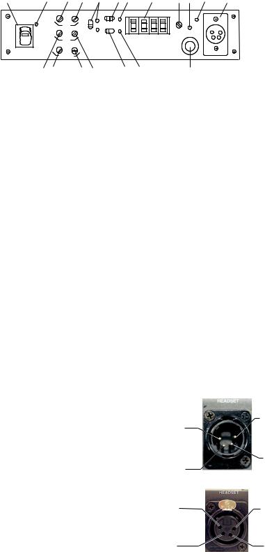
Figure 1
Front Panel Controls and Connections
1.Power Switch - Illuminates when on.
2.Beltpack Light - Illuminates when a beltpack is transmitting to base station.
3.Intercom In Level Control - Adjust for optimum level. Intercom light #11 should just flash red on loudest speech.
4.Intercom Out Level Control - Adjusts output to match input level of wired intercoms.
5.Auxiliary In Level Control - Adjust for optimum level. Auxiliary light #13 should just flicker from green to red on loudest sounds.
6.Auxiliary Out Level Control - Adjusts output to match input level of auxiliary equipment.
7.Sidetone Local Control - Adjusts level of voice feedback to earphone when a headset is plugged into jack #18.
8.Sidetone Remote Control - Controls sidetone level in the beltpack.
9.Audio Channel Switch And Lights -
A.“I/C” switch on rear panel set to Telex - Selects either “I/C 1 or 2" jack (and corresponding pins on ”I/C Loop Thru"). In “Auto” position; allows selection of channels 1 or 2 from the beltpack.
B.“I/C” switch on rear panel set to RTS - Selects RTS channel 1 or 2 on both I/C jacks (and corresponding pins on “IC Loop Thru”). In “Auto" position; allows selection of channels 1 or 2 from the beltpack.
10.Intercom Switch - See settings below.
A.“I/C” switch on rear panel set to “Telex”
1.“Telex Out” Setting - Intercom is disconnected from all “I/C” jacks on rear panel.
2.“Telex In” Setting - Intercom is connected to “I/C Loop Thru” and “I/C 1 or 2" jacks. Channel 1 or 2 is selected by switch #9 or the channel switch on the beltpack.
B.“I/C” switch on rear panel set to “RTS” - Switch has no effect. All I/C jacks on rear panel are active on either setting.
11.Intercom Light - Flashes red when input level is too high. See #3 for adjustment.
12.Auxiliary Switch - Turns the auxiliary input on and off.
13.Auxiliary Light - Illuminates green when switch #12 is on. Flashes red when input level is too high. See #5 for adjustment.
14.Code Switch (BTR-600C Only) - Allows user to select cipher code (over 65,000 available). Any combination of letters and/or numbers may be selected except 0000. Data is unencrypted when the setting is 0000. The code switch settings on the BTR-600C and TR-600C must match exactly.
15.Volume, Headset - Controls volume on headset plugged into #18
16.Talk/Overmodulation Light - Illuminates green when talk switch #19 is on. Flashes red when headset microphone is over modulated - See #17 for adjustment.
17.Microphone Gain Control - Adjust so that light #16 just flickers from green to red on the loudest speech.
18.Headset Connector - Standard “XLR” type. Plug for Telex units and jack for RTS units. Wired as follows:
Telex Units
(1) Microphone |
(4) Headphone |
|
Low (-) |
||
Shield (-) |
||
|
||
(2) Microphone |
(3) Headphone |
|
High (+) |
||
Audio (+) |
||
|
||
|
|
RTS Units
(4) Headphone
Low (-) (1) Microphone
Shield (-)
(3) Headphone
High (+) (2) Microphone
Audio (+)
Figure 2 Headset Wiring
19.Talk Switch - Press-to-talk, release to disable. Press and release quickly to stay on.
-2-
Base Station
Controls and Connections - Rear Panel
|
1 |
3 |
|
|
|
|
|
|
|
|
|
|
15 |
|
TRANSMIT |
|
|
|
|
LOOP |
|
BTR-600C |
|
|
RECEIVE |
||
|
|
|
|
|
|
|
THRU |
|
|
|
|
|
|
ANT. |
|
AUDIO |
|
PUSH |
|
|
|
PUSH |
FCC ID. B5DM503 |
|
ANT. |
||
|
|
|
|
|
|
|
MADE IN U.S.A. |
|
|||||
|
OUT |
|
|
6 |
1 |
6 |
1 |
|
|||||
|
|
|
|
|
PATENT PENDING |
|
|
||||||
|
|
|
|
|
|
|
|
|
|
|
|
||
|
|
XMIT |
DUAL |
|
|
|
|
|
|
|
|
|
|
|
I /C |
MODE |
LISTEN |
|
|
|
|
|
|
|
|
|
|
|
TELEX |
RTS REMOTE |
CH2 + 2 |
|
|
9 |
5 |
9 |
5 |
|
|
|
|
|
A |
O |
O |
|
|
|
|
|
|
|
|
|
A |
|
|
F |
|
|
|
|
|
|
|
|
|
|
|
|
B |
F |
N |
|
|
|
|
|
|
|
|
POWER |
B |
|
|
|
|
I/C 1 |
|
|
|
I/C 2 |
|
|
|||
|
TRANSMIT |
|
CH2 + 1 |
|
|
I/C |
|
|
AUX |
12-15V |
RECEIVE |
||
|
CONT. |
LEVEL |
|
|
|
AC/DC |
|||||||
|
CHANNEL |
|
|
|
|
|
|
|
|
CHANNEL |
|||
|
|
|
|
|
|
|
|
|
|
||||
2 |
4 |
5 |
6 |
7 |
8 |
9 |
10 |
|
11 |
12 |
13 |
14 |
|
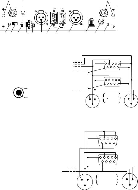
Figure 3
Controls and Connections - Rear Panel - BTR-600C
1.Transmit Antenna Jack - Color band on antenna must match color dot on base station. Female “TNC” Connector.
2.Transmit Channel Switch - Changes frequency of beltpack (shown on Serial No. Tag). Must match receive channel on beltpack.
Ground
3. Audio Out - “RCA” type jack
provides a high impedance out-
Audio Out
put for an audio amplifier.
4.I/C Switch - Set for Telex or RTS type intercom systems. See Figures 4 and 5.
5.Transmit Mode Switch -
A.“Remote” - The unit transmits only when the beltpack is transmitting.
B.“Off” - The unit does not transmit.
C.“Continuous” - The transmitter is on continuously. (Recommended Setting)
A. |
CH1+2=OFF |
Both audio channels are iso- |
|
CH2+1=OFF |
lated from each other. |
|
|
|
B. |
CH1+2=ON |
Audio channel 2 is mixed into |
|
CH2+1=OFF |
channel 1. |
|
|
|
C. |
CH1+2=OFF |
Audio channel 1 is mixed into |
|
CH2+1=ON |
channel 2. |
D. |
CH1+2=ON |
Both audio channels are |
|
CH2+1=ON |
mixed into each other. |
|
|
|
6.Dual Listen Switches
7.Dual Listen Level Control-Adjusts level of audio mix.
8.& 11. Intercom 1 and 2 Jacks -
A.I/C Switch (#4) set to Telex - “I/C 1" or ”I/C 2" (and matching pins on jacks 9 and 10) are selected by the Audio Channel switch on the front panel or the Channel switch on the base station.
If one or both intercom lines are not used, plug the Telex dummy load(s) into the appropriate unused jack(s).
1 |
5 |
69
15
69
|
PIN |
|
|
|
1 |
GROUND |
|
|
2 |
AUDIO |
|
2 1 |
3 |
+ AUDIO |
2 1 |
3 |
SWITCH #4 |
3 |
|
|
|
||
I/C 1 |
SET TO "TELEX" |
I/C 2 |
|
|
|
||
(CHANNEL 1) |
|
|
(CHANNEL 2) |
Figure 4
Intercom 1 and 2 Jacks - Switch set to Telex
1 |
5 |
69
15
69
|
PIN |
|
|
||
|
1 |
COMMON |
|
|
|
|
2 |
CHANNEL 1 |
2 |
1 |
|
2 1 |
3 |
CHANNEL 2 |
|||
|
|
||||
3 |
SWITCH #4 |
|
3 |
||
|
|
||||
IC/1 |
SET TO "RTS" |
IC/2 |
|||
|
|
||||
Figure 5
Intercom 1 and 2 Jacks - Switch set to RTS
B.I/C Switch (#4) set to RTS - “I/C 1" and ”I/C 2" are connected in parallel (including matching pins on jacks 9 and 10). Channels 1 and 2 are selected by the Audio Channel switch on the front panel or the channel switch on the base station.
If neither channel 1 or 2 are connected to other intercoms, plug the RTS dummy load into the “I/C 1 or 2" jack. Do not use the dummy load if the unit is connected to an RTS intercom system.
-3-

9.& 10. Loop Thru I/C - 9 pin D-sub jack. Wired as shown.
11.See #8.
12.Auxiliary Jack - 6 pin RJ-11 telephone type jack. Compatible with “RTS Matrix” type intercoms.
PIN 6 5 4 3 2 1
13.Power Jack - 12-15 VDC, 400mA minimum or 12-15 VAC rms, 400mA rms minimum. Accepts 5.5 mm x 2.1 mm plug.
14.Receive Channel Switch - Changes frequency of receiver (shown on Serial No. Tag). Must match transmit channel on beltpack.
13.Receive Antenna Jack - Color band on antenna must match color dot on base station. Female “TNC” Connector.
NC |
NC |
AUDIO IN - |
AUDIO IN + |
AUDIO OUT - |
AUDIO OUT + |
Figure 6
Auxiliary Jack
BTR-500/600C
Specifications
RF Output . . . . . . . . . . . . . . . . . . . . . . . . . . . . . . . . . . . . . . . . . . . . . 40 mW maximum, 25mW typical Temperature Range. . . . . . . . . . . . . . . . . . . . . . . . . . . . . . . . . . . . . . . . . -4°F to 130°F (-20°C to 55°C) Dimensions . . . . . . . . . . . . . . . . . . . . . . . . . . . . 8.25"W x 1.75"H x 11.25"D (21cm x 4.5cm x25.6cm) Weight . . . . . . . . . . . . . . . . . . . . . . . . . . . . . . . . . . . . . . . . . . . . . . . . . . . . . . . . . . . . . . . . 4 lbs. (1.8kg) Modulation Type
BTR-600C . . . . . . . . . . . . . . . . . . . . . . . . . . . . . . . . . . . . . . . . . . . . . . . . . . . . . . . . . . . . . . NFSK BTR-500 . . . . . . . . . . . . . . . . . . . . . . . . . . . . . . . . . . . . . . . . . . . . . . . . . . . . . . . . . . . . . . . . . FM
Deviation
BTR-600C . . . . . . . . . . . . . . . . . . . . . . . . . . . . . . . . . . . . . . . . . . . Complies with FCC 74.861e6 BTR-500 . . . . . . . . . . . . . . . . . . . . . . . . . . . . . . . . . . . . . . . . . . . . . . . . . . . . . . . . . . . . . ±40 KHz
Frequency Response
BTR-600C . . . . . . . . . . . . . . . . . . . . . . . . . . . . . . . . . . . . . . . . . . . . . . . . . . . . . . . . 300-4500 Hz BTR-500 . . . . . . . . . . . . . . . . . . . . . . . . . . . . . . . . . . . . . . . . . . . . . . . . . . . . . . . . . . 300-8000 Hz RF Frequency Stability . . . . . . . . . . . . . . . . . . . . . . . . . . . . . . . . . . . . . . . . . 0.005% crystal controlled
Modulation Limiter. . . . . . . . . . . . . . . . . . . . . . . . . . . . . . . . . . . . . . . . . . . . . . . . . Internal Compressor Microphone input sensitivity . . . . . . . . . . . . . . . . . . . . . . . . . . . . . . . . . . . . . . . . . . . . . . . . . 2.0-25 mV Radiated Harmonic and Spurious. . . . . . . . . . . . . . . . . . . . . . . . . Meets or exceeds FCC specifications Typically -45 dBc or better RF Frequency Range . . . . . . . . . . . . . . . . . . . . . . . . . . . . . . . . . . . . . . 520 to 608 and 614 to 760 MHz
Receiver sensitivity . . . . . . . . . . . . . . . . . . . . . . . . . . . . . . . . . . . . Less than 0.5 uV for 12 dB SINAD. I.F. Bandwidth
BTR-600C . . . . . . . . . . . . . . . . . . . . . . . . . . . . . . . . . . . . . . . . . . . . . . . . . . . . . 230 KHz at -3dB BTR-500. . . . . . . . . . . . . . . . . . . . . . . . . . . . . . . . . . . . . . . . . . . . . . . . . . . . . . . 150 KHz at -3dB Type . . . . . . . . . . . . . . . . . . . . . . . . . . . . . . . . . . . . . . . . . . Single Conversion Superhet, 10.7 MHz I.F. Image Rejection. . . . . . . . . . . . . . . . . . . . . . . . . . . . . . . . . . . . . . . . . . . . . . . . . . . . . . . . 70 dB or better Audio Output, Headset . . . . . . . . . . . . . . . . . . . . . . . . . . . . . . . . . . . . . . . . . . . . 32 mW into 600 Ohms
Squelch
BTR-600C . . . . . . . . . . . . . . . . . . . . . . . . . . . . . . . . . . . . . . . . . . . . . . . . . . . . . . Internal, 3.0 V BTR-500 . . . . . . . . . . . . . . . . . . . . . . . . . . . . . . . . . . . . . . . . . . . . . . . . . . . . . . . Internal, 1.5 V FCC . . . . . . . . . . . . . . . . . . . . . . . . . . . . . . . . . . . . . . . . . . . . . . . . . . . . . . . . . . . . . . . Transmit, Part 74 Receive, Verification, Part 15 FCC ID . . . . . . . . . . . . . . . . . . . . . . . . . . . . . . . . . . . . B5DM503 (BTR-600C), B5DM505 (BTR-500)
-4-
Beltpack
Controls and Connections
4
3 2 1 6
5
|
|
VOLUME |
TALK |
N O |
|
AUDIO |
|
|
|
|
F |
|
|
F |
|
|
O |
|
.M.O |
|
|
BAT/ |
|
1 |
|
|
CHANNEL |
|
|
2 |
|
|
|
x |
|
le |
||
e |
|
|
T |
|
|
M |
IC |
|
|
|
N |
|
I |
|
G |
A |
|
|
|
|
12 13
7 |
11 |
8
9
10
Figure 7
Controls and Connections
1.Volume Control and Power Switch - Turns power on and off and controls headset volume.
2.Battery/Overmodulation Light - Flashes once when unit is turned on if battery is good. If light stays on, battery is low. If light does not flash, battery is dead.
Flickering red light when talking means microphone gain is too high and speech will sound distorted. Adjust Mic Gain control #7 so that the light barely flashes on the loudest speech.
3.Talk Switch - Press to talk, release to disable. Press and release quickly to stay on continuously.
4.Talk Light - Illuminates when Talk function is on.
5.Audio Channel Switch - The Audio Channel Switch enables the beltpack user to switch between wired intercom channels 1 and 2 on the base station.
6.Side Tone Control - (Only installed in special beltpack to beltpack direct communications units). Adjusts level of voice feedback to earphone for a headset that is plugged into the jack #10. The “Remote Sidetone” on the base station controls the beltpack sidetone in standard units.
7.Microphone Gain Control - Adjust so the light #2 barely flashes on the loudest speech.
8.Code Switch (TR-600C Only) - Allows the user to select a cipher code (over 65,000 available). Any combination of letters and/or numbers may be selected except 0000. Data is unencypted when the setting is 0000. The code switch settings on the TR-600C and BTR-600C must match exactly.
9.Battery Latch - Press down to release the battery pack. Pack slides off in opposite direction.
10. Headset Connector - Standard “XLR” type. Plug for Telex units and jack for RTS units. Wired as shown.
(1) Microphone
(4) Headphone
Shield (-)
Low (-)
(3) Headphone
(2) Microphone High (+)
Audio (+)
Telex Units
(1) MICROPHONE SHEILD (-)
(2) MICROPHONE AUDIO (+)
RTS Units
(4) HEADPHONE |
(3) HEADPHONE |
LOW (-) |
HIGH (+) |
Figure 8
Headset Jack Wiring
11.Push-to-Talk/Push-to-Transmit - When the switch is set to “Push-to-Talk”, the transmitter in the beltpack is always on, but no audio signal is sent unless the Talk Switch #3 is activated. The “Push-to-Talk” switch setting is the recommended position.
When the switch is set to “Push-to-Transmit", the transmitter is turned on when the Talk Switch is activated and turned off when the talk switch is deactivated.
12.Receive Channel - Changes the frequency of the receiver. It must match the Transmit Channel of the base station.
13.Transmit Channel - Changes frequency of the transmitter. It must match Receive Channel of the base station.
-5-

Beltpack
Specifications
RF Output . . . . . . . . . . . . . . . . . . . . . . . . . . . . . . . . . . . . . . . . . . . . . . . . . . . . . . . . . . . . . 25mW typical Temperature Range. . . . . . . . . . . . . . . . . . . . . . . . . . . . . . . . . . . . . . . . . -4°F to 130°F (-20°C to 55°C) Dimensions. . . . . . . . . . . . . . . . . . . . . . . . . . . . 4"W x 5 7/8"H x 1 5/8"D (120mm x 149mm x 41mm) Weight . . . . . . . . . . . . . . . . . . . . . . . . . . . . . . . . . . . . . . . . . . . . . . . . . . 1 lb. 6 oz. (625g) with batteries Modulation Type
TR-600C . . . . . . . . . . . . . . . . . . . . . . . . . . . . . . . . . . . . . . . . . . . . . . . . . . . . . . . . . . . . . . . NFSK TR-500 . . . . . . . . . . . . . . . . . . . . . . . . . . . . . . . . . . . . . . . . . . . . . . . . . . . . . . . . . . . . . . . . . . . FM
Deviation
TR-600C . . . . . . . . . . . . . . . . . . . . . . . . . . . . . . . . . . . . . . . . . . . . Complies with FCC 74.861e6 TR-500 . . . . . . . . . . . . . . . . . . . . . . . . . . . . . . . . . . . . . . . . . . . . . . . . . . . . . . . . . . . . . . ±40 KHz
Frequency Response
TR-600C . . . . . . . . . . . . . . . . . . . . . . . . . . . . . . . . . . . . . . . . . . . . . . . . . . . . . . . . . . 300-4500 Hz TR-500 . . . . . . . . . . . . . . . . . . . . . . . . . . . . . . . . . . . . . . . . . . . . . . . . . . . . . . . . . . . 300-8000 Hz RF Frequency Stability . . . . . . . . . . . . . . . . . . . . . . . . . . . . . . . . . . . . . . . . . 0.005% crystal controlled
Modulation Limiter. . . . . . . . . . . . . . . . . . . . . . . . . . . . . . . . . . . . . . . . . . . . . . . . . Internal Compressor Microphone input sensitivity . . . . . . . . . . . . . . . . . . . . . . . . . . . . . . . . . . . . . . . . . . . . . . . . . 2.0-25 mV Radiated Harmonic and Spurious. . . . . . . . . . . . . . . . . . . . . . . . . Meets or exceeds FCC specifications Typically -45 dBC or better RF Frequency Range . . . . . . . . . . . . . . . . . . . . . . . . . . . . . . . . . 520 to 608 MHz and 614 to 760 MHz
Receiver sensitivity . . . . . . . . . . . . . . . . . . . . . . . . . . . . . . . . . . . . Less than 0.5 uV for 12 dB SINAD. I.F. Bandwidth
TR-600C. . . . . . . . . . . . . . . . . . . . . . . . . . . . . . . . . . . . . . . . . . . . . . . . . . . . . . . 230 KHz at -3dB TR-500 . . . . . . . . . . . . . . . . . . . . . . . . . . . . . . . . . . . . . . . . . . . . . . . . . . . . . . . . 150 KHz at -3dB Type . . . . . . . . . . . . . . . . . . . . . . . . . . . . . . . . . . . . . . . . . . Single Conversion Superhet, 10.7 MHz I.F. Image Rejection. . . . . . . . . . . . . . . . . . . . . . . . . . . . . . . . . . . . . . . . . . . . . . . . . . . . . . . . 70 dB or better Audio Output, Headset . . . . . . . . . . . . . . . . . . . . . . . . . . . . . . . . . . . . . . . . . . . . 32 mW into 600 Ohms
Squelch
TR-600 . . . . . . . . . . . . . . . . . . . . . . . . . . . . . . . . . . . . . . . . . . . . . . . . . . . . . . . . . Internal, 3.0 µV TR-500 . . . . . . . . . . . . . . . . . . . . . . . . . . . . . . . . . . . . . . . . . . . . . . . . . . . . . . . . . Internal, 1.5 µV FCC . . . . . . . . . . . . . . . . . . . . . . . . . . . . . . . . . . . . . . . . . . . . . . . . . . . . . . . . . . . . . . . Transmit, Part 74 Receive, Verification, Part 15 FCC ID . . . . . . . . . . . . . . . . . . . . . . . . . . . . . . . . . . . . . . . B5DM506 (TR-500), B5DM504 (TR-600C)
-6-
Initial Equipment Set-Up
Unpacking
Unpack your RadioCom System. A system package should contain the following Items:
Contact the shipper or your dealer immediately if anything is damaged or missing. Fill out the registration card and return it to Telex to properly register your unit.
Quantity |
Descripton |
|
|
1 |
BTR-500 or BTR-600C Base Station |
|
|
1 |
TR-500 or TR-600C Beltpack |
|
|
1 |
Wall Power Supply |
|
|
2 |
Antennas (one Transmit and one Receive) |
|
|
1 |
Interconnect Cable (9 pin to 9 pin) |
|
|
2 |
Dummy Loads (3 pin XLR male) |
|
|
1 |
Operating Instructions |
|
|
1 |
Warranty and Registration Card |
|
|
2 |
Plastic Screwdrivers |
|
|
4 |
Rubber Feet |
|
|
|
|
Antenna Information
Antenna Connection
The base station is supplied with two (2) antennas. One 1/2-wave antenna for Transmit and one 1/2-wave for Receive. The antennas have TNC male connectors.
The frequency range of the antennas should match the receiver and transmitter of the base station. Match the color code on the antenna with the color code on the base station.
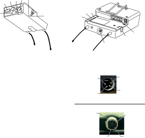
Attach the receive 1/2-wave antenna to the antenna input receptacle labeled “Receive” on the right side of the rear panel. The antenna should be vertically aligned.
Figure 9
Attaching Receive 1/2-Wave Antenna
-7-
Attach the transmit 1/2-wave antenna to the antenna input receptacle labeled “Transmit” on the left side of the rear panel. The antenna should be vertically aligned.
Figure 10
Attaching Transmit 1/2-Wave Antenna
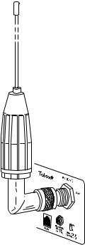
Antenna Polarization
The Telex Wireless Intercom System is “Vertically Polarized”. This means both the transmitting and receiving antennas should operate in the vertical position.
The antennas can be remoted for better signal path. A Telex coax assembly and/or a signal splitter/ combiner with remote antennas may be required. See “Accessory” section for ordering information.
NOTE: If your base station is to be located in a shielded rack mount enclosure or other poor RF location, you must remote the 1/2-wave antennas with coax assemblies or use a splitter/combiner (SC-600) with special broad band antennas. See “Example System Configurations” section for a multiple unit system using a SC600 and broad band antennas.
Antenna Placement
Proper antenna placement probably has the most effect on your TELEX Wireless Intercom System’s overall performance. The following suggestions will result in optimum performance.
Proper placement of the beltpack can be critical. The antennas should be in the open. Bending the antennas up and placing the beltpack in a pocket, etc., will reduce system distance.
It is suggested that the unit be worn on the belt or pocket with both antenna’s hung vertically for best operating range and performance.
Radio Com
A 1 
 B
B 
 2
2
BTR-600C
Telex
Telex
ANTENNAS MUST BE VERTICAL
Figure 11
Vertically Polarized Antenna
Distance between Antennas
The distance between the base station’s receive and transmit antennas is not adjustable when the antennas are connected directly on the back of the unit.
-8-
Figure 12
Proper Dressing of the Antennas
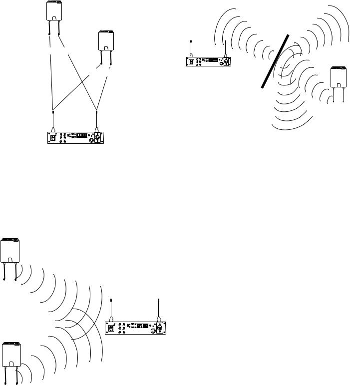
Keep the distance between the BTR and the TR as short as possible. The greater the distance, the weaker the signal. Make sure the “signal paths” between the BTR and TR are unobstructed. You should be able to visibly locate the antennas at all times for best performance.
Telex
Telex
700 FEET
100 FEET
|
|
|
|
AUDIO |
|
HEADSET |
|
|
IN |
OUT |
|
MIC |
|
Radio Com |
|
|
CHANNEL |
|
||
|
|
1 |
|
GAIN |
||
ON |
BP |
I/C |
|
AUTO |
A |
1 B 2 |
|
ELAC |
IN |
OUT |
2 |
|
VOL |
|
T K |
|
|
|
|
CODE SWITCH |
|
|
AUX |
|
|
|
|
OFF |
|
LOCAL |
BELT PACK |
|
|
|
BTR-600C |
|
|
|
|
|
|
|
|
SIDETONE |
|
|
|
TALK |
Figure 13
Distance Between base station and beltpack
Attempting to operate the wireless intercom system through or around walls, ceilings, metal objects, etc. will reduce system range and performance.
Radio Com
A 1 
 B
B 
 2
2
BTR-600C
Telex
Figure 15
Operating System Near Obstructions
Telex
|
|
|
|
AUDIO |
|
HEADSET |
|
|
IN |
OUT |
|
MIC |
|
Radio Com |
|
|
CHANNEL |
|
||
|
|
1 |
|
GAIN |
||
ON |
BP |
I/C |
|
AUTO |
A |
1 B 2 |
|
ELAC |
IN |
OUT |
2 |
|
VOL |
|
T K |
|
|
|
|
CODE SWITCH |
|
|
AUX |
|
|
|
|
OFF |
|
LOCAL |
BELT PACK |
|
|
|
BTR-600C |
|
|
|
|
|
|
|
|
SIDETONE |
|
|
|
TALK |
Telex
DO NOT - mount the base station 1/2-wave antennas on, or next to metal, such as beams, walls with metal studs, equipment racks, etc. This also applies to the antennas when assembled directly to the Base Station. This will “detune” the antennas which can result in noise or loss of RF signal at the Base Station, See Figure 15.
Figure 14
Keeping Site Clear to Antenna
-9-
 Loading...