


 Loading...
MS-2002
Master Station and Power Supply
User Manual
9350-7749-000 Rev J |
1/2010 |

PROPRIETARY NOTICE
The product information and design disclosed herein were originated by and are the property of Bosch Security Systems, Inc. Bosch reserves all patent, proprietary design, manufacturing, reproduction, use and sales rights thereto, and to any article disclosed therein, except to the extent rights are expressly granted to others.
COPYRIGHT NOTICE
Copyright 2010 by Bosch Security Systems, Inc. All rights reserved. Reproduction, in whole or in part, without prior written permission from Bosch is prohibited.
WARRANTY NOTICE
See the enclosed warranty card for further details.
CUSTOMER SUPPORT
Technical questions should be directed to:
Customer Service Department
Bosch Security Systems, Inc.
12000 Portland Avenue South
Burnsville, MN 55337 USA
Telephone: 800-392-3497
Fax: 800-323-0498
Factory Service: 800-553-5992 (Lincoln, NE)
RETURN SHIPPING INSTRUCTIONS
Customer Service Department
Bosch Security Systems, Inc. (Lincoln, NE) Telephone: 402-467-5321
Fax: 402-467-3279
Factory Service: 800-553-5992
Please include a note in the box which supplies the company name, address, phone number, a person to contact regarding the repair, the type and quantity of equipment, a description of the problem and the serial number(s).
SHIPPING TO THE MANUFACTURER
All shipments of product should be made via UPS Ground, prepaid (you may request from Factory Service a different shipment method). Any shipment upgrades will be paid by the customer. The equipment should be shipped in the original packing carton. If the original carton is not available, use any suitable container that is rigid and of adequate size. If a substitute container is used, the equipment should be wrapped in paper and surrounded with at least four (4) inches of excelsior or similar shock-absorbing material. All shipments must be sent to the following address and must include the Proof of Purchase for warranty repair. Upon completion of any repair the equipment will be returned via United Parcel Service or specified shipper, collect.
Factory Service Department
Bosch Security Systems, Inc.
8601 East Cornhusker Hwy.
Lincoln, NE 68507 U.S.A.
Attn: Service
This package should include the following:
QTY |
|
DESCRIPTION |
PART NUMBER |
|||
|
|
|
|
90107749000 (US) |
||
1 |
MS2002 Final Assembly |
or |
|
|||
|
|
|
|
90107749001 (EU) |
||
1 |
User Information |
38109-668 |
||||
1 |
Statement of Conformity |
38109-675 |
||||
1 |
Warranty |
38110-390 |
||||
1 |
User Manual |
9350-7749-000 |
||||
1 |
1/1/4” Face Plate, Right, Black |
91607353-003 |
||||
1 |
1/1/4” Face Plate, Left, Black |
91607353-002 |
||||
1 |
Power Cord |
25040003-00 |
||||
1 |
Int’l Cordsets, Europeon |
550024000 |
||||
model only |
||||||
|
|
|
||||
2 |
Rack Mount Bracket |
9110-7353-000 |
||||
|
|
|
|
|||
THE LIGHTNING |
|
CAUTION: TO REDUCE THE |
THE |
|||
FLASH AND |
|
RISK OF ELECTRIC SHOCK, DO |
EXCLAMATION |
|||
ARROWHEAD |
|
NOT REMOVE COVER. NO |
POINT WITHIN |
|||
WITHIN THE |
|
USER-SERVICABLE PARTS |
THE TRIANGLE |
|||
TRIANGLE IS A |
|
INSIDE. REFER SERVICING TO |
IS A WARNING |
|||
WARNING SIGN |
|
QUALIFIED SERVICE |
|
SIGN ALERTING |
||
ALERTING YOU |
|
PERSONNEL. |
|
YOU OF |
||
OF “DANGEROUS |
|
|
|
IMPORTANT |
||
VOLTAGE” INSIDE |
|
|
|
INSTRUCTIONS |
||
THE PRODUCT. |
|
|
|
ACCOMPANYIN |
||
|
|
|
|
|
G THE PRODUCT |
|
|
|
|
|
|||
|
SEE MARKING ON BOTTOM/BACK OF PRODUCT |
|||||
|
|
|
|
|
|
|
WARNING: APPARATUS SHALL NOT BE EXPOSED TO DRIPPING OR SPLASHING AND NO OBJECTS FILLED WITH LIQUIDS, SUCH AS VASES, SHALL BE PLACED ON THE APPARATUS.
WARNING: THE MAIN POWER PLUG MUST REMAIN READILY OPERABLE.
CAUTION: TO REDUCE THE RISK OF ELECTRIC SHOCK, GROUNDING OF THE CENTER PIN OF THIS PLUG MUST BE MAINTAINED.
WARNING: TO REDUCE THE RISK OF FIRE OR ELECTRIC SHOCK, DO NOT EXPOSE THIS APPRATUS TO RAIN OR MOISTURE.
WARNING: TO PREVENT INJURY, THIS APPARATUS MUST BE SECURELY ATTACHED TO THE FLOOR/WALL/RACK IN ACCORDANCE WITH THE INSTALLATION INSTRUCTIONS.
This product is AC only.

Important Safety Instructions
1.Read these instructions.
2.Keep these instructions.
3.Heed all warnings.
4.Follow all instructions.
5.Do not use this apparatus near water.
6.Clean only with dry cloth.
7.Do not block any ventilation openings. Install in accordance with the manufacturer’s instructions.
8.Do not install near any heat sources such as radiators, heat registers, stoves, or other apparatus (including amplifiers) that produce heat.
9.Do not defeat the safety purpose of the polarized or grounding-type plug. A polarized plug has two blades with one wider than the other. A grounding type plug has two blades and a third grounding prong. The wide blade or the third prong are provided for your safety. If the provided plug does not fit into your outlet, consult an electrician for replacement of the obsolete outlet.
10.Protect the power cord from being walked on or pinched particularly at plugs, convenience receptacles, and the point where they exit from the apparatus.
11.Only use attachments/accessories specified by the manufacturer.
12.Use only with the cart, stand, tripod, bracket, or table specified by the manufacturer, or sold with the apparatus. When a cart is used, use caution when moving the cart/apparatus combination to avoid injury from tip-over.
13.Unplug this apparatus during lightning storms or when unused for long periods of time.
14.Refer all servicing to qualified service personnel. Servicing is required when the apparatus has been damaged in any way, such as power-supply cord or plug is damaged, liquid has been spilled or objects have fallen into the apparatus, the apparatus has been exposed to rain or moisture, does not operate normally, or has been dropped.

Table
of
Contents
INTRODUCTION ............................................................................................................................................................................................ |
7 |
Description .................................................................................................................................................................................................... |
7 |
Features ......................................................................................................................................................................................................... |
8 |
INSTALLATION .............................................................................................................................................................................................. |
9 |
Configuration Pre-check ............................................................................................................................................................................... |
9 |
Headset Microphone Type Selection DIP Switch ........................................................................................................................................ |
11 |
Mic Kill Send Enable DIP Switch ............................................................................................................................................................... |
11 |
Program Interrupt DIP Switches ................................................................................................................................................................ |
11 |
Incoming Call Beep DIP Switches .............................................................................................................................................................. |
11 |
Monaural or Binaural Operation DIP Switches ......................................................................................................................................... |
12 |
Balanced Unbalance Switches .................................................................................................................................................................... |
12 |
Direct Program Listen Enable / Disable Jumpers ...................................................................................................................................... |
12 |
Mounting ..................................................................................................................................................................................................... |
13 |
Connections ................................................................................................................................................................................................. |
13 |
External Program Input and PA Output ..................................................................................................................................................... |
13 |
Cables .......................................................................................................................................................................................................... |
14 |
OPERATION AND SPECIFICATIONS ........................................................................................................................................................ |
9 |
Power-Up Check ........................................................................................................................................................................................... |
9 |
Test Tone ....................................................................................................................................................................................................... |
9 |
Sidetone Adjustment .................................................................................................................................................................................... |
10 |
Voice-Activated Microphone (VOX) Setup .................................................................................................................................................. |
11 |
Operation ..................................................................................................................................................................................................... |
11 |
NORMAL VS. PROGRAMMING MODE ........................................................................................................................................................... |
11 |
VOLUME ADJUSTMENT ............................................................................................................................................................................... |
12 |
RECEIVING CALLS ...................................................................................................................................................................................... |
12 |
CALL AN INTERCOM CHANNEL ................................................................................................................................................................... |
12 |
MICROPHONE MUTE DURING TALK ........................................................................................................................................................... |
12 |
ALL TALK ................................................................................................................................................................................................... |
13 |
Public Address ............................................................................................................................................................................................. |
13 |
TURNING THE PROGRAM INPUTS ON AND OFF ........................................................................................................................................... |
13 |
Using Mic Kill ............................................................................................................................................................................................. |
13 |
Using Voice-Activated Microphone (VOX) ................................................................................................................................................. |
14 |
Incoming Call Beep ON / OFF .................................................................................................................................................................... |
14 |
Specifications ............................................................................................................................................................................................... |
15 |
Quick Reference .......................................................................................................................................................................................... |
17 |

CHAPTER 1
Introduction
Description
The MS-2002 is a complete 2-channel master station and system power supply (24VDC, 2Amps total power) in a single unit. Simply plug it into any AC power outlet from 100 to 240 volts, add a microphone or headset, connect intercom stations to the back panel, and you’re ready to communicate. It has both 1- and 2-channel connectors, so you do not have to add a separate breakout box if you want to mix 1- and 2-channel stations. The MS-2002 fits in a standard 19-inch equipment rack and is one
(1) rack unit high. The basic MS-2002 can communicate with two (2) intercom channels. This number can be increased by connecting optional EMS-4001 Expansion Stations. Each EMS-4001 adds four (4) addition channels, and up to four (4) of these expansion stations can be connected for a total of 18 channels.
7

Features |
FIGURE 1. MS-2002 Reference View. |
1.Dynamic-Mic Headset Connector - Accepts headsets with monaural headphones and either a balanced or unbalanced dynamic microphone.
2.Panel Mic / Electret-Mic Headset Connector - Accepts an electret gooseneck microphone, such as the Telex Model MCP-90-XX. The model MCP-90 series panel mic connector is a 1/4” stereo plug, with a threaded shaft for easy installation.
3.Volume Control - Adjusts headphone volume only.
4.VOX Trimmers - Used with the voice-activated microphone feature. Separate trimmers adjust the voice activation level for the headset and panel microphones.
5.Headset and Panel Mic Keys - Used to manually activate either the headset or panel microphone, whichever is being used.
6.All Talk Key - Used to talk to all stations that are listening on all channels. This includes both MS-2002 channels and all channels of any connected EMS-4001 Expansion Stations.
7.PA Key - If the MS-2002 is connected to a public address system, this key may be used to talk over the public address system.
8.Mic Kill Key - Used to turn off the microphones on any intercom stations on a channel. Also used to activate the program inputs and the audible beep feature for incoming calls.
9.Intercom Talk Keys - Momentary or latching (hands-free) operation possible.
10.Call Keys - Used to place calls on intercom channels and to indicate incoming calls.
11.Intercom Listen Keys - Momentary or latching operation possible.
12.Speaker Volume Control - The volume control adjusts the level to the front panel speaker. If an external speaker is used, volume must be adjusted at the external speaker.
13.Combine / Isolate Switch - This recessed, push-button switch lets you combine the audio signals of the two (2) channels to create a single audio channel where all users can intercommunicate. Or, you can isolate each channel to create two (2) groups of completely independent users. For normal operation, it should be set in the isolate position.
14.Channel Status Indicators and Reset Push-buttons - The indicators are green for normal operation and red when there is an overload or short circuit. The Reset push-button restores normal operation after the short-circuit or overload has been located and fixed.
15.Universal AC Power Input - The MS-2002 accepts any input power in the range of 100-240 VAD, 50/60 Hz.
16.2-channel Intercom Cable Connectors - One (1) male and one (1) female XLR-6 connector for 2-channel operation with SS2002, BP-2002, etc.
17.Program Inputs Connector and Trimmers - Each intercom channel has its own program input and level adjust trimmer. The program inputs may be turned on or off via the front panel and they may be set to interrupt during talk, if desired.
18.1-channel Intercom Cable Connectors - Two (2) connectors are provided for each channel for loop-through connection of 1-channel intercom stations, such as the SS-1002, BP-1002, etc.
19.PA Output - Connects to a public address system.
20.Expansion Out Connector - Connects to an EMS-4001 Expansion Station.
21.Speaker Output Jacks - May be used with external, powered loudspeakers for monaural or binaural listening configurations.
22.Balanced / Unbalanced Selector Switches - The selector switches sets the MS-2002 for compatibility with either Audiocom or Clear-Com channel connector pin-outs, channel power requirements, and call signaling requirements. Both switches must be in the same position.
8
CHAPTER 2
Installation
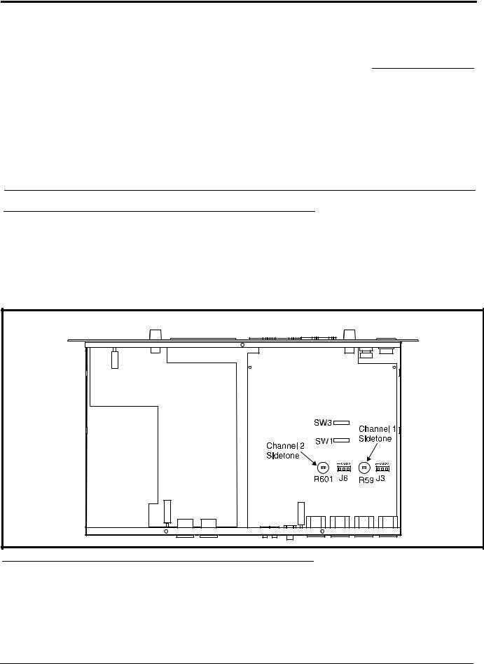
Configuration Pre-check
Before connecting the MS-2002 make sure it is properly configured for you intended usage. The locations of the configuration switches are shown in Figure 2.
To access internal switches, do the following:
>Remove three (3) screws from the top cover and three (3) screws from the bottom portion of each side.
FIGURE 2. Configuration Jumpers and Switches Location
9
Loading...