


TELEDYNE
HASTINGS
INSTRUMENTS
INSTRUCTION MANUAL
HPM-2002-OBE
VACUUM GAUGE
I S O 9 0 0 1
C E R T I F I E D
Manual Print History
The print history shown below lists the printing dates of all revisions and addenda created for this manual. The revision level letter increases alphabetically as the manual undergoes subsequent updates. Addenda, which are released between revisions, contain important change information that the user should incorporate immediately into the manual. Addenda are numbered sequentially. When a new revision is created, all addenda associated with the previous revision of the manual are incorporated into the new revision of the manual. Each new revision includes a revised copy of this print history page.
Revision D (Document Number 155-022002) |
......................................................................... February 2002 |
Revision E (Document Number 155-072002) ................................................................................... |
July 2002 |
Revision F (Document Number 155-082002) ............................................................................. |
August 2002 |
Revision G (Document Number 155-062004) ................................................................................. |
June 2004 |
Revision H (Document Number 155-082005) ............................................................................ |
August 2005 |
Revision J (Document Number 155-092007) ........................................................................ |
September 2007 |
Revision K (Document Number 155-062008).................................................................................. |
June 2008 |
Revision L (Document Number 155-112008) ........................................................................ |
November 2008 |
Revision M (Document Number 155-122008) ...................................................................... |
December 2008 |
Revision N (Document Number 155-082010) ............................................................................ |
August 2010 |
Revision P (Document Number 155-102011) ............................................................................ |
October 2011 |
Visit www.teledyne-hi.com for WEEE disposal guidance.
CAUTION:
CAUTION:
CAUTION:
The instruments described in this manual are available with multiple pin-outs. Ensure that all electrical connections are correct.
The instruments described in this manual are designed for INDOOR use only.
The instruments described in this manual are designed for Class 2 installations in accordance with IPC standards
Hastings Instruments reserves the right to change or modify the design of its equipment without any obligation to provide notification of change or intent to change.
HPM-2002-OBEVacuum Gauge |
Page 2 of 39 |
Table of Contents
1. GENERAL INFORMATION............................................................................................................................................ |
5 |
|
1.1. |
FEATURES: ............................................................................................................................................................. |
5 |
1.2. MODEL 2002 SENSORS........................................................................................................................................... |
5 |
|
1.3. HPM-2002-OBE ANALOG OUTPUT MODULE........................................................................................................ |
5 |
|
1.4. HPM-2002-OBE ANALOG OUTPUT (4-20MA) MODULE ....................................................................................... |
5 |
|
1.5. HPM-2002-OBE RS232/485 OUTPUT MODULE .................................................................................................... |
6 |
|
1.6. HPM-2002-OBE DEVICENET MODULE................................................................................................................. |
6 |
|
1.7. |
SPECIFICATIONS ..................................................................................................................................................... |
6 |
2. INSTALLATION.......................................................................................................................................................... |
7 |
|
2.1. |
RECEIVING INSPECTION ......................................................................................................................................... |
7 |
2.2. |
QUICK START......................................................................................................................................................... |
7 |
2.3. |
TRANSDUCER INSTALLATION................................................................................................................................. |
7 |
2.4. |
OBE MODULE INSTALLATION ............................................................................................................................... |
7 |
2.5. |
INITIAL OPERATION ............................................................................................................................................... |
8 |
3. OPERATING INFORMATION.................................................................................................................................. |
9 |
||
3.1. |
ANALOG OUTPUT (0-10V) ..................................................................................................................................... |
9 |
|
3.1.1. |
|
Overall Functional Description........................................................................................................................ |
9 |
3.1.2. High and Low Set Point Modes ........................................................................................................................ |
9 |
||
3.1.3. |
|
Run Mode ....................................................................................................................................................... |
10 |
3.1.4. |
|
Cal Mode ........................................................................................................................................................ |
10 |
3.1.5. |
|
GAS Mode....................................................................................................................................................... |
11 |
3.1.6. |
|
Analog Output (0-10V) ................................................................................................................................... |
11 |
3.2. |
ANALOG OUTPUT (4-20MA) ................................................................................................................................ |
13 |
|
3.2.1. |
|
Overall Functional Description...................................................................................................................... |
13 |
3.2.2. High and Low Set Point Modes ...................................................................................................................... |
13 |
||
3.2.3. |
|
Run Mode ....................................................................................................................................................... |
13 |
3.2.4. |
|
Cal Mode ........................................................................................................................................................ |
14 |
3.2.5. |
|
GAS Mode....................................................................................................................................................... |
15 |
3.2.6. |
|
Analog Output (4-20mA) ................................................................................................................................ |
15 |
3.3. |
RS232/485 WITH DISPLAY .................................................................................................................................. |
17 |
|
3.3.1. |
|
Overall Functional Description...................................................................................................................... |
17 |
3.3.2. |
|
COMMAND SYNTAX..................................................................................................................................... |
17 |
3.3.3. |
|
Interrogation Commands................................................................................................................................ |
18 |
3.3.4. |
|
Paramater Modification Commands .............................................................................................................. |
18 |
3.3.5. |
|
Calibration Adjustment Commands................................................................................................................ |
19 |
3.3.6. Reset / Restore Commands ............................................................................................................................. |
19 |
||
3.3.7. |
|
Device Status .................................................................................................................................................. |
20 |
3.3.8. |
|
Default RS232/485 Specifications .................................................................................................................. |
20 |
3.3.9. Modular Connector Pinout (R2-232) RJ-11 connector on left side................................................................ |
21 |
||
3.3.10. |
Modular Connector Pinout (RS-485)......................................................................................................... |
21 |
|
3.3.11. |
High and Low Set Point Modes ................................................................................................................. |
21 |
|
3.3.12. |
Run Mode................................................................................................................................................... |
22 |
|
3.3.13. |
Cal Mode ................................................................................................................................................... |
22 |
|
3.4. |
DEVICENET TM ..................................................................................................................................................... |
23 |
|
3.4.1. |
|
Overall Functional Description...................................................................................................................... |
23 |
3.4.2. |
|
DeviceNet description .................................................................................................................................... |
23 |
3.5. |
CALIBRATION OF THE HPM-2002-OBE............................................................................................................... |
24 |
|
3.5.1. |
|
Zero Coefficient Adjustment ........................................................................................................................... |
24 |
3.5.2. |
|
Midrange Coefficient Adjustment................................................................................................................... |
24 |
3.5.3. |
|
Atmosphere Coefficient Adjustment................................................................................................................ |
24 |
4. THEORY OF OPERATION |
..................................................................................................................................... 25 |
|
4.1.1. |
............................................................................................................................................................................. |
25 |
4.2. |
PIEZORESISTIVE SENSOR ...................................................................................................................................... |
26 |
4.3. |
PIRANI SENSOR .................................................................................................................................................... |
28 |
HPM-2002-OBEVacuum Gauge |
Page 3 of 39 |
|
|
4.4. |
DUAL SENSOR OPERATION .................................................................................................................................. |
30 |
5. |
TROUBLESHOOTING ............................................................................................................................................. |
32 |
|
|
5.1. ADVANCED SETUP GUIDE .................................................................................................................................... |
32 |
|
|
5.2. |
FREQUENTLY ASKED QUESTIONS ........................................................................................................................ |
34 |
6. |
WARRANTY .............................................................................................................................................................. |
36 |
|
|
6.1. |
WARRANTY REPAIR POLICY ................................................................................................................................ |
36 |
|
6.2. |
NON-WARRANTY REPAIR POLICY ....................................................................................................................... |
36 |
7. |
DIAGRAMS AND DRAWINGS ............................................................................................................................... |
37 |
|
HPM-2002-OBEVacuum Gauge |
Page 4 of 39 |

1. General Information
The Hastings HPM-2002-OBE is a small, low cost electronics module which provides the user with accurate vacuum measurements over a wide range of pressure. The HPM-2002-OBE uses the same rugged HPM-2002s transducer tube as the HPM-2002 bench top instrument. This tube features two sensors; a patented thin-film Pirani sensor and a piezoresistive sensor combined in a single tube with a matched EEPROM (Electrically Erasable/Programmable Read Only Memory).
The HPM-2002-OBE electronics module combined with the HPM-2002’s tube provides accurate vacuum measurement from 1x10⁻⁴ Torr to 1000 Torr. The HPM-2002-OBE is designed for quick, easy installation and will provide the user with long lasting, trouble free, reliable vacuum measurement.
1.1.Features:
•Low-Cost Electronics Module
•Wide Dynamic Range 1x10⁻⁴ Torr to 1000 Torr
•Combined Sensors in a Single Tube
•Input Voltage (11.5-30 VDC)
•Connector: 15-pin high-density male “D”
•Optional 4-digit LED Display
•Optional Outputs (Dual 0-10 volt analog or RS232/485)
1.2.Model 2002 Sensors
The Model 2002 transducer tube is comprised of an ion implanted piezoresistive, direct force sensor and a thin film Pirani type sensor. The Pirani sensing element is a Pt thin film serpentine element deposited on a 1 micron thick Si3N4 membrane. The membrane is peripherally supported by a Si box shaped die and is covered by a thick Si lid parallel to the membrane and open on two ends. The piezoresistive unit is an ion implanted Wheatstone bridge in a 50 micron thick Si membrane peripherally supported by a Si box shaped die which has been anodically bonded to a Pyrex substrate.
The dual sensor assembly is encased in a corrosion resistant 316 stainless steel tube shell. The durable tube design withstands high pressure (150 psig/10.2 bar) and high pressure surges. Since the Pirani sensor is miniaturized and employs a Pt thin film on a Si3N4 membrane (instead of a conventional long fragile wire), the transducer can withstand high levels of mechanical shock.
The Model 2002 is designed for fast response. The micro machined sensing elements have a very small mass and operate in a constant temperature (Pirani) and a constant current (piezo) feedback mode. This makes response time very fast as compared to other commercially available sensors which have to change the temperature of a significant mass to reflect pressure changes and have a large internal volume which must equalize in pressure with the system before the sensor can reach its final value. The transducer’s small internal volume (<1.5 cc) permits rapid pneumatic response to system pressure changes. Further, the small geometry of the transducer prevents thermal convection currents which allows the sensor to be mounted in any orientation without calibration shifts.
1.3. HPM-2002-OBE Analog Output Module
The analog output (0-10 V) module consists of a power conversion/sensor transducer board, microprocessor board and a user interface option board. Two 0-10 Volt linear outputs are generated for the user via the high-density 15-pin “D” connector. The first of these outputs covers the pressure range from 0 to 1024 Torr. The second output covers the range from 0 to 1000 mTorr. A four digit floating-point LED display is standard.
1.4. HPM-2002-OBE Analog Output (4-20mA) Module
(Identical to 1.3, except replace 0-10 V with 4-20 mA)
HPM-2002-OBEVacuum Gauge |
Page 5 of 39 |

1.5. HPM-2002-OBE RS232/485 Output Module
The RS232/485 module consists of a power conversion/sensor transducer board, microprocessor board and a user interface option board. Serial communication is conducted via an RJ-11 type connector. With RS232 option (EIA-232 Rev. E) communication can easily be established between the module and the serial port of a PC. The RS485 option allows the user to address multiple units and allows operation at distances of up to 4000 feet. The RS232/485 module includes a four digit floating-point LED display.
1.6. HPM-2002-OBE DeviceNet Module
The DeviceNet module consists of a power conversion/sensor transducer board, microprocessor board and a user interface option board. All communication is conducted via a 5-pin “Micro” style with center pin, male pin contacts. The module has passed the ODVA DeviceNet test and conforms to the vacuum/pressure gauge device profile, an Electronic Data Sheet (EDS) with limited features is also available upon request.
1.7. Specifications
Measuring range ............................................................................................................. |
1x10⁻⁴ to 10+3 Torr |
.............................................................................................................................. |
1.3x10⁻⁴ to 1.3x10+3 mbar |
Accuracy (N2, T=23°C) .................................................................. |
+ 20% of reading (1 x10⁻³ to 50 Torr) |
............................................................................................................ |
+ 1.5% of reading (50 to 1000 Torr) |
Ambient temperature operating range........................................................................................... |
0° to 50°C |
Process control ......................................................... |
2 TTL outputs (1 TTL remote zero command input) |
Digital readout....................................................................................................................... |
Four digit LED |
Equipment operating ranges ....................................................................................................... |
12-30 VDC |
Transducer mounting ............................................................................ |
Any position without recalibration. |
Transducer internal volume .............................................................................................................. |
< 1.5 cc |
Wetted material ...................................................................................................... |
Au, Si3N4, Si, PyrexTM, |
.................................................................................................................... |
KovarTM, 316 stainless steel and |
.................................................................................................... |
High Temp/Low Outgassing UHV Epoxy |
Weight (OBE & HPM-2002s tube) .......................................................................... |
12 oz (1/8” NPT tube) |
Calibrated for nitrogen ..................................................... |
Conversion Factors for other gases are selectable |
Burst Pressure (Tube)...................................................................................................................... |
150 psig |
Proof Pressure (*) .............................................................................................................................. |
30 psig |
Nominal Operating Pressure (Tube) .............................................................................. |
1x10⁻⁴ to 10+3 Torr |
Input Operating Range ........................................................................................................ |
11.5 to 30 VDC |
Input Power.................................................................................................................... |
24 VDC @ 125 mA |
* Maximum pressure above which may cause permanent damage.
HPM-2002-OBEVacuum Gauge |
Page 6 of 39 |

2. Installation
This section is designed to assist in getting a new pressure gauge into operation as quickly and easily as possible. Please read the following instructions thoroughly before installing the instrument.
2.1. Receiving Inspection
Carefully unpack the Hastings Model HPM-2002-OBE Instrument (part # HPM-2002-OBE), and transducer tube (part #HPM 2002s-xx). Inspect all items for any obvious signs of damage due to shipment. Immediately advise the carrier who delivered the shipment if any damage is suspected.
Compare each component shipped against the packing list. Ensure that all parts are present (i.e. transducer, electronics module, hardware, etc.). Optional equipment or accessories will be listed separately on the packing list.
2.2.Quick Start
•Unpack and inspect all items for any obvious signs of damage due to shipment. Immediately advise the carrier who delivered the shipment if any damage is suspected.
•Wire the 15-pin “D” connector according to cable pinout (see Table below) using 24 AWG or other suitable wire.
•Using a unipolar DC Power Supply, set the desired operating voltage within the range of 12 VDC to 30 VDC.
•Connect the HPM-2002-OBE module to the HPM-2002s transducer tube.
•Note that the connector is keyed.
•A finger tight connection is all that is required for adequate operation.
•Transducer tube may be installed in any orientation. However, if condensation is likely to occur, then the tube port should be orientated downward.
•When installing 1/8” NPT style transducer tube, use the 7/16” wrench flats.
•Attach cable.
•With the vacuum chamber at atmosphere, turn on the power supply (typically +24 VDC. Gauge is now reading pressure.
•For best accuracy, the gauge should now be zeroed. Pump the vacuum system down to low (10-6 Torr) pressure if possible. Ideally the gauge should be operated in this condition for one hour before setting the “Zero”.
•To set the “Zero”, place the HPM-2002-OBE in the “CAL” mode by using the “SELECT” button.
•Using a small flat head screwdriver, rotate the “ADJUST” rotary encoder until the unit flashes between “0.0” and “-0.0”.
•Return to the “RUN” mode by using the “SELECT” button
2.3.Transducer Installation
The transducer tube may be installed in any orientation. Although the transducer tube is rugged and will perform well in many harsh environments, the tube should be installed in a clean and careful manner. The tube is configured with the vacuum fitting requested. If your vacuum environment is highly contaminated or has unique fitting requirements, a Hastings filter or special adapter may be needed. Please contact the Hastings Instruments Sales Department for assistance in your system configuration.
2.4.OBE Module Installation
•Environment:
•Indoor use
•Altitude up to 2000 meters
•Operating temperature range from 5 to 40°C
HPM-2002-OBEVacuum Gauge |
Page 7 of 39 |

•Maximum relative humidity: 80% for temperatures up to 31°C decreasing linearly to 50% relative humidity at 40°C.
•Installation category II
HPM-2002-OBE
CABLE PINOUT
|
Analog Ouput |
Analog Ouput |
Digital Output |
|
Pin |
0-10 Volt |
4-20 mA |
RS232/485 |
|
No. |
||||
|
|
|
||
|
|
|
|
|
1 |
High Setpoint Output |
High Setpoint Output |
High Setpoint Output |
|
2 |
Low Setpoint Output |
Low Setpoint Output |
Low Setpoint Output |
|
3 |
Power Input (+12 to 30 VDC) |
Power Input (+12 to 30 VDC) |
Power Input (+12 to 30 VDC) |
|
4 |
Power Return |
Power Return |
Power Return |
|
5 |
Channel 1 Vout (+) |
Channel 1 Iout (-) |
NC |
|
6 |
Analog Return |
Analog Shield |
NC |
|
7 |
Channel 2 Vout (+) |
Channel 2 Iout (-) |
NC |
|
8 |
Digital Ground |
Digital Ground |
Digital Ground |
|
9 |
Remote Zero |
Remote Zero |
Remote Zero |
|
10 |
NC |
Channel 1 Iout (+) |
NC |
|
11 |
NC |
Channel 2 Iout (+) |
NC |
|
12 |
NC |
NC |
NC |
|
13 |
NC |
NC |
NC |
|
14 |
Rx In (Internal Use) |
Rx In (Internal Use) |
NC |
|
15 |
Tx Out (Internal Use) |
Tx Out (Internal Use) |
NC |
2.5. Initial Operation
Upon applying power to the control unit a pressure measurement will be given in Torr for nitrogen. However, it is recommended that the user follow the instructions for zeroing and adjusting the output at atmosphere.
HPM-2002-OBEVacuum Gauge |
Page 8 of 39 |
3. Operating Information
This section contains information on operating the HPM-2002-OBE in any of its various configurations. Refer to the appropriate section for information on the mode in use.
3.1. Analog Output (0-10V)
3.1.1.Overall Functional Description
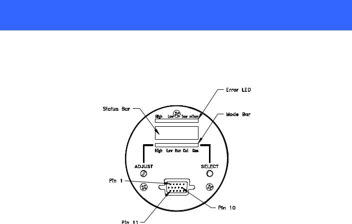
The status bar gives information about the condition of the HPM-2002-OBE. High and Low indicate whether the set points are activated. ERROR indicates if there was a problem downloading the EEPROM. Torr and mTorr indicate what pressure regime the gauge is measuring.
The mode bar indicates which mode has been selected. The HPM-2002-OBE has five modes which the user may enter. This is similar to the six modes which can be entered in the bench top/panel mounted HPM2002, there is no interlock feature; when the user changes the setting within a mode, any adjustments that have been made will be permanent once the mode is exited. To exit without making changes permanent, the user must turn the power off.
3.1.2.High and Low Set Point Modes
The HPM-2002-OBE provides TTL outputs for process control. These signals are available on the 15-pin connector (see previous table in Section 2.4).
To view the High set point, place the HPM-2002-OBE in the High mode by pressing the SELECT button until the High mode light is illuminated. The display then shows the set point selected. During normal operation the alarm light will illuminate and the TTL output (pin # 1) will go high (+5V) if the pressure exceeds the set point.
Similarly, to view the Low set point, place the HPM-2002-OBE in the Low mode by pressing the SELECT button until the Low mode light is illuminated. The display then shows the set point selected. During normal operation the alarm light will illuminate and the TTL output (pin # 2) will go high (+5V) if the pressure becomes less than the set point.
To adjust a setpoint, place the HPM-2002-OBE in either setpoint mode (High or Low). Next, use the ADJUST rotary encoder until the desired setpoint is displayed. Finally, place the HPM-2002-OBE back in the Run mode. The new setpoints are now stored in the HPM-2002-OBE’s memory.
HPM-2002-OBEVacuum Gauge |
Page 9 of 39 |
3.1.3.Run Mode
The HPM-2002-OBE will automatically enter the Run mode upon start-up. This is the mode for normal operation and the mode in which the instrument will spend most of its time. In the Run mode the HPM-2002- OBE will continuously monitor the pressure, update the alarm conditions, and update the display about ten times a second.
3.1.4.Cal Mode
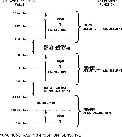
Optimal performance of the HPM-2002-OBE is achieved by performing in situ adjustments to the calibration coefficients in the Cal mode. There are three calibration coefficients. These are the zero coefficient, the midrange coefficient, and the atmosphere coefficient. Once a tube has been fully calibrated the midrange coefficient should never need further adjustment, but it may be helpful to adjust the zero coefficient or the atmosphere coefficient under certain circumstances. The CAL MODE presupposes that the operator is applying a known pressure of the correct gas composition (see GAS MODE). The factory calibration points are 800 Torr, 7 Torr, and < 10-6 Torr. The user’s calibration points are not required to be exactly those values, but should be somewhat close, and must be within the ranges shown in the following figure. The HPM-2002-OBE detects the voltage signal within the sensor tube, which is converted and displayed as a pressure reading. The resulting pressure reading determines which of the three coefficients will be adjusted.
The operator action is the same for adjustment of all three of the coefficients, except that he must apply the proper calibration pressures according to the calibration point he is about to adjust. To adjust a calibration
HPM-2002-OBEVacuum Gauge |
Page 10 of 39 |
coefficient, place the HPM-2002-OBE in the Cal mode using the SELECT button. Then turn the ADJUST rotary encoder. The Cal light will begin to flash during adjustment and will continue to flash until the Cal mode is exited using the SELECT button.
To perform a full calibration on the HPM-2002-OBE, first use the Zero Coefficient Adjustment Procedure. Followed by the Midrange Coefficient Adjustment Procedure, and finally perform the Atmosphere Coefficient Adjustment Procedure. Sensor Coefficients are stored in the Sensor’s EEPROM upon exiting the Cal mode.
3.1.5.GAS Mode
The HPM-2002-OBE can provide true pressure measurements in many gas environments. At pressure levels where the direct force piezoresistive sensor is operative, the instrument is gas composition independent and measures the true pressure regardless of gas composition. The Pirani is gas composition sensitive so the actual composition must be known and the Pirani calibrated in that gas. When the vacuum system’s gas composition is dominated by a single gas species (for example, during system venting with an inert gas), the user can enter a gas selection into the HPM-2002-OBE by rotating the ADJUST rotary encoder. To view the gas selection, depress the SELECT button until the GAS light is illuminated. The number on the display corresponds to the gas. See the table below.
Gas Selection Table
Gas Mode |
Gas |
Displayed Number |
|
|
|
00 |
Nitrogen |
|
|
01 |
Argon |
|
|
02 |
Helium |
|
|
03 |
Water Vapor |
|
|
04 |
Custom |
|
|
3.1.6.Analog Output (0-10V)
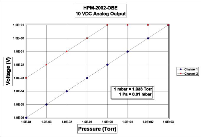
The dual (0 - 10V) output option board provides voltage outputs proportional to the HPM-2002-OBE’s pressure reading. The first channel (pin 5) corresponds to the higher-pressure range (0 - 1024 Torr). The second channel (pin 7) corresponds to the lower pressure range (0 - 1000 mTorr). The equation below gives the output voltage on the pressure:
V (channel1) = pressure100
V (channel2) = 10× pressure
Where V(channel 1) is the voltage between pins 5 and 6, V(channel 2) is the voltage between pins 7 and 6, and the pressure is indicated in Torr.
HPM-2002-OBEVacuum Gauge |
Page 11 of 39 |
HPM-2002-OBEVacuum Gauge |
Page 12 of 39 |
 Loading...