


INSTRUCTION MANUAL
Model 9110T
Nitrogen Oxides Analyzer
P/N M9110T
DATE 11/15/13
TELEDYNE ELECTRONIC TECHNOLOGIES
Analytical Instruments
16830 Chestnut Street
City of Industry, CA 91748
Telephone: (626) 934-1500
Fax: (626) 961-2538
Web: www.teledyne-ai.com
Teledyne Analytical Instruments |
ii |

Model 9110T NOx Analyzer
Copyright © 2013 Teledyne Analytical Instruments
All Rights Reserved. No part of this manual may be reproduced, transmitted, transcribed, stored in a retrieval system, or translated into any other language or computer language in whole or in part, in any form or by any means, whether it be electronic, mechanical, magnetic, optical, manual, or otherwise, without the prior written consent of Teledyne Analytical Instruments, 16830 Chestnut Street, City of Industry, CA 91748.
Warranty
This equipment is sold subject to the mutual agreement that it is warranted by us free from defects of material and of construction, and that our liability shall be limited to replacing or repairing at our factory (without charge, except for transportation), or at customer plant at our option, any material or construction in which defects become apparent within one year from the date of shipment, except in cases where quotations or acknowledgements provide for a shorter period. Components manufactured by others bear the warranty of their manufacturer. This warranty does not cover defects caused by wear, accident, misuse, neglect or repairs other than those performed by Teledyne or an authorized service center. We assume no liability for direct or indirect damages of any kind and the purchaser by the acceptance of the equipment will assume all liability for any damage which may result from its use or misuse.
We reserve the right to employ any suitable material in the manufacture of our apparatus, and to make any alterations in the dimensions, shape or weight of any parts, in so far as such alterations do not adversely affect our warranty.
Important Notice
This instrument provides measurement readings to its user, and serves as a tool by which valuable data can be gathered. The information provided by the instrument may assist the user in eliminating potential hazards caused by his process; however, it is essential that all personnel involved in the use of the instrument or its interface be properly trained in the process being measured, as well as all instrumentation related to it.
The safety of personnel is ultimately the responsibility of those who control process conditions. While this instrument may be able to provide early warning of imminent danger, it has no control over process conditions, and it can be misused. In particular, any alarm or control systems installed must be tested and understood, both as to how they operate and as to how they can be defeated. Any safeguards required such as locks, labels, or redundancy, must be provided by the user or specifically requested of Teledyne at the time the order is placed.
Therefore, the purchaser must be aware of the hazardous process conditions. The purchaser is responsible for the training of personnel, for providing hazard warning methods and instrumentation per the appropriate standards, and for ensuring that hazard warning devices and instrumentation are maintained and operated properly.
Teledyne Analytical Instruments, the manufacturer of this instrument, cannot accept responsibility for conditions beyond its knowledge and control. No statement expressed or implied by this document or any information disseminated by the manufacturer or its agents, is to be construed as a warranty of adequate safety control under the user’s process conditions.
Trademarks
All trademarks, registered trademarks, brand names or product names appearing in this document are the property of their respective owners and are used herein for identification purposes only.
Teledyne Analytical Instruments |
ii |
Model 9110TH NOx Analyzer |
Specific Configuration |
INFORMATION ABOUT THE SPECIFIC CONFIGURATION OF YOUR MODEL 9110T NOX ANALYZER
Note: All instruments must include the standard hardcopy manual.
SELECTED VERSIONS OF THE MODEL 9110T
Model 9110T— Standard Touch Screen Version
This Model 9110E NOx Analyzer is a touch screen version designed for analyzing the NOx concentration in a background gas specified by the customer. It has a minimum settable range of 0-50 ppb and a maximum settable range of 0-10 ppm. The standard version is designed for ambient pressure applications. The analyzer may have one or two analysis ranges with or without auto-ranging as listed below. It includes an internal Moly converter and an external pump. Alarm relays are optional and if included, that option will be checked below.
Model 9110TH — High Range Touch Screen Version
The Model 9110EH NOx Analyzer is a touch screen version designed for analyzing higher NOx concentration (from 0-5 ppm to 0-5000 ppm) than the standard model. It includes an internal Hicon converter and an external pump. Alarm relays are optional and if included, that option will be checked below. There is no internal zero/span gas/oven option available for this model. The analyzer may have one or two analysis ranges with or without autoranging as listed below.
This version is available with internal or external Hicon or Moly converters.
Model 9110TM — Mid-Range Touch Screen Version
The Model 9110EA NOx Analyzer is a touch screen version designed for analyzing a mid-range NOx concentration. It has a minimum settable range of 0-1 ppm and a maximum settable range of 0-200 ppm. t includes an internal Moly converter and an external pump. Alarm relays are optional and if included, that option will be checked below. There is no internal zero/span gas/oven option available for this model. The analyzer may have one or two analysis ranges with or without autoranging as listed below.
This model is similar to the EH version but does not have a sample bypass line. An optional paramagnetic oxygen sensor is available for oxygen analysis in this version.
Converter Options
The 9110 is equipped with an internal Hicon thermal converter as standard equipment. Other converters are available for the EH version as follows:
Internal Hicon (standard) |
External Hicon (2nd set of rack mounts req’d) |
Internal Moly |
External Moly (2nd set of rack mounts req’d) |
Teledyne Analytical Instruments |
iii |
Model 9110T NOx Analyzer Specific Configuration
Power Requirements
This Model 9110E is configured to operate from the following AC Power source:
100-120 VAC 60 Hz |
220-240 VAC 60 Hz |
100V 60 Hz |
100-120 VAC 50 Hz |
220-240 VAC 50 Hz |
100V 50 Hz |
Analog Output Signals
Analog output signals are available at A1, A2, and A3 on the rear panel. This instrument is configured with the following analog outputs:
A1(NOx): 4-20 mA |
|
|
A2 |
(NO): 0-5 V |
A2(NO): 4-20 mA |
A3 |
(NO2): 0-5 V |
A2(NO2): 4-20 mA |
Range Mode
The analyzer can be designed with a single or dual analysis ranges with auto-ranging or dual independent ranges. This analyzer is configured with the following range mode:
Single Range: |
|
|
|||
Dual Range/Auto-ranging: |
Dual Range/Independent: |
||||
Low Range: |
Low Range: |
||||
High Range: |
|
|
High Range: |
||
|
|||||
|
|
|
|
|
Gas: |
Selected Options for the Model 9110T
Mounting Options

 19” rack mounting with 26” sliders with ears
 19” rack mounting with ears only
Pump Mounting Options

 None
None

 Rack mounting hardware
Rear Panel Gas Fittings

 1/4” SS Standard

 6 mm SS Optional
Teledyne Analytical Instruments |
iv |

Model 9110TH NOx Analyzer |
Specific Configuration |
Valve Options
No Valves

 Internal SS Zero/Span Valves

 Second Range Span Valve

 Internal Zero/Span Valves with Oven (Not available for 9110EH/EM)

 Internal Zero/Span Valves with Oven and Permeation Tube (Not available for 9110EH)
The permeation tube option installed depends on the sample gas and the effusion rate. The specific permeation tube in this instrument is listed below:
Permeation tube Installed:
Alarm Relay Option
This option includes two concentration alarm relays.
Oxygen Sensor
This analyzer is equipped with a paramagnetic oxygen sensor for measuring the oxygen concentration over the range of 0-25%
Gas Conditioner
A gas conditioner/dryer permeation gas exchange tube is installed for removing H2O and ammonia from the sample stream. This item is required for EN certificatation.
Oxygenator
For applications where background gas less than 2% oxygen and using a Moly converter.
Remote Operation for Purged Enclosure
The operator interface is duplicated with switches mounted on the front door of the enclosure allowing operation without compromising purge integrity.
Background Gas:
Notes:
Teledyne Analytical Instruments |
v |

Model 9110T NOx Analyzer |
Specific Configuration |
This page intentionally left blank..
Teledyne Analytical Instruments |
vi |
Model 9110TH NOx Analyzer |
Safety Messages |
SAFETY MESSAGES
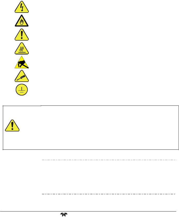
Important safety messages are provided throughout this manual for the purpose of avoiding personal injury or instrument damage. Please read these messages carefully. Each safety message is associated with a safety alert symbol, and are placed throughout this manual and inside the instrument. The symbols with messages are defined as follows:
WARNING: Electrical Shock Hazard
HAZARD: Strong oxidizer
GENERAL WARNING/CAUTION: Read the accompanying message for specific information.
CAUTION: Hot Surface Warning
Do Not Touch: Touching some parts of the instrument without protection or proper tools could result in damage to the part(s) and/or the instrument.
Technician Symbol: All operations marked with this symbol are to be performed by qualified maintenance personnel only.
Electrical Ground: This symbol inside the instrument marks the central safety grounding point for the instrument.
CAUTION
GENERAL SAFETY HAZARD
The T100 Analyzer should only be used for the purpose and in the manner described in this manual. If you use the T100 in a manner other than that for which it was intended, unpredictable behavior could ensue with possible hazardous consequences.
NEVER use any gas analyzer to sample combustible gas(es).
Note |
Technical Assistance regarding the use and maintenance of the 9110T or |
|
any other Teledyne product can be obtained by contacting Teledyne’s |
||
|
||
|
Customer Service Department: |
|
|
Phone: 626-934-1500 |
|
|
Email: ask_tai@teledyne.com |
|
|
or by accessing various service options on our website at |
|
|
http://www.teledyne-ai.com/. |
Teledyne Analytical Instruments |
vii |
Model 9110T NOx Analyzer |
Safety Messages |
CONSIGNES DE SÉCURITÉ
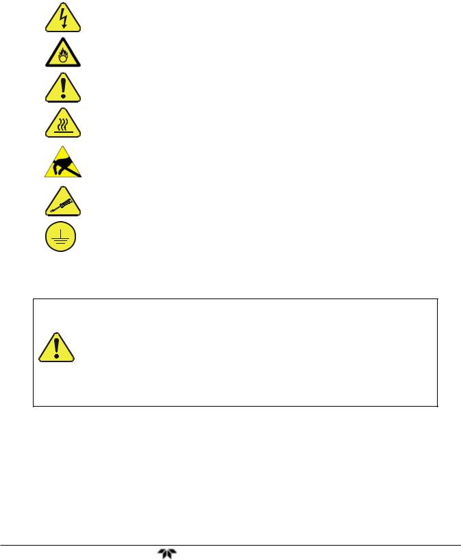
Des consignes de sécurité importantes sont fournies tout au long du présent manuel dans le but d’éviter des blessures corporelles ou d’endommager les instruments. Veuillez lire attentivement ces consignes. Chaque consigne de sécurité est représentée par un pictogramme d’alerte de sécurité; ces pictogrammes se retrouvent dans ce manuel et à l’intérieur des instruments. Les symboles correspondent aux consignes suivantes :
AVERTISSEMENT : Risque de choc électrique
DANGER : Oxydant puissant
AVERTISSEMENT GÉNÉRAL / MISE EN GARDE : Lire la consigne complémentaire pour des renseignements spécifiques
MISE EN GARDE : Surface chaude
Ne pas toucher : Toucher à certaines parties de l’instrument sans protection ou sans les outils appropriés pourrait entraîner des dommages aux pièces ou à l’instrument.
Pictogramme « technicien » : Toutes les opérations portant ce symbole doivent être effectuées uniquement par du personnel de maintenance qualifié.
Mise à la terre : Ce symbole à l’intérieur de l’instrument détermine le point central de la mise à la terre sécuritaire de l’instrument.
MISE EN GARDE
Cet instrument doit être utilisé aux fins décrites et de la manière décrite dans ce manuel. Si vous utilisez cet instrument d’une autre manière que celle pour laquelle il a été prévu, l’instrument pourrait se comporter de façon imprévisible et entraîner des conséquences dangereuses.
NE JAMAIS utiliser un analyseur de gaz pour échantillonner des gaz combustibles!
Teledyne Analytical Instruments |
viii |
Model 9110TH NOx Analyzer |
Safety Messages |
ABOUT THIS MANUAL
This manual describes operation, specifications, and maintenance for the Model 9110T.
In addition this manual contains important SAFETY messages for this instrument. It is strongly recommended that you read that operation manual in its entirety before operating the instrument.
ORGANIZATION
This manual is divided among three main parts and a collection of appendices at the end.
Part I contains introductory information that includes an overview of the analyzer, specifications, descriptions of the available options, installation and connection instructions, and the initial calibration and functional checks.
Part II comprises the operating instructions, which include initial functional checks and calibration, basic, advanced and remote operation, advanced calibration, diagnostics, testing, and ends with specifics of calibrating for use in EPA monitoring.
Part III provides detailed technical information, starting with maintenance, troubleshooting and service with Frequently Asked Questions (FAQs), followed by principles of operation, and a glossary. It also contains a special section dedicated to providing information about electro-static discharge and protecting against its consequences.
The appendices at the end of this manual provide support information such as, version-specific software documentation, lists of spare parts and recommended stocking levels, and schematics.
CONVENTIONS USED
In addition to the safety symbols as presented in the Important Safety Information page, this manual provides special notices related to the safety and effective use of the analyzer and other pertinent information.
Special Notices appear as follows:
ATTENTION |
COULD DAMAGE INSTRUMENT AND VOID WARRANTY |
|
This special notice provides information to avoid damage to your |
|
instrument and possibly invalidate the warranty. |
IMPORTANT |
IMPACT ON READINGS OR DATA |
|
Could either affect accuracy of instrument readings or cause loss of data. |
Note |
Pertinent information associated with the proper care, operation or |
|
maintenance of the analyzer or its parts. |
Teledyne Analytical Instruments |
ix |

Model 9110T NOx Analyzer |
Safety Messages |
This page intentionally left blank..
Teledyne Analytical Instruments |
x |
Model 9110TH NOx Analyzer Table of Contents
TABLE OF CONTENTS
Information About the Specific Configuration of Your Model 9110T NOX Analyzer |
..............................................................iii |
||
Mounting Options .............................................................................................................................................................. |
|
iv |
|
Pump Mounting Options .................................................................................................................................................... |
iv |
||
Rear |
Panel Gas Fittings.................................................................................................................................................... |
iv |
|
Safety Messages.................................................................................................................................................................... |
|
vii |
|
About This Manual ................................................................................................................................................................. |
|
ix |
|
PART I |
GENERAL INFORMATION.................................................................................................................................... |
21 |
|
1. Introduction, Features and Options ........................................................................................................................................ |
23 |
||
1.1. Overview ........................................................................................................................................................................ |
|
23 |
|
1.2. Features ......................................................................................................................................................................... |
|
23 |
|
1.3. Documentation ............................................................................................................................................................... |
|
24 |
|
1.4. Options........................................................................................................................................................................... |
|
24 |
|
2. Specifications, Approvals, & Compliance............................................................................................................................... |
27 |
||
2.1. Specifications ................................................................................................................................................................. |
|
27 |
|
2.2. EPA Equivalency Designation ........................................................................................................................................ |
28 |
||
2.3. Approvals and Certifications........................................................................................................................................... |
29 |
||
2.3.1. Safety ..................................................................................................................................................................... |
|
29 |
|
2.3.2. EMC........................................................................................................................................................................ |
|
29 |
|
2.3.3. Other Type Certifications ........................................................................................................................................ |
29 |
||
3. Getting Started |
31 |
|
|
3.1. Unpacking the 9110T Analyzer ...................................................................................................................................... |
31 |
||
3.1.1. Ventilation Clearance.............................................................................................................................................. |
32 |
||
3.2. Instrument Layout........................................................................................................................................................... |
|
32 |
|
3.2.1. Front Panel ............................................................................................................................................................. |
|
33 |
|
3.2.2. Rear Panel.............................................................................................................................................................. |
|
37 |
|
3.2.3. Internal Chassis Layout .......................................................................................................................................... |
38 |
||
3.3. Connections and Setup .................................................................................................................................................. |
41 |
||
3.3.1. Electrical Connections ............................................................................................................................................ |
41 |
||
3.3.2. Pneumatic Connections.......................................................................................................................................... |
55 |
||
3.4. Startup, Functional Checks, and Initial Calibration ......................................................................................................... |
74 |
||
3.4.1. Start Up .................................................................................................................................................................. |
|
74 |
|
3.4.2. Warning Messages................................................................................................................................................. |
75 |
||
3.4.3. Functional Checks .................................................................................................................................................. |
77 |
||
3.4.4. Initial Calibration ..................................................................................................................................................... |
77 |
||
3.4.4.1. Interferents |
.......................................................................................................................................................... |
78 |
|
PART II – OPERATING INSTRUCTIONS............................................................................................................................ |
85 |
||
4. Overview of Operating Modes................................................................................................................................................ |
87 |
||
4.1. Sample Mode ................................................................................................................................................................. |
|
88 |
|
4.1.1. Test Functions ........................................................................................................................................................ |
88 |
||
4.1.2. Warning Messages................................................................................................................................................. |
91 |
||
4.2. Calibration Mode ............................................................................................................................................................ |
|
92 |
|
4.3. Setup Mode .................................................................................................................................................................... |
|
92 |
|
4.3.1. Password Security.................................................................................................................................................. |
93 |
||
4.3.2. Primary Setup Menu ............................................................................................................................................... |
93 |
||
4.3.3. Secondary Setup Menu (SETUP MORE)............................................................................................................ |
93 |
||
5. Setup Menu |
95 |
|
|
5.1. SETUP CFG: Configuration Information .................................................................................................................... |
95 |
||
5.2. SETUP ACAL: Automatic Calibration Option .............................................................................................................. |
95 |
||
5.3. SETUP DAS: Internal Data Acquisition System.......................................................................................................... |
95 |
||
5.4. SETUP RNGE: Analog Output Reporting Range Configuration ................................................................................. |
96 |
||
5.4.1. 9110T Physical Ranges.......................................................................................................................................... |
96 |
||
5.4.2. 9110T Analog Output Reporting Ranges................................................................................................................ |
96 |
||
5.4.3. SETUP RNGE MODE.................................................................................................................................... |
98 |
||
5.5. SETUP PASS: Password Protection........................................................................................................................ |
106 |
||
5.6. SETUP CLK: Setting the Internal Time-of-Day Clock .............................................................................................. |
108 |
||
5.6.1. Setting the Time of Day ........................................................................................................................................ |
108 |
||
5.6.2. Adjusting the Internal Clock’s Speed .................................................................................................................... |
109 |
||
5.7. SETUP COMM: Communications Ports................................................................................................................... |
110 |
||
5.7.1. ID (Machine Identification) .................................................................................................................................... |
110 |
||
5.7.2. INET (Ethernet) .................................................................................................................................................... |
111 |
||
5.7.3. COM1[COM2] (Mode, Baude Rate and Test Port) ............................................................................................... |
111 |
||
5.8. SETUP VARS: Variables Setup and Definition ........................................................................................................ |
111 |
||
Teledyne Analytical Instruments |
11 |

Model 9110T NOx Analyzer |
Table of Contents |
|
||
5.9. SETUP Diag: Diagnostics Functions........................................................................................................................ |
|
114 |
||
5.9.1. Signal I/O.............................................................................................................................................................. |
|
|
116 |
|
5.9.2. Analog Output (DIAG AOUT)................................................................................................................................ |
|
117 |
||
5.9.3. Analog I/O Configuration (DIAG AIO) ................................................................................................................... |
|
117 |
||
5.9.4. Test Chan Output (Selecting a Test Channel Function for Output A4) ................................................................. |
|
132 |
||
5.9.5. Optic Test ............................................................................................................................................................. |
|
|
133 |
|
5.9.6. Electrical Test ....................................................................................................................................................... |
|
134 |
||
5.9.7. Ozone Gen Override............................................................................................................................................. |
|
134 |
||
5.9.8. Flow Calibration.................................................................................................................................................... |
|
134 |
||
6. Communications Setup and Operation ................................................................................................................................ |
|
135 |
||
6.1. Data Terminal / Communication Equipment (DTE DEC).............................................................................................. |
|
135 |
||
6.2. Communication Modes, Baud Rate and Port Testing................................................................................................... |
|
135 |
||
6.2.1. Communication Modes ......................................................................................................................................... |
|
135 |
||
6.2.2. Com Port Baud Rate............................................................................................................................................. |
|
138 |
||
6.2.3. Com Port Testing.................................................................................................................................................. |
|
138 |
||
6.3. RS-232 ......................................................................................................................................................................... |
|
|
139 |
|
6.4. RS-485 (Option) ........................................................................................................................................................... |
|
|
140 |
|
6.5. Ethernet........................................................................................................................................................................ |
|
|
140 |
|
6.5.1. Configuring Ethernet Communication Manually (Static IP Address)..................................................................... |
|
140 |
||
6.5.2. Configuring Ethernet Communication Using Dynamic Host Configuration Protocol (DHCP)................................ |
143 |
|||
6.6. USB Port for Remote Access ....................................................................................................................................... |
|
147 |
||
6.7. Communications Protocols........................................................................................................................................... |
|
149 |
||
6.7.1. MODBUS.............................................................................................................................................................. |
|
|
149 |
|
6.7.2. Hessen ................................................................................................................................................................. |
|
|
151 |
|
7. Data Acquisition System (DAS) and APICOM ..................................................................................................................... |
|
163 |
||
7.1. DAS Structure .............................................................................................................................................................. |
|
|
164 |
|
7.1.1. DAS Channels ...................................................................................................................................................... |
|
164 |
||
7.1.2. Viewing DAS Data and Settings ........................................................................................................................... |
|
168 |
||
7.1.3. Editing DAS Data Channels.................................................................................................................................. |
|
169 |
||
7.2. Remote DAS Configuration .......................................................................................................................................... |
|
181 |
||
7.2.1. DAS Configuration via APICOM ........................................................................................................................... |
|
181 |
||
7.2.2. DAS Configuration via Terminal Emulation Programs .......................................................................................... |
|
183 |
||
8. Remote Operation |
185 |
|
|
|
8.1. Computer Mode............................................................................................................................................................ |
|
|
185 |
|
8.1.1. Remote Control via APICOM................................................................................................................................ |
|
185 |
||
8.2. Interactive Mode........................................................................................................................................................... |
|
|
185 |
|
8.2.1. Remote Control via a Terminal Emulation Program.............................................................................................. |
|
185 |
||
8.3. Remote Access by Modem........................................................................................................................................... |
|
188 |
||
8.4. Password Security for Serial Remote Communications ............................................................................................... |
|
191 |
||
9. Calibration Procedures 193 |
|
|
|
|
9.1. Before Calibration......................................................................................................................................................... |
|
|
194 |
|
9.1.1. Required Equipment, Supplies, and Expendables................................................................................................ |
|
194 |
||
9.1.2. Calibration Gases ................................................................................................................................................. |
|
195 |
||
9.1.3. Data Recording Devices ....................................................................................................................................... |
|
196 |
||
9.1.4. NO2 Conversion Efficiency (CE) ........................................................................................................................... |
|
197 |
||
9.2. Manual Calibration Checks and Calibration of the 9110T Analyzer in its Base Configuration...................................... |
|
197 |
||
9.2.1. Setup for Basic Calibration Checks and Calibration of the 9110T analyzer.......................................................... |
|
197 |
||
9.2.2. Performing a Basic Manual Calibration Check ..................................................................................................... |
|
199 |
||
9.2.3. Performing a Basic Manual Calibration................................................................................................................. |
|
199 |
||
9.3. Manual Calibration with the Internal Span Gas Generator ........................................................................................... |
|
202 |
||
9.3.1. Performing “Precision” Manual Calibration when Internal Span Gas (IZS) Generator Option is Present ............. |
202 |
|||
9.3.2. Setup for Calibration with the Internal Span Gas Generator................................................................................. |
|
203 |
||
9.3.3. CAL On NO2 Feature............................................................................................................................................ |
|
203 |
||
9.3.4. Performing a Manual Calibration Check with the Internal Span Gas Generator ................................................... |
|
205 |
||
9.3.5. Performing a Manual Calibration with the Internal Span Gas Generator .............................................................. |
|
206 |
||
9.4. Manual Calibration and Cal Checks with the Valve Options Installed .......................................................................... |
|
209 |
||
9.4.1. Setup for Calibration Using Valve Options............................................................................................................ |
|
209 |
||
9.4.2. Manual Calibration Checks with Valve Options Installed ...................................................................................... |
|
210 |
||
9.4.3. Manual Calibration Using Valve Options .............................................................................................................. |
|
211 |
||
9.5. Automatic Zero/Span Cal/Check (AutoCal) .................................................................................................................. |
|
213 |
||
9.5.1. SETUP ACAL: Programming and AUTO CAL Sequence ................................................................................ |
|
216 |
||
9.6. Calibration Quality Analysis.......................................................................................................................................... |
|
219 |
||
9.7. Gas Flow Calibration .................................................................................................................................................... |
|
220 |
||
10. EPA Protocol Calibration.................................................................................................................................................... |
|
221 |
||
10.1. 9110T Calibration – General Guidelines .................................................................................................................... |
|
221 |
||
Teledyne Analytical Instruments |
12 |

Model 9110TH NOx Analyzer |
Table of Contents |
10.2. Calibration Equipment, Supplies, and Expendables................................................................................................... |
222 |
10.2.1. Spare Parts and Expendable Supplies ............................................................................................................... |
222 |
10.2.2. Calibration Gas and Zero Air Sources ................................................................................................................ |
223 |
10.2.3. Data Recording Device....................................................................................................................................... |
223 |
10.2.4. Record Keeping.................................................................................................................................................. |
223 |
10.3. Calibration Frequency ................................................................................................................................................ |
223 |
10.4. Level 1 Calibrations versus Level 2 Checks ............................................................................................................... |
224 |
10.5. Gas Phase Titration (GPT) ......................................................................................................................................... |
225 |
10.5.1. GPT Principle of Operation................................................................................................................................. |
225 |
10.5.2. GPT Calibrator Check Procedure ....................................................................................................................... |
225 |
10.6. GPT Multipoint Calibration Procedure ........................................................................................................................ |
228 |
10.6.1. Set Up for GPT Multipoint Calibration of the 9110T............................................................................................ |
229 |
10.6.2. Zero Calibration .................................................................................................................................................. |
230 |
10.6.3. Span Calibration ................................................................................................................................................. |
230 |
10.7. GPT NO2 Check ......................................................................................................................................................... |
231 |
10.8. Other Quality Assurance Procedures ......................................................................................................................... |
232 |
10.8.1. Summary of Quality Assurance Checks ............................................................................................................. |
232 |
10.8.2. Short Calibration Checks .................................................................................................................................... |
233 |
10.8.3. Zero/Span Check Procedures ............................................................................................................................ |
233 |
10.8.4. Precision Check.................................................................................................................................................. |
234 |
10.9. Certification of Working Standards ............................................................................................................................. |
234 |
10.10. References ............................................................................................................................................................... |
235 |
PART III – Maintenance and Service .................................................................................................................................. |
237 |
11. Instrument Maintenance..................................................................................................................................................... |
239 |
11.1. Maintenance Schedule............................................................................................................................................... |
239 |
11.2. Predictive Diagnostics ................................................................................................................................................ |
241 |
11.3. Maintenance Procedures............................................................................................................................................ |
241 |
11.3.1. Replacing the Sample Particulate Filter.............................................................................................................. |
242 |
11.3.2. Changing the O3 Dryer Particulate Filter............................................................................................................. |
243 |
11.3.3. Changing the Ozone Cleanser Chemical............................................................................................................ |
244 |
11.3.4. Maintaining the External Sample Pump (Pump Pack) ........................................................................................ |
247 |
11.3.5. Changing the Pump DFU Filter........................................................................................................................... |
247 |
11.3.6. Changing the Internal Span Gas Generator Permeation Tube ........................................................................... |
249 |
11.3.7. Changing the External Zero Air Scrubber (OPT 86C)......................................................................................... |
249 |
11.3.8. Changing the NO2 Converter.............................................................................................................................. |
252 |
11.3.9. Cleaning the Reaction Cell ................................................................................................................................. |
254 |
11.3.10. Replacing Critical Flow Orifices ........................................................................................................................ |
256 |
11.3.11. Checking for Light Leaks .................................................................................................................................. |
257 |
11.3.12. Checking for Pneumatic Leaks ......................................................................................................................... |
258 |
12. Troubleshooting & Service ................................................................................................................................................. |
261 |
12.1. General Troubleshooting ............................................................................................................................................ |
261 |
12.1.1. Fault Diagnosis with WARNING Messages ........................................................................................................ |
262 |
12.1.2. Fault Diagnosis With Test Functions .................................................................................................................. |
266 |
12.1.3. DIAG SIGNAL I/O: Using the Diagnostic Signal I/O Function ....................................................................... |
267 |
12.2. Using the Analog Output Test Channel ...................................................................................................................... |
269 |
12.3. Using the Internal Electronic Status LEDs.................................................................................................................. |
270 |
12.3.1. CPU Status Indicator .......................................................................................................................................... |
270 |
12.3.2. Relay PCA Status LEDs ..................................................................................................................................... |
270 |
12.4. Gas Flow Problems .................................................................................................................................................... |
272 |
12.4.1. Zero or Low Flow Problems................................................................................................................................ |
272 |
12.5. Calibration Problems .................................................................................................................................................. |
276 |
12.5.1. Negative Concentrations .................................................................................................................................... |
276 |
12.5.2. No Response...................................................................................................................................................... |
277 |
12.5.3. Unstable Zero and Span..................................................................................................................................... |
277 |
12.5.4. Inability to Span - No SPAN Button (CALS)........................................................................................................ |
278 |
12.5.5. Inability to Zero - No ZERO Button (CALZ)......................................................................................................... |
278 |
12.5.6. Non-Linear Response......................................................................................................................................... |
279 |
12.5.7. Discrepancy Between Analog Output and Display ............................................................................................. |
280 |
12.5.8. Discrepancy Between NO and NOX slopes........................................................................................................ |
280 |
12.6. Other Performance Problems..................................................................................................................................... |
281 |
12.6.1. Excessive Noise ................................................................................................................................................. |
281 |
12.6.2. Slow Response................................................................................................................................................... |
281 |
12.6.3. Auto Zero Warnings........................................................................................................................................... |
282 |
12.7. Subsystem Checkout.................................................................................................................................................. |
283 |
12.7.1. AC Main Power................................................................................................................................................... |
283 |
Teledyne Analytical Instruments |
13 |

Model 9110T NOx Analyzer |
Table of Contents |
12.7.2. DC Power Supply ............................................................................................................................................... |
283 |
12.7.3. I2C Bus ............................................................................................................................................................... |
285 |
12.7.4. LCD/Display Module ........................................................................................................................................... |
285 |
12.7.5. Relay PCA .......................................................................................................................................................... |
285 |
12.7.6. Motherboard ....................................................................................................................................................... |
285 |
12.7.7. Pressure / Flow Sensor Assembly...................................................................................................................... |
289 |
12.7.8. CPU .................................................................................................................................................................... |
290 |
12.7.9. RS-232 Communications.................................................................................................................................... |
290 |
12.7.10. NO2 NO Converter....................................................................................................................................... |
291 |
12.7.11. Simplified GPT Calibration................................................................................................................................ |
296 |
12.7.12. Photomultiplier Tube (PMT) Sensor Module..................................................................................................... |
300 |
12.7.13. PMT Preamplifier Board ................................................................................................................................... |
302 |
12.7.14. PMT Temperature Control PCA........................................................................................................................ |
303 |
12.7.15. O3 Generator .................................................................................................................................................... |
304 |
12.7.16. Internal Span Gas Generator and Valve Options ............................................................................................. |
305 |
12.7.17. Temperature Sensor......................................................................................................................................... |
306 |
12.8. Service Procedures .................................................................................................................................................... |
308 |
12.8.1. Disk-On-Module Replacement Procedure .......................................................................................................... |
308 |
12.8.2. O3 Generator Replacement ................................................................................................................................ |
309 |
12.8.3. Sample and Ozone (Perma Pure®) Dryer Replacement ..................................................................................... |
309 |
12.8.4. PMT Sensor Hardware Calibration ..................................................................................................................... |
310 |
12.8.5. Replacing the PMT, HVPS or TEC ..................................................................................................................... |
312 |
12.8.6. Removing / Replacing the Relay PCA from the Instrument ................................................................................ |
315 |
12.9. Frequently Asked Questions ...................................................................................................................................... |
316 |
12.10. Technical Assistance................................................................................................................................................ |
318 |
13. Principles of Operation....................................................................................................................................................... |
319 |
13.1. Measurement Principle............................................................................................................................................... |
319 |
13.1.1. Chemiluminescence Creation in the 9110T Reaction Cell.................................................................................. |
319 |
13.1.2. Chemiluminescence Detection in the 9110T Reaction Cell ................................................................................ |
320 |
13.1.3. NOX and NO2 Determination ............................................................................................................................... |
321 |
13.1.4. Auto Zero............................................................................................................................................................ |
322 |
13.1.5. Measurement Interferences................................................................................................................................ |
323 |
13.2. Pneumatic Operation.................................................................................................................................................. |
326 |
13.2.1. Sample Gas Flow ............................................................................................................................................... |
326 |
13.2.2. Flow Rate Control - Critical Flow Orifices ........................................................................................................... |
330 |
13.2.3. Ozone Gas Generation and Air Flow.................................................................................................................. |
332 |
13.2.4. Pneumatic Sensors............................................................................................................................................. |
335 |
13.3. Electronic Operation................................................................................................................................................... |
338 |
13.3.1. Overview............................................................................................................................................................. |
338 |
13.3.2. CPU .................................................................................................................................................................... |
339 |
13.3.3. Motherboard ....................................................................................................................................................... |
340 |
13.3.4. Relay PCA .......................................................................................................................................................... |
345 |
13.4. Sensor Module, Reaction Cell .................................................................................................................................... |
351 |
13.5. Photo Multiplier Tube (PMT)....................................................................................................................................... |
352 |
13.5.1. PMT Preamplifier................................................................................................................................................ |
353 |
13.5.2. PMT Cooling System .......................................................................................................................................... |
355 |
13.6. Pneumatic Sensor Board............................................................................................................................................ |
356 |
13.7. Power Supply/Circuit Breaker..................................................................................................................................... |
357 |
13.7.1. AC Power Configuration ..................................................................................................................................... |
358 |
13.8. Front Panel Touchscreen/Display Interface................................................................................................................ |
363 |
13.8.1. LVDS Transmitter Board..................................................................................................................................... |
364 |
13.8.2. Front Panel Touchscreen/Display Interface PCA ............................................................................................... |
364 |
13.9. Software Operation .................................................................................................................................................... |
364 |
13.9.1. Adaptive Filter..................................................................................................................................................... |
365 |
13.9.2. Temperature/Pressure Compensation (TPC) ..................................................................................................... |
365 |
13.9.3. Calibration - Slope and Offset............................................................................................................................. |
365 |
14. A Primer on Electro-Static Discharge................................................................................................................................. |
367 |
14.1. How Static Charges are Created................................................................................................................................ |
367 |
14.2. How Electro-Static Charges Cause Damage.............................................................................................................. |
368 |
14.3. Common Myths About ESD Damage ......................................................................................................................... |
369 |
14.4. Basic Principles of Static Control................................................................................................................................ |
369 |
14.4.1. General Rules..................................................................................................................................................... |
369 |
14.5. Basic anti-ESD Procedures for Analyzer Repair and Maintenance ............................................................................ |
371 |
14.5.1. Working at the Instrument Rack ......................................................................................................................... |
371 |
14.5.2. Working at an Anti-ESD Work Bench ................................................................................................................. |
371 |
Teledyne Analytical Instruments |
14 |

Model 9110TH NOx Analyzer |
Table of Contents |
14.5.3. Transferring Components Between Rack and Bench ......................................................................................... |
372 |
14.5.4. Opening Shipments from TAI Customer Service ................................................................................................ |
372 |
14.5.5. Packing Components for Return to TAI Customer Service................................................................................. |
373 |
Glossary .............................................................................................................................................................................. |
375 |
APPENDIX A - VERSION SPECIFIC SOFTWARE DOCUMENTATION |
|
APPENDIX B - SPARE PARTS |
|
APPENDIX C - REPAIR QUESTIONNAIRE |
|
APPENDIX D - ELECTRONIC SCHEMATICS |
|
Teledyne Analytical Instruments |
15 |

Model 9110T NOx Analyzer |
Table of Contents |
||
FIGURES |
|
|
|
Figure 3-1: |
Front Panel Layout....................................................................................................................... |
|
33 |
Figure 3-2: |
Display Screen and Touch Control.............................................................................................. |
|
34 |
Figure 3-3: |
Display/Touch Control Screen Mapped to Menu Charts ............................................................. |
|
36 |
Figure 3-4: |
Rear Panel Layout – Base Unit ................................................................................................... |
|
37 |
Figure 3-5: |
Internal Layout – Top View with IZS Option ................................................................................ |
|
39 |
Figure 3-6: |
Internal Layout - Top View Showing Other Options .................................................................... |
|
40 |
Figure 3-7: |
Analog In Connector .................................................................................................................... |
|
42 |
Figure 3-8: |
Analog Output Connector ............................................................................................................ |
|
43 |
Figure 3-9: |
Current Loop Option Installed on the Motherboard ..................................................................... |
|
44 |
Figure 3-10: |
Status Output Connector ............................................................................................................. |
|
45 |
Figure 3-11: |
Energizing the 9110T Control Inputs ........................................................................................... |
|
46 |
Figure 3-12: |
Concentration Alarm Relay.......................................................................................................... |
|
47 |
Figure 3-13 |
Rear Panel Connector Pin-Outs for RS-232 Mode...................................................................... |
|
50 |
Figure 3-14: |
Default Pin Assignments for CPU COMM Port Connector (RS-232). ......................................... |
|
51 |
Figure 3-15: |
Jumper and Cables for Multidrop Mode....................................................................................... |
|
53 |
Figure 3-16: |
RS-232-Multidrop PCA Host/Analyzer Interconnect Diagram ..................................................... |
|
54 |
Figure 3-17: |
Gas Line Connections from Calibrator – Basic 9110T Configuration.......................................... |
|
59 |
Figure 3-18: |
Gas Line Connections from Bottled Span Gas – Basic 9110T Configuration ............................. |
60 |
|
Figure 3-19: |
Pneumatics, Basic Configuration................................................................................................. |
|
62 |
Figure 3-20: |
Rear Panel Layout with Z/S Valve Options (OPT 50A) ............................................................... |
|
63 |
Figure 3-21: |
Gas Line Connections for 9110T with Z/S Valves Option (OPT 50A) ......................................... |
|
63 |
Figure 3-22: |
Pneumatics with Zero/Span Valves OPT 50A ............................................................................. |
|
65 |
Figure 3-23: |
Rear Panel Layout with Ambient Zero/Pressurized Span Valves OPT 50B................................ |
66 |
|
Figure 3-24: |
Gas Line Connection w/Ambient Zero/Pressurized Span Valves (OPT 50B) ............................. |
67 |
|
Figure 3-25: |
Pneumatics with Ambient Zero/Pressurized Span Valves (OPT 50B) ........................................ |
|
68 |
Figure 3-26: |
Rear Panel Layout with Internal Span Source (IZS) OPT 50G ................................................... |
|
70 |
Figure 3-27: |
Pneumatics with the Internal Span Gas Generator (OPT 50G) .................................................. |
|
71 |
Figure 3-28: |
Pneumatics for Sample Conditioner OPT 86A ............................................................................ |
|
72 |
Figure 3-29: |
Pneumatics for External Zero Air Scrubber (OPT 86C) for Z/S Valves....................................... |
|
73 |
Figure 4-1: |
Front Panel Display...................................................................................................................... |
|
87 |
Figure 4-2: |
Viewing 9110T Test Functions .................................................................................................... |
|
90 |
Figure 5-1: |
Analog Output Connector Pin Out ............................................................................................... |
|
97 |
Figure 5-2. |
SETUP – COMM Menu ............................................................................................................. |
|
110 |
Figure 5-3. |
COMM– Machine ID .................................................................................................................. |
|
111 |
Figure 5-4: |
Accessing the DIAG Submenus ................................................................................................ |
|
115 |
Figure 5-5: |
Accessing the Analog I/O Configuration Submenus.................................................................. |
|
118 |
Figure 5-6: |
Setup for Checking / Calibrating DCV Analog Output Signal Levels......................................... |
|
123 |
Figure 5-7: |
Setup for Checking / Calibration Current Output Signal Levels Using an Ammeter ................. |
125 |
|
Figure 5-8: |
Alternative Setup Using 250Ω Resistor for Checking Current Output Signal Levels ................ |
127 |
|
Figure 6-1. |
COMM – Communication Modes Setup .................................................................................... |
|
137 |
Figure 6-2. |
COMM – COMM Port Baud Rate .............................................................................................. |
|
138 |
Figure 6-3. |
COMM – COM1 Test Port ......................................................................................................... |
|
139 |
Figure 6-4. |
COMM - LAN /Internet Manual Configuration............................................................................ |
|
142 |
Figure 6-5. |
COMM – LAN / Internet Automatic Configuration (DHCP)........................................................ |
|
145 |
Figure 6-6. |
COMM – Change Hostname .................................................................................................... |
|
146 |
Figure 7-1: |
Default DAS Channels Setup .................................................................................................... |
|
167 |
Figure 7-2: |
APICOM Remote Control Program Interface ............................................................................ |
|
181 |
Figure 7-3: |
Sample APICOM User Interface for Configuring the DAS......................................................... |
|
182 |
Figure 7-4: |
DAS Configuration Through a Terminal Emulation Program .................................................... |
|
183 |
Figure 8-1: |
Remote Access by Modem........................................................................................................ |
|
189 |
Figure 9-1: |
Set up for Manual Calibrations/Checks of 9110T’s in Base Configuration w/ a Gas Dilution |
|
|
|
Calibrator ................................................................................................................................... |
|
198 |
Figure 9-2: |
Set up for Manual Calibrations/Checks of 9110T’s in Base Configuration w/ Bottled Gas ....... |
198 |
|
Figure 9-3: |
Pneumatic Connections for 9110T Precision Calibration when IZS Generator Present ........... |
202 |
|
Figure 9-4: |
Pneumatic Connections for Manual Calibration/Checks with the Internal Span Gas Generator203 |
||
Teledyne Analytical Instruments |
16 |

Model 9110TH NOx Analyzer |
Table of Contents |
||
Figure 10-1: |
GPT Calibration System ............................................................................................................ |
|
229 |
Figure 11-1 |
Replacing the Particulate Filter.................................................................................................. |
|
242 |
Figure 11-2: |
Particle Filter on O3 Supply Air Dryer ........................................................................................ |
|
243 |
Figure 11-3: |
Ozone Cleanser Assembly ........................................................................................................ |
|
245 |
Figure 11-4: |
Zero Air Scrubber Assembly...................................................................................................... |
|
251 |
Figure 11-5: |
NO2 Converter Assembly........................................................................................................... |
|
253 |
Figure 11-6: |
Reaction Cell Assembly............................................................................................................. |
|
255 |
Figure 11-7: |
Critical Flow Orifice Assembly ................................................................................................... |
|
256 |
Figure 12-1: |
Example of Signal I/O Function ................................................................................................. |
|
268 |
Figure 12-2: |
CPU Status Indicator ................................................................................................................. |
|
270 |
Figure 12-3: |
Relay PCA Status LEDS Used for Troubleshooting .................................................................. |
|
271 |
Figure 12-4: |
Location of DC Power Test Points on Relay PCA ..................................................................... |
|
284 |
Figure 12-5: |
Typical Set Up of Status Output Test ........................................................................................ |
|
287 |
Figure 12-6: |
Pressure / Flow Sensor Assembly............................................................................................. |
|
289 |
Figure 12-7: |
Setup for determining NO2 NO Efficiency – 9110T Base Configuration |
...............................293 |
|
Figure 12-8: |
Pre-Amplifier Board Layout........................................................................................................ |
|
311 |
Figure 12-9: |
9110T Sensor Assembly............................................................................................................ |
|
313 |
Figure 12-10: |
Relay PCA with AC Relay Retainer In Place............................................................................. |
|
315 |
Figure 12-11: |
Relay PCA Mounting Screw Locations..................................................................................... |
|
316 |
Figure 13-1: |
Reaction Cell with PMT Tube and Optical Filter........................................................................ |
|
321 |
Figure 13-2: |
9110T Sensitivity Spectrum ....................................................................................................... |
|
321 |
Figure 13-3: |
NO2 NO Conversion ............................................................................................................... |
|
322 |
Figure 13-4: |
Pneumatic Flow During the Auto Zero Cycle............................................................................. |
|
323 |
Figure 13-5: |
Internal Gas Flow for Basic 9110T with External Pump ............................................................ |
|
327 |
Figure 13-6: |
Basic Internal Gas Flow for Basic 9110T with Internal Pump ................................................... |
|
328 |
Figure 13-7. |
Vacuum Manifold, Standard Configuration................................................................................ |
|
329 |
Figure 13-8: |
Flow Control Assembly & Critical Flow Orifice .......................................................................... |
|
330 |
Figure 13-9: |
Location of Flow Control Assemblies & Critical Flow Orifices ................................................... |
|
331 |
Figure 13-10: |
Ozone Generator Principle ........................................................................................................ |
|
333 |
Figure 13-11: |
Semi-Permeable Membrane Drying Process ............................................................................ |
|
334 |
Figure 13-12: |
9110T Perma Pure® Dryer......................................................................................................... |
|
334 |
Figure 13-13: |
9110T Electronic Block Diagram ............................................................................................... |
|
338 |
Figure 13-14: |
CPU Board................................................................................................................................. |
|
340 |
Figure 13-15: |
Relay PCA Layout (P/N 045230100)......................................................................................... |
|
345 |
Figure 13-16: |
Relay PCA P/N 045230100 with AC Relay Retainer in Place................................................... |
|
346 |
Figure 13-17: |
Status LED Locations – Relay PCA........................................................................................... |
|
348 |
Figure 13-18: |
Heater Control Loop Block Diagram.......................................................................................... |
|
349 |
Figure 13-19: |
Thermocouple Configuration Jumper (JP5) Pin-Outs................................................................ |
|
351 |
Figure 13-20: |
9110T Sensor Module Assembly............................................................................................... |
|
352 |
Figure 13-21: |
Basic PMT Design ..................................................................................................................... |
|
353 |
Figure 13-22: |
PMT Preamp Block Diagram ..................................................................................................... |
|
354 |
Figure 13-23: |
Typical Thermo-Electric Cooler ................................................................................................. |
|
355 |
Figure 13-24: |
PMT Cooling System Block Diagram......................................................................................... |
|
356 |
Figure 13-25: |
Power Distribution Block Diagram ............................................................................................. |
|
358 |
Figure 13-26: |
Location of AC power Configuration Jumpers ........................................................................... |
|
359 |
Figure 13-27: |
Pump AC Power Jumpers (JP7)................................................................................................ |
|
360 |
Figure 13-28: |
Typical Set Up of AC Heater Jumper Set (JP2) ........................................................................ |
|
361 |
Figure 13-29: |
Typical Jumper Set (JP2) Set Up of Heaters............................................................................ |
|
362 |
Figure 13-30: |
Front Panel and Display Interface Block Diagram..................................................................... |
|
363 |
Figure 13-31: |
Basic Software Operation .......................................................................................................... |
|
364 |
Figure 14-1: |
Triboelectric Charging................................................................................................................ |
|
367 |
Figure 14-2: |
Basic anti-ESD Workbench ....................................................................................................... |
|
370 |
Teledyne Analytical Instruments |
17 |

Model 9110T NOx Analyzer |
Table of Contents |
||
TABLES |
|
|
|
Table 1-1. |
Analyzer Options.......................................................................................................................... |
|
24 |
Table 2-2: |
Software Settings for EPA Equivalence....................................................................................... |
|
28 |
Table 3-1: |
Ventilation Clearance................................................................................................................... |
|
32 |
Table 3-5: |
Analog Output Pin Assignments .................................................................................................. |
|
43 |
Table 3-6: |
Status Output Pin Assignments ................................................................................................... |
|
45 |
Table 3-7: |
Control Input Pin Assignments .................................................................................................... |
|
46 |
Table 3-8: |
NIST-SRM's Available for Traceability of NOx Calibration Gases ................................................ |
|
57 |
Table 3-9: |
Zero/Span Valves Operating States OPT 50A ............................................................................ |
|
65 |
Table 3-10: |
Valve Operating States OPT 50B installed.................................................................................. |
|
69 |
Table 3-11: |
Internal Span Gas Generator Valve Operating States OPT 50G ................................................ |
|
71 |
Table 3-12: |
Possible Warning Messages at Start-Up..................................................................................... |
|
76 |
Table 4-1: |
Analyzer Operating Modes .......................................................................................................... |
|
88 |
Table 4-2: |
Test Functions Defined................................................................................................................ |
|
88 |
Table 4-3: |
Warning Messages Defined......................................................................................................... |
|
91 |
Table 4-4: |
Primary Setup Mode Features and Functions ............................................................................. |
|
93 |
Table 4-5: |
Secondary Setup Mode Features and Functions ........................................................................ |
|
93 |
Table 5-1: |
IND Mode Analog Output Assignments....................................................................................... |
|
99 |
Table 5-2: |
Password Levels........................................................................................................................ |
|
106 |
Table 5-3: |
Variable Names (VARS) ............................................................................................................ |
|
112 |
Table 5-4: |
Diagnostic Mode (DIAG) Functions ........................................................................................... |
|
114 |
Table 5-5: |
DIAG - Analog I/O Functions ..................................................................................................... |
|
117 |
Table 5-6: |
Analog Output Voltage Range Min/Max .................................................................................... |
|
119 |
Table 5-7: |
Voltage Tolerances for the TEST CHANNEL Calibration.......................................................... |
|
123 |
Table 5-8: |
Current Loop Output Check....................................................................................................... |
|
127 |
Table 5-9: |
Test Channels Functions available on the 9110T’s Analog Output........................................... |
|
132 |
Table 6-1: |
COMM Port Communication Modes .......................................................................................... |
|
135 |
Table 6-2: |
Ethernet Status Indicators ......................................................................................................... |
|
140 |
Table 6-4: |
RS-232 Communication Parameters for Hessen Protocol ........................................................ |
|
151 |
Table 6-5: |
Teledyne's Hessen Protocol Response Modes......................................................................... |
|
154 |
Table 6-6: |
Default Hessen Status Flag Assignments ................................................................................. |
|
159 |
Table 7-1: |
Front Panel LED Status Indicators for DAS............................................................................... |
|
163 |
Table 7-2: |
DAS Data Channel Properties ................................................................................................... |
|
164 |
Table 7-3: |
DAS Data Parameter Functions ................................................................................................ |
|
172 |
Table 8-1: |
Terminal Mode Software Commands ........................................................................................ |
|
186 |
Table 8-2: |
Teledyne API's Serial I/O Command Types .............................................................................. |
|
186 |
Table 9-1: |
IZS Option Valve States with CAL_ON_NO2 Turned ON.......................................................... |
|
203 |
Table 9-2: |
AUTOCAL Modes ...................................................................................................................... |
|
213 |
Table 9-3: |
AutoCal Attribute Setup Parameters.......................................................................................... |
|
214 |
Table 9-4: |
Example AutoCal Sequence...................................................................................................... |
|
215 |
Table 9-5: |
Calibration Data Quality Evaluation ........................................................................................... |
|
219 |
Table 10-1: |
Activity Matrix for EPA Calibration Equipment and Supplies..................................................... |
|
222 |
Table 10-2: |
Definition of Level 1 and Level 2 Zero and Span Checks ......................................................... |
|
224 |
Table 10-3: |
Activity Matrix for Data Quality................................................................................................... |
|
233 |
Table 11-1: |
9110T Maintenance Schedule ................................................................................................... |
|
240 |
Table 11-2: |
Predictive Uses for Test Functions ............................................................................................ |
|
241 |
Table 12-1: |
Front Panel Warning Messages ................................................................................................ |
|
264 |
Table 12-2: |
Test Functions - Indicated Failures............................................................................................ |
|
266 |
Table 12-3: |
Test Channel Outputs as Diagnostic Tools ............................................................................... |
|
269 |
Table 12-4: |
Relay PCA Watchdog LED Failure Indications.......................................................................... |
|
270 |
Table 12-5: |
Relay PCA Status LED Failure Indications................................................................................ |
|
271 |
Table 12-6: |
DC Power Test Point and Wiring Color Codes.......................................................................... |
|
284 |
Table 12-7: |
DC Power Supply Acceptable Levels ........................................................................................ |
|
284 |
Table 12-8: |
Relay PCA Control Devices....................................................................................................... |
|
285 |
Table 12-9: |
Analog Output Test Function - Nominal Values Voltage Outputs ............................................. |
|
286 |
Table 12-10: |
Status Outputs Check................................................................................................................ |
|
288 |
Table 12-11: |
9110T Control Input Pin Assignments and Corresponding Signal I/O Functions |
......................288 |
|
Teledyne Analytical Instruments |
18 |

Model 9110TH NOx Analyzer |
Table of Contents |
|
Table 13-1: |
List of Interferents ...................................................................................................................... |
325 |
Table 13-2: |
9110T Valve Cycle Phases........................................................................................................ |
329 |
Table 13-3: |
9110T Gas Flow Rates .............................................................................................................. |
331 |
Table 13-4: |
Relay PCA Status LED’s ........................................................................................................... |
347 |
Table 13-5: |
Thermocouple Configuration Jumper (JP5) Pin-Outs................................................................ |
350 |
Table 13-6: |
AC Power Configuration for Internal Pumps (JP7) .................................................................... |
360 |
Table 13-7: |
Power Configuration for Standard AC Heaters (JP2) ................................................................ |
361 |
Table 13-8: |
Power Configuration for Optional Heaters (JP6) ....................................................................... |
362 |
Table 14-1: |
Static Generation Voltages for Typical Activities ....................................................................... |
367 |
Table 14-2: |
Sensitivity of Electronic Devices to Damage by ESD ................................................................ |
368 |
Teledyne Analytical Instruments |
19 |

Model 9110T NOx Analyzer |
Table of Contents |
This page intentionally left blank.
Teledyne Analytical Instruments |
20 |
Model 9110TH NOx Analyzer |
Part I |
PART I
GENERAL INFORMATION
Teledyne Analytical Instruments |
21 |

Model 9110T NOx Analyzer |
Part I |
This page intentionally left blank.
Teledyne Analytical Instruments |
22 |

Model 9110TH NOx Analyzer |
Introduction |
1. INTRODUCTION, FEATURES AND OPTIONS
1.1. OVERVIEW
The Model 9110T Nitrogen Oxides Analyzer uses chemiluminescence detection, coupled with state-of-the-art microprocessor technology to provide the sensitivity, stability and ease of use needed for ambient or dilution CEM monitoring requirements of nitric oxide (NO), nitrogen dioxide (NO2) and the total nitrogen oxides (NOx). The instrument:
Calculates the amount of NO present by measuring the amount of chemiluminescence given off when the sample gas is exposed to ozone (O3).
Uses a catalytic-reactive converter to convert any NO2 in the sample gas to NO, which is then measured as above (including the original NO in the sample gas) and reported as NOx.
Since the density of the sample gas effects the brightness of the chemiluminescence reaction, the 9110T software compensates for temperature and pressure changes.
Stability is further enhanced by an Auto-Zero feature which periodically redirects the gas flow through the analyzer so that no chemiluminescence reaction is present in the sample chamber. The analyzer measures this “dark” condition and uses the results as an offset, which is subtracted from the sensor readings recorded while the instrument is measuring NO and NOX. The result gives a sensitive, accurate, and dependable performance under the harshest operating conditions.
The 9110T analyzer’s multi-tasking software gives the ability to track and report a large number of operational parameters in real time. These readings are compared to diagnostic limits kept in the analyzers memory and should any fall outside of those limits the analyzer issues automatic warnings.
Built-in data acquisition capability, using the analyzer's internal memory, allows the logging of multiple parameters including averaged or instantaneous concentration values, calibration data, and operating parameters such as pressure and flow rate. Stored data are easily retrieved through the rear panel serial or Ethernet ports via our APICOM software or from the front panel, allowing operators to perform predictive diagnostics and enhanced data analysis by tracking parameter trends. Multiple averaging periods of one minute to 365 days are available for over a period of one year.
1.2. FEATURES
Some of the other exceptional features of your 9110T Nitrogen Oxides Analyzer are:
Ranges, 0-50 ppb to 0-20 ppm, user selectable
Independent ranges and auto ranging
Large, vivid, and durable graphics display with touch screen interface
Microprocessor controlled for versatility
Multi-tasking software to allow viewing test variables while operating
Continuous self checking with alarms
Permeation dryer on ozone generator
Bi-directional RS-232, optional USB and RS-485, and 10/100Base-T Ethernet ports for remote operation
Front panel USB ports for peripheral devices and firmware upgrades
Digital status outputs to provide instrument operating condition
Adaptive signal filtering to optimize response time
Teledyne Analytical Instruments |
23 |
Model 9110T NOx Analyzer |
Introduction |
Temperature and pressure compensation
Converter efficiency correction software
Catalytic ozone destruct
Comprehensive internal data logging with programmable averaging periods
Ability to log virtually any operating parameter
8 analog inputs (optional)
Internal zero and span check (optional)
1.3.DOCUMENTATION
In addition to this operation manual, two other manuals are available for download from Teledyne’s website at http://www.teledyne-api.com/manuals/, to support the operation of the instrument:
APICOM Software Manual, part number 03945
DAS Manual, part number 02837
1.4.OPTIONS
The options available for your analyzer are present in with name, option number, a description and/or comments, and if applicable, cross-references to technical details in this manual, such as setup and calibration. To order these options or to learn more about them, please contact Teledyne Sales Department at:
|
|
|
|
|
|
TOLL-FREE: 888-789-8168 |
|
|
||
|
|
|
|
|
|
PHONE: |
+1 626-934-1500 |
|
|
|
|
|
|
|
|
|
FAX: |
+1 626-961-2538 |
|
|
|
|
|
|
|
|
|
EMAIL: ask_tai@teledyne.com |
|
|
||
|
|
|
|
|
|
WEBSITE: http://www.teledyne-ai.com/ |
|
|
||
|
|
|
|
|
|
Table 1-1. Analyzer Options |
|
|
||
|
|
|
|
|
|
|
|
|
|
|
|
Option |
|
|
Option |
|
Description/Notes |
|
|
Reference |
|
|
|
|
Number |
|
|
|
||||
|
|
|
|
|
|
|
|
|
|
|
|
Pumps |
|
|
|
|
Pumps meet all typical AC power supply standards while exhibiting same |
|
|||
|
|
|
|
|
pneumatic performance. |
|
|
|
|
|
|
|
|
|
|
|
|
|
|
|
|
|
|
|
|
11A |
|
Ship without pump |
|
|
N/A |
|
|
|
|
|
|
|
|
|
|
|
|
|
|
|
|
11B |
|
Pumpless Pump Pack |
|
|
N/A |
|
|
|
|
|
12A |
|
Internal Pump 115V @ 60 Hz |
|
|
N/A |
|
|
|
|
|
12B |
|
Internal Pump 220V @ 60 Hz |
|
|
N/A |
|
|
|
|
|
12C |
|
Internal Pump 220V @ 50 Hz |
|
|
N/A |
|
|
|
|
|
|
|
|
|
|
|
|
|
Rack Mount |
|
|
|
|
Options for mounting the analyzer in standard 19” racks |
|
|
|
|
|
Kits |
|
|
|
|
|
|
|
||
|
|
|
|
|
|
|
|
|
|
|
|
|
|
|
20A |
|
Rack mount brackets with 26 in. (660 mm) chassis slides |
N/A |
|||
|
|
|
|
20B |
|
Rack mount brackets with 24 in. (610 mm) chassis slides |
N/A |
|||
|
|
|
|
|
|
|
||||
|
|
21 |
|
Rack mount brackets only (compatible with carrying strap, Option 29) |
N/A |
|||||
|
|
|
|
|
|
|
||||
|
|
23 |
|
Rack mount for external pump pack (no slides) |
N/A |
|||||
|
|
|
|
|
|
|
|
|
|
|
Teledyne Analytical Instruments |
24 |
|
Model 9110TH NOx Analyzer |
Introduction |
||||
|
|
|
|
|
|
|
Option |
Option |
Description/Notes |
Reference |
|||
Number |
||||||
|
|
|
|
|
||
Carrying Strap/Handle |
Side-mounted strap for hand-carrying analyzer |
|
|
|||
|
|
|
Extends from “flat” position to accommodate hand for carrying. |
|
|
|
|
|
29 |
Recesses to 9mm (3/8”) dimension for storage. |
N/A |
||
|
|
Can be used with rack mount brackets, Option 21. |
||||
|
|
|
|
|
||
|
|
|
Cannot be used with rack mount slides. |
|
|
|
|
|
|
CAUTION – GENERAL SAFETY HAZARD |
|
|
|
THE 9110T ANALYZER WEIGHS ABOUT 18 KG (40 POUNDS).
TO AVOID PERSONAL INJURY WE RECOMMEND THAT TWO PERSONS LIFT AND CARRY THE ANALYZER. DISCONNECT ALL CABLES AND TUBING FROM THE ANALYZER BEFORE MOVING IT.
|
Analog Input and USB port |
|
|
Used for connecting external voltage signals from other instrumentation (such as |
|
|||
|
|
|
meteorological instruments). |
|
|
|||
|
|
|
|
|
|
|
||
|
|
64B |
|
Also can be used for logging these signals in the analyzer’s internal |
Sections 3.3.1.2, |
|
||
|
|
|
DAS |
|
and 7 |
|
||
|
|
|
|
|
|
|
||
|
Current Loop Analog |
|
Adds isolated, voltage-to-current conversion circuitry to the analyzer’s analog |
|
||||
|
Outputs |
|
outputs. |
|
|
|
||
|
|
|
|
|
Can be configured for any output range between 0 and 20 mA. |
Sections 3.3.1.4 |
|
|
41 |
|
|
May be ordered separately for any of the analog outputs. |
|
||||
|
|
and 5.9.3.7 |
|
|||||
|
|
|
|
|
Can be installed at the factory or retrofitted in the field. |
|
||
|
|
|
|
|
|
|
||
|
Parts Kits |
|
Spare parts and expendables |
|
|
|||
|
|
|
|
|
Expendables Kit includes a recommended set of expendables for |
|
|
|
|
|
42A |
|
one year of operation of this instrument including replacement |
Appendix B |
|
||
|
|
|
|
|
sample particulate filters. |
|
|
|
43 |
|
|
Expendables Kit with IZS includes the items needed to refurbish |
Appendix B |
|
|||
|
|
the zero air scrubber. |
|
|||||
|
|
|
|
|
|
|
||
45 |
|
|
Spare Parts Kit includes spares parts for one unit. |
Appendix B |
|
|||
|
Calibration Valves |
|
|
Used to control the flow of calibration gases generated from external sources, |
|
|||
|
|
|
rather than manually switching the rear panel pneumatic connections. |
|
||||
|
|
|
|
|
|
|||
|
|
50A |
|
AMBIENT ZERO AND AMBIENT SPAN VALVES |
Section 3.3.2.3 |
|
||
|
|
|
Zero Air and Span Gas input supplied at ambient pressure. |
|
||||
|
|
|
|
|
Gases controlled by 2 internal valves; SAMPLE/CAL & ZERO/SPAN. |
|
|
|
|
|
|
|
|
AMBIENT ZERO AND PRESSURIZED SPAN VALVES |
|
|
|
|
|
|
|
|
Span Gas input from external, pressurized source; |
|
|
|
|
|
|
|
|
Span Gas flow rate maintained at 1 ATM by critical flow orifice & vented |
|
|
|
|
|
50B |
|
through Vent port. |
Section 3.3.2.4 |
|
||
|
|
|
Shutoff valve stops flow of Span Gas when in sample mode to preserve |
|
||||
|
|
|
|
|
|
|
||
|
|
|
|
|
pressurized gas source. |
|
|
|
|
|
|
|
|
Zero Air created via 2-stage scrubber & dry filter unit (DFU). |
|
|
|
|
|
|
|
|
Gases controlled by 2 internal valves; SAMPLE/CAL & ZERO/SPAN. |
|
|
|
|
|
|
|
|
ZERO SCRUBBER AND INTERNAL SPAN SOURCE (IZS) |
Sections 3.3.2.5 |
|
|
|
|
50G |
|
Span Gas generated from internal NO2 permeation tube |
|
|||
|
|
|
Zero Air created by 2-stage scrubber & DFU. |
and 3.3.2.6 |
|
|||
|
|
|
|
|
|
|||
|
|
|
|
|
Gases controlled by 2 internal valves: Sample/Cal & Zero/Span. |
|
|
|
|
NO2 Permeation Tubes |
|
|
Replacement tubes; identical size/shape; different permeation rates. |
|
|||
|
|
|
|
|
Permeation Rate |
Approximate NO2 Concentration @ 50°C |
|
|
|
|
|
|
|
( 25%) |
|
|
|
|
|
52B |
|
421 ng/min |
300ppb – 500 ppb 25% |
N/A |
|
|
|
|
52G |
|
842 ng/min |
0600 – 1000 ppb 25% |
N/A |
|
|
|
|
Each tube comes with a calibration certificate, traceable to a NIST standard, |
Section 3.3.2.5 |
|
||||
|
|
specifying its actual effusion rate of that tube to within ± 5% @ 0.56 liters per |
|
|||||
|
|
|
|
|||||
Teledyne Analytical Instruments |
25 |

|
Model 9110T NOx Analyzer |
|
Introduction |
||||||
|
|
|
|
|
|
|
|
|
|
Option |
Option |
|
Description/Notes |
Reference |
|
||||
Number |
|
|
|||||||
|
|
|
|
|
|
|
|
|
|
|
|
|
minute, calibration performed at a tube temperature of 50°C. |
|
|
|
|||
Communication Cables |
|
For remote serial, network and Internet communication with the analyzer. |
|
|
|||||
|
|
|
|
|
Type |
Description |
|
|
|
|
|
|
|
|
|
Shielded, straight-through DB-9F to DB-25M cable, about |
Section 3.3.1.8 |
|
|
|
|
|
60A |
|
RS-232 |
1.8 m long. Used to interface with older computers or |
|
||
|
|
|
|
|
|
code activated switches with DB-25 serial connectors. |
|
|
|
|
|
|
60B |
|
RS-232 |
Shielded, straight-through DB-9F to DB-9F cable of about |
Section 3.3.1.8 |
|
|
|
|
|
|
1.8 m length. |
|
||||
|
|
|
|
|
|
|
|
|
|
|
|
|
60C |
|
Ethernet |
Patch cable, 2 meters long, used for Internet and LAN |
Section 3.3.1.8 |
|
|
|
|
|
|
communications. |
|
||||
|
|
|
|
|
|
|
|
|
|
|
|
|
60D |
|
USB |
Cable for direct connection between instrument (rear |
Section 3.3.1.8 |
|
|
|
|
|
|
panel USB port) and personal computer. |
|
||||
|
|
|
|
|
|
|
|
|
|
USB Port |
|
|
For remote connection |
|
|
|
|||
|
|
|
64A |
|
For connection to personal computer. (Separate option only when |
Sections 3.3.1.8 |
|
||
|
|
|
|
Option 64B, Analog Input and USB Com Port not elected). |
and 6.6 |
|
|||
|
|
|
|
|
|
||||
Concentration Alarm Relays |
|
Issues warning when gas concentration exceeds limits set by user. |
|
|
|||||
|
|
|
|
|
Four (4) “dry contact” relays on the rear panel of the instrument. This |
Section 3.3.1.7 |
|
||
|
|
|
61 |
|
relay option is different from and in addition to the “Contact Closures” |
|
|||
|
|
|
|
|
|
|
|||
|
|
|
|
|
that come standard on all TAPI instruments. |
|
|
|
|
|
|
|
|
|
|||||
RS-232 Multidrop |
|
|
Enables communications between host computer and up to eight analyzers. |
|
|
||||
|
|
|
62 |
|
Multidrop card seated on the analyzer’s CPU card. |
Section 3.3.1.8 |
|
||
|
|
|
|
Each instrument in the multidrop network requres this card and a |
|
||||
|
|
|
|
|
communications cable (Option 60B). |
|
|
|
|
Other Gas Options |
|
Second gas sensor and gas conditioners |
|
|
|
||||
|
|
|
65A |
|
Oxygen (O2) Sensor |
Figure 3-6 |
|
||
|
|
|
86A |
|
Ammonia removal sample conditioner (required for EN Certification) |
3.3.2.6, 3.4.4.1 |
|
|
|
|
|
|
|
|
|
|
Figure 3-29, |
|
|
|
|
|
86C |
|
External zero air scrubber |
Sections 3.3.2.6, |
|
||
|
|
|
|
9.1.2.1, 11.3.7, and |
|
||||
|
|
|
|
|
|
|
|
||
|
|
|
|
|
|
|
11.3.7.1, Table 11-1 |
|
|
Special Features |
|
|
Built in features, software activated |
|
|
|
|||
|
|
|
|
|
Maintenance Mode Switch, located inside the instrument, places |
|
|
|
|
|
|
|
|
|
the analyzer in maintenance mode where it can continue sampling, |
|
|
|
|
|
|
|
N/A |
|
yet ignore calibration, diagnostic, and reset instrument commands. |
N/A |
|
||
|
|
|
|
This feature is of particular use for instruments connected to |
|
||||
|
|
|
|
|
|
|
|
||
|
|
|
|
|
Multidrop or Hessen protocol networks. |
|
|
|
|
|
|
|
|
|
Call Customer Service for activation. |
|
|
|
|
|
|
|
|
|
Second Language Switch activates an alternate set of display |
|
|
|
|
|
|
|
N/A |
|
messages in a language other than the instrument’s default |
N/A |
|
||
|
|
|
|
language. |
|
|
|||
|
|
|
|
|
Call Customer Service for a specially programmed Disk on Module containing |
|
|
|
|
|
|
|
|
|
the second language. |
|
|
|
|
|
|
|
|
|
Dilution Ratio Option allows the user to compensate for diluted |
|
|
|
|
|
|
|
|
|
sample gas, such as in continuous emission monitoring (CEM) where |
|
|
|
|
|
|
|
N/A |
|
the quality of gas in a smoke stack is being tested and the sampling |
Section 5.4.3.5 |
|
||
|
|
|
|
|
method used to remove the gas from the stack dilutes the gas. |
|
|
|
|
|
|
|
|
|
Call Customer Service for activation. |
|
|
|
|
|
|
|
|
|
|
|
|
|
|
Teledyne Analytical Instruments |
26 |

Model 9110TH NOx Analyzer |
Specifications, Approvals, & Compliance |
2. SPECIFICATIONS, APPROVALS, & COMPLIANCE
This section presents specifications for the 9110T, Agency approvals, EPA designation, and CE mark and safety compliance..
2.1. SPECIFICATIONS
Table 2-1 presents the instrument’s parameters and the specifications that each meets.
Table 2-1: |
9110T Basic Unit Specifications |
||
|
|
|
|
|
Parameter |
Specification |
|
|
Min/Max Range |
Min: 0-50 ppb Full Scale |
|
|
(Physical Analog Output) |
Max: 0-20,000 ppb Full Scale (selectable, independent NO, NO2, NOx ranges and |
|
|
|
|
auto ranges supported) |
|
Measurement Units |
ppb, ppm, µg/m3, mg/m3 (selectable) |
|
|
Zero Noise1 |
|
< 0.2 ppb (RMS) |
|
Span Noise1 |
|
< 0.5% of reading (RMS) above 50 ppb or 0.2 ppb, whichever is greater |
|
Lower Detectable Limit 2 |
0.4 ppb |
|
|
Zero Drift |
|
< 0.5 ppb (at constant temperature and voltage) /24 hours |
|
Span Drift |
|
< 0.5% of Full Scale (at constant temperature and voltage) /24 hours |
|
|
|
|
|
Lag Time1 |
|
20 seconds |
|
Rise/Fall Time1 |
<60 seconds to 95% |
|
|
Linearity |
|
1% of full scale / 24 hours |
|
Precision |
|
0.5% of reading above 50 ppb |
|
Sample Flow Rate |
500 cm3/min ± 10% |
|
|
AC Power |
|
100-120 V, 60 Hz (3.0 A); 220-240 V, 50 Hz (2.5 A) |
|
Power, Ext Pump |
100 V, 50/60 Hz (3.25 A); 115 V, 60 Hz (3.0 A); |
|
|
|
|
220-240 V, 50/60 Hz (2.5 A) |
|
Analog Output Ranges |
10V, 5V, 1V, 0.1V (selectable) |
|
|
All Ranges with 5% Under/Over Range |
||
|
|
|
|
|
Analog Output Resolution |
1 part in 4096 of selected full-scale voltage |
|
|
Recorder Offset |
± 10% |
|
|
Standard I/O |
|
1 Ethernet: 10/100Base-T |
|
|
|
2 RS-232 (300 – 115,200 baud) |
|
|
|
2 USB device ports |
|
|
|
8 opto-isolated digital status outputs (7 defined, 1 spare) |
|
|
|
6 opto-isolated digital control inputs (4 defined, 2 spar) |
|
|
|
4 analog outputs |
|
Optional I/O |
|
1 USB com port |
|
|
|
1 RS485 |
|
|
|
8 analog inputs (0-10V, 12-bit) |
|
|
|
4 digital alarm outputs |
|
|
|
Multidrop RS232 |
|
|
|
3 4-20mA current outputs |
|
Dimensions H x W x D |
7" x 17" x 23.5" (178mm x 432 mm x 597 mm) |
|
|
Weight |
|
Analyzer: 40 lbs (18 kg) |
|
|
|
|
Teledyne Analytical Instruments |
27 |

Model 9110T NOx Analyzer |
Specifications, Approvals, & Compliance |
|
|
|
|
|
Parameter |
Specification |
|
|
External Pump Pack: 15 lbs (7 kg) |
|
Operating Temperature Range |
5 - 40 C (with EPA equivalency) |
|
Humidity Range |
0-95% RH non-condensing |
|
|
Installation Category (Over voltage Category) II Pollution Degree 2 |
|
Environmental Conditions |
|
1As defined by the US EPA.
2Defined as twice the zero noise level by the US EPA.
2.2. EPA EQUIVALENCY DESIGNATION
TAI’s 9110T nitrogen oxides analyzer is designated as a reference method (Number RFNA-1104-099) for NO2 measurement, as defined in 40 CFR Part 53, when operated under the following conditions:
Range: Any full-scale range between 0-0.05 and 0-1.0 ppm (parts per million).
Ambient temperature range of 5 to 40°C.
With 1-micron PTFE filter element installed in the internal filter assembly.
Equipped with ozone supply air filter
Gas flow supplied by External vacuum pump capable of 10 in-Hg-A at 2 standard liters per minute (slpm) or better.
Software Settings, see Table 2-2:
Table 2-2: Software Settings for EPA Equivalence
Parameter |
Setting |
Dynamic Zero |
OFF or ON |
|
|
Dynamic Span |
OFF |
|
|
CAL-on-NO2 |
OFF |
|
|
Dilution Factor |
1.0 or OFF |
Temp/Pres compensation |
ON |
AutoCal |
ON or OFF |
Independent range |
ON or OFF |
Auto range |
ON or OFF |
Under the designation, the Analyzer may be operated with or without the following options:
Rack mount with or without slides.
Rack mount for external pump.
4-20mA isolated analog outputs.
Zero/Span Valves option.
Internal Zero/Span (IZS) option with:
NO2 permeation tube - 0.4 ppm at 0.7 liter per minute; certified/uncertified.
NO2 permeation tube - 0.8 ppm at 0.7 liter per minute; certified/uncertified.
Teledyne Analytical Instruments |
28 |

Model 9110TH NOx Analyzer |
Specifications, Approvals, & Compliance |
Note |
Under the designation, the IZS option cannot be used as the source of |
|
calibration. |
2.3. APPROVALS AND CERTIFICATIONS
The TAI Model 9110T analyzer was tested and certified for Safety and Electromagnetic Compatibility (EMC). This section presents the compliance statements for those requirements and directives.
2.3.1. SAFETY
IEC 61010-1:2001, Safety requirements for electrical equipment for measurement, control, and laboratory use.
CE: 2006/95/EC, Low-Voltage Directive
North American:
cNEMKO (Canada): CAN/CSA-C22.2 No. 61010-1-04 NEMKO-CCL (US): UL No. 61010-1 (2nd Edition)
2.3.2.EMC
EN 61326-1 (IEC 61326-1), Class A Emissions/Industrial Immunity
EN 55011 (CISPR 11), Group 1, Class A Emissions
FCC 47 CFR Part 15B, Class A Emissions
CE: 2004/108/EC, Electromagnetic Compatibility Directive
2.3.3. OTHER TYPE CERTIFICATIONS
MCERTS: Sira MC 050068/05
For additional certifications, please contact Customer Service:
Toll-free Phone: 800-324-5190
Phone: 858-657-9800
Fax: 858-657-9816
Email: api-customerservice@teledyne.com
Teledyne Analytical Instruments |
29 |

Model 9110T NOx Analyzer |
Specifications, Approvals, & Compliance |
This page intentionally left blank.
Teledyne Analytical Instruments |
30 |
 Loading...