


 TELEDYNE
ANALYTICAL INSTRUMENTS
OPERATING INSTRUCTIONS
Series Model 7500
Infrared Gas Analyzer
DANGER
HIGHLY TOXIC AND OR FLAMMABLE LIQUIDS OR GASES MAY BE PRESENT IN THIS MONITORING SYSTEM.
PERSONAL PROTECTIVE EQUIPMENT MAY BE REQUIRED WHEN SERVICING THIS SYSTEM. HAZARDOUS VOLTAGES EXIST ON CERTAIN COMPONENTS INTERNALLY WHICH MAY PERSIST FOR A TIME EVEN AFTER THE POWER IS TURNED OFF AND DISCONNECTED.
ONLY AUTHORIZED PERSONNEL SHOULD CONDUCT MAINTENANCE AND/OR SERVICING. BEFORE CONDUCTING ANY MAINTENANCE OR SERVICING CONSULT WITH AUTHORIZED SUPERVISOR/MANAGER.
P/N
06/20/06 ECO #
 Teledyne Analytical Instruments
PRELIMINARY
We are grateful for your purchase of Teledyne Analytical Instrumentʼs Model 7500 Infrared Gas Analyzer.
•First read this instruction manual carefully until an adequate understanding is acquired, and then proceed to installation, operation and maintenance of the analyzer. Wrong handling may cause an accident or injury.
•The specifications of this analyzer are subject to change without prior notice for further product improvement.
•Modification of this analyzer is strictly prohibited unless a written approval is obtained from the manufacturer. Teledyne will not bear any responsibility for a trouble caused by such a modification.
•This instruction manual shall be stored by the person who actually uses the analyzer.
•After reading the manual, be sure to store it at a place easier to access.
•This instruction manual should be delivered to the end user without fail
Delivered Items:
Analyzer main frame (1)
Power cable (1)
Fuse (2) Rating : 1 A
Instruction manual (1)
Side rail (2) Option
•It is prohibited to transfer part or all of this manual without Teledyneʼs permission.
•Description in this manual is subject to change without prior notice for further improvement.
2Model 7500 Instruction Manual
 Teledyne Analytical Instruments
SAFETY PRECAUTIONS
Please read this section carefully to ensure using the analyzer in the correct way.
The cautionary descriptions listed here contain important information about safety, so they should always be observed. Those safety precautions are ranked in 3 levels, “DANGER”, “CAUTION” and “PROHIBITED”.
DANGER |
|
Wrong handling may cause a dangerous situation, |
|
|
in which there is a risk of death or heavy injury. |
|
|
|
CAUTION |
|
Wrong handling may invite a dangerous situation, |
|
|
in which there is a possibility of medium-level |
|
|
trouble or slight injury or only physical damage is |
|
|
predictable. |
|
|
|
PROHIBITED |
|
Items which must not be done are noted. |
|
|
|
|
|
|
|
Caution on installation and transport of gas analyzer |
|
DANGER |
|
• This unit is not explosion-proof type. Do not |
|
|
use it in a place with explosive gases to prevent |
|
|
explosion, fire or other serious accidents. |
CAUTION |
|
• For installation, observe the rule on it given in the |
|
|
instruction manual and select a place where the |
|
|
weight of gas analyzer can be endured. Installation |
|
|
at an unsuited place may cause turnover or fall |
|
|
and there is a risk of injury. |
|
|
• For lifting the gas analyzer, be sure to wear |
|
|
protective gloves. Bare hands may invite an injury. |
|
|
• Before transport, fix the casing so that it will not |
|
|
open. Otherwise, the casing may be separated |
|
|
and fall to cause an injury. |
|
|
• During installation work, care should be taken to |
|
|
keep the unit free from cable chips or other foreign |
|
|
objects. Otherwise, it may cause fire, trouble or |
|
|
malfunction of the unit. |
|
|
|
3Model 7500 Instruction Manual

|
|
Teledyne Analytical Instruments |
|
|
|
|
Caution on piping |
|
DANGER |
|
In piping, the following precautions should be |
|
|
observed. Wrong piping may cause gas leakage. If |
|
|
the leaking gas contains a toxic component, there |
|
|
is a risk of serious accident being induced. Also, if |
|
|
combustible gas is contained, there is a danger of |
|
|
explosion, fire or the like occurring. |
|
|
• Connect pipes correctly referring to the |
|
|
instruction manual. |
|
|
• Exhaust should be led outdoors so that it will not |
|
|
remain in the locker and installation room. |
|
|
• Exhaust from the analyzer should be relieved in |
|
|
the atmospheric air in order that an unnecessary |
|
|
pressure will not be applied to the analyzer. |
|
|
Otherwise, any pipe in the analyzer may be |
|
|
disconnected to cause gas leakage. |
|
|
• For piping, use a pipe and a pressure reducing |
|
|
valve to which oil and grease are not adhering. |
|
|
If such a material is adhering, a fire or the like |
|
|
accident may be caused. |
|
|
|
|
Caution on wiring |
|
CAUTION |
|
• Wiring work must be performed with the main |
|
|
power set to OFF to prevent electric shocks. |
|
|
• Enforce construction of class-D rounding wire by |
|
|
all means. If the specified grounding construction |
|
|
is neglected, a shock hazard or fault may be |
|
|
caused. |
|
|
• Wires should be the proper one meeting the |
|
|
ratings of this instrument. If using a wire which |
|
|
cannot endure the ratings, a fire may occur. |
|
|
• Be sure to use a power supply of correct rating. |
|
|
Connection of power supply of incorrect rating may |
|
|
cause fire. |
|
|
|
|
Caution on use |
|
DANGER |
|
• For correct handling of calibration gas or other |
|
|
reference gases, carefully read their instruction |
|
|
manuals beforehand. Otherwise, carbon monoxide |
|
|
or other hazardous gases may cause an |
|
|
intoxication particularly. |
CAUTION |
|
• Before leaving unused for a long time or |
|
|
restarting after left at such a status for an |
|
|
extended length of time, follow the directions of |
|
|
each instruction manual because they are different |
|
|
from normal starting or shutdown. Otherwise, the |
|
|
performance may be poor and accidents or injuries |
|
|
may be caused. |
|
|
• Do not operate the analyzer for a long time with |
|
|
its door left open. Otherwise, dust, foreign matter, |
|
|
etc. may stick on internal walls, thereby causing |
|
|
faults. |
4Model 7500 Instruction Manual

|
|
Teledyne Analytical Instruments |
|
|
|
|
Caution on use |
|
PROHIBITED |
|
• Do not allow metal, finger or others to touch the |
|
|
input/output terminals in the instrument. Otherwise, |
|
|
shock hazard or injury may occur. |
|
|
• Do not smoke nor use a flame near the gas |
|
|
analyzer. Otherwise, a fire may be caused. |
|
|
• Do not allow water to go into the gas analyzer. |
|
|
Otherwise, hazard shock or fire in the instrument |
|
|
may be caused. |
|
|
|
|
|
|
|
Caution on maintenance and check |
|
DANGER |
|
• When doors are open during maintenance or |
|
|
inspection, be sure to purge sufficiently the inside |
|
|
of the gas analyzer as well as the measuring |
|
|
gas line with nitrogen or air, in order to prevent |
|
|
poisoning, fire or explosion due to gas leak. |
|
|
|
CAUTION |
|
Be sure to observe the following for safe operation |
|
|
avoiding the shock hazard and injury. |
|
|
• Remove the watch and other metallic objects |
|
|
before work. |
|
|
• Do not touch the instrument wet-handed. |
|
|
• If the fuse is blown, eliminate the cause, and then |
|
|
replace it with the one of the same capacity and |
|
|
type as before. Otherwise, shock hazard or fault |
|
|
may be caused. |
|
|
• Do not use a replacement part other than |
|
|
specified by the instrument maker. Otherwise, |
|
|
adequate performance will not be provided. |
|
|
Besides, an accident or fault may be caused. |
|
|
• Replacement parts such as a maintenance part |
|
|
should be disposed of as incombustibles. For |
|
|
details, follow the local ordinance. |
|
|
|
|
|
|
|
Others |
|
CAUTION |
|
• If the cause of any fault cannot be determined |
|
|
despite reference to the instruction manual, be |
|
|
sure to contact the factory. If the instrument is |
|
|
disassembled carelessly, you may have a shock |
|
|
hazard or injury. |
|
|
|
5Model 7500 Instruction Manual
 Teledyne Analytical Instruments
CONTENTS
PREFACE ............................................................................................................................. |
|
2 |
CAUTION ON SAFETY .......................................................................................................... |
3 |
|
1. OVERVIEW......................................................................................................................... |
8 |
|
2. NAME AND DESCRIPTION OF EACH PART ................................................................... |
9 |
|
2.1 |
Description of each unit ...................................................................................... |
9 |
3. INSTALLATION ................................................................................................................ |
10 |
|
3.1 |
Installation conditions ........................................................................................ |
10 |
3.2 |
Installation of analyzer ....................................................................................... |
11 |
3.3 |
Piping ................................................................................................................. |
11 |
3.4 |
Sampling ............................................................................................................ |
12 |
3.5 |
Wiring method .................................................................................................... |
15 |
4. OPERATION ................................................................................................... .................. |
24 |
|
4.1 |
Preparation for operation .................................................................................... |
24 |
4.2 |
Warm-up operation and regular operation .......................................................... |
24 |
5. DESCRIPTION OF DISPLAY AND OPERATION PANEL ................................................. |
25 |
|
5.1 |
Name and description of operation panel ........................................................... |
25 |
5.2 |
Overview of display and operation panel ............................................................ |
26 |
5.3 |
Overview of display screen ................................................................................. |
27 |
5.4 |
General operation................................................................................................ |
30 |
6. SETTING AND CALIBRATION........................................................................................... |
31 |
|
6.1 |
Changeover of range .......................................................................................... |
31 |
6.2 |
Calibration setting ............................................................................................... |
32 |
|
6.2.1 Setting of calibration concentration...................................................... |
32 |
|
6.2.2 Setting of manual zero calibration ...................................................... |
34 |
|
6.2.3 Setting of calibration range .................................................................. |
36 |
|
6.2.4 Setting of auto-calibration component ................................................. |
38 |
6.3 Alarm setting ........................................................................................................ |
40 |
|
|
6.3.1 Setting of alarm values ........................................................................ |
40 |
|
6.3.2 Hysteresis setting ................................................................................ |
42 |
6.4 |
Setting of auto calibration .................................................................................... |
43 |
|
6.4.1 Auto calibration .................................................................................... |
43 |
|
6.4.2 Forced stop of auto calibration ............................................................ |
45 |
6.5 |
Setting of auto zero calibration ............................................................................ |
47 |
|
6.5.1 Auto zero calibration ............................................................................ |
47 |
|
6.5.2 Forced stop of auto zero calibration .................................................... |
49 |
6.6 |
Peak alarm setting ............................................................................................... |
51 |
6.7 |
Parameter setting ................................................................................................ |
53 |
6Model 7500 Instruction Manual

Teledyne Analytical Instruments
6.8Maintenance mode …………………………………………………………………… 57
6.9Calibration …………………………………………………………………………….. 59
6.9.1Zero calibration …………………………………………………………… 59
6.9.2Span calibration ………………………………………………………….. 60
7. MAINTENANCE ................................................................................................... |
61 |
|
7.1 |
Daily check ............................................................................................ |
61 |
7.2 |
Daily check and maintenance procedures ............................................ |
61 |
7.3 |
Cleaning of measuring cell .................................................................... |
62 |
|
7.3.1 Disassembly and assembly of measuring cell ....................... |
62 |
|
7.3.2 How to clean cell ……………………………………………….. 67 |
|
8. TROUBLESHOOTING ......................................................................................... |
68 |
|
8.1 Error message .......................................................................................... |
68 |
|
9. SPECIFICATIONS ............................................................................................... |
70 |
|
9.1Specifications ………………………………………………………………. 70
9.2Code symbols ………………………………………………………………. 73
9.3Outline diagram …………………………………………………………….. 78 APPENDIX ………………………………………………………………………………… 80
Drawing List ............................................................................................................. |
80 |
7 |
Model 7500 Instruction Manual |
 Teledyne Analytical Instruments
1. OVERVIEW
The Model 7500 infrared gas analyzer measures the concentrations of CO2, CO, CH4, SO2 and O2 contained in sample gas. CO2, CO, CH4 and SO2 are measured by non-dispersion infrared method, while O2 is measured by paramagnetic method. A maximum of 4 components including O2 (a maximum of 3 components for other than O2 measurement) are simultaneously measurable.
A high-sensitivity mass flow sensor is used in the detector unit of infrared method. Due to use of single beam system for measurement, maintenance is easy and an excellent stability is ensured for a long period of time.
In addition, a microprocessor is built in and a large sized liquid crystal display is provided for easier operation, higher accuracy and more functions.
This analyzer is thus optimum for combustion control of various industrial furnaces, botanical study and global atmospheric research.
8Model 7500 Instruction Manual

 Teledyne Analytical Instruments
2.NAME AND DESCRIPTION OF EACH PART
2.1Description of each unit
Name |
Description |
|
1. |
Handle |
Draws the analyzer unit from the case. |
2. |
Power switch |
Turns ON/OFF this analyzer. |
3. |
Switch for back light |
Turn ON/OFF the back light of display. |
4. |
Display / Operation panel |
Liquid crystal display and keys for various |
|
|
operational settings are arranged. |
5. |
Sampling gas inlet |
Port for connecting the sample gas injection pipe. |
6. |
Sampling gas outlet |
Port for connecting the pipe for discharging the |
|
|
gas after analysis. |
7. |
Purge gas inlet |
Port for connecting the purge gas pipe. |
8. Terminal block 1 |
Analog output terminals |
|
9. Terminal block 2 |
Analog signal and contact input terminals |
|
10. Terminal block 3 |
Contact output terminals |
|
11. Terminal block 4 |
Contact output terminal |
|
12. Terminal block 5 |
Alarm output terminal |
|
13. Connector 2 |
Communication interface |
|
14. Power inlet |
Used to connect the power cable. |
|
9Model 7500 Instruction Manual
 Teledyne Analytical Instruments
3. INSTALLATION
DANGER
This unit is not explosion-proof type. Do not use it in a place with explosive gases to avoid explosion, fire or other serious accidents.
CAUTION
•For installation, observe the rule on it given in the instruction manual and select a place where the weight of gas analyzer can be endured. Installation at an unsuited place may cause turnover or fall and there is a risk of injury.
•For lifting the gas analyzer, be sure to wear protective gloves. Bare hands may invite an injury.
•Before transport, fix the casing so that it will not open. Otherwise, the casing may be separated and fall to cause an injury.
•The gas analyzer is heavy. It should be transported carefully by two or more persons if manually required. Otherwise, body may be damaged or injured.
•During installation work, care should be taken to keep the unit free from cable chips or other foreign objects. Otherwise, it may cause fire, trouble or malfunction of the unit.
3.1 Installation conditions
To install the analyzer for optimum performance, select a location that meets the following conditions:
(1)Use this instrument indoors.
(2)A vibration-free place
(3)A place which is clean around the analyzer.
(4)Power supply
Rated voltage: |
100V to 240VAC |
Operating voltage: |
85V to 264VAC |
Rated frequency: |
50/60 Hz |
Power consumption: |
70 VA max. |
Inlet: |
Conformity to EN60320 class I type 3-pin inlet |
(5) Operation conditions |
|
Ambient temperature: |
-5 to 45°C |
Ambient humidity: |
90% RH or less, no condensation |
10 |
Model 7500 Instruction Manual |
 Teledyne Analytical Instruments
3.2 Installation of analyzer
There are two methods of installing the analyzer.
For detailed dimensions, see Chapter 9.3.
Note: The mounting method should be selected to meet the installation requirements since the top cover must be detached from the gas analyzer for maintenance and check.
Mounting method |
Conditions |
Remarks |
Slide rail |
No maintenance space is |
These methods must be rigid enough to |
|
provided at the top. |
withstand the mass (about 10 kg) of the |
Guide rail |
Maintenance space is provided |
gas analyzer. |
|
at the top |
|
Recommended slide rail: 305A-20, Accuride International Inc.
3.3 Piping
|
Caution on piping |
CAUTION |
In piping, the following precautions should be observed. |
|
Wrong piping may cause gas leakage. |
|
If the leaking gas contains a toxic component, there is a risk of serious accident being |
|
induced. |
|
Also, if combustible gas is contained, there is a danger of explosion, fire or the like |
|
occurring. |
|
• Connect pipes correctly referring to the instruction manual. |
|
• Exhaust should be led outdoors so that it will not remain in the locker and installation |
|
room. |
|
• Exhaust from the analyzer should be relieved in the atmospheric air in order that an |
|
unnecessary pressure will not be applied to the analyzer. Otherwise, any pipe in the |
|
analyzer may be disconnected to cause gas leakage. |
|
• For piping, use a pipe and a pressure reducing valve to which oil and grease are not |
|
adhering. If such a material is adhering, a fire or the like accident may be caused. |
11 |
Model 7500 Instruction Manual |

 Teledyne Analytical Instruments
Observe the following when connecting the gas pipes.
•The pipes should be connected to the gas inlet and outlet at the rear panel of the analyzer, respectively.
•Connect the sampling system to the instrument by using corrosion-resistant tube such as Teflon, stainless steel, or polyethylene. In case where there is no danger of corrosion, donʼt use rubber or soft vinyl tube. Analyzer indication may become inaccurate due to the adsorption of gases.
•Piping connections are Rc1/4 (NPT1/4) female-threaded. Cut the pipe as short as possible for quick response. Pipe of ø 4mm (inside diameter) is recommendable.
•Entry of dust in the instrument may cause operation fault. Use clean pipes and couplings.
Sampling gas inlet: |
Connect the pipe so that zero/span calibration standard gas or measured gas |
|
pre-treated with dehumidification is supplied properly. The gas flow rate should |
|
be kept constant within the range of 1 L/min ±0.5 L/min. |
Sampling gas outlet: |
Measured gas is exhausted after measurement. |
|
Connect the pipe so that the gas may escape through the gas outlet into the |
|
atmosphere. |
Purge gas inlet: |
It is used for purging the inside of the total gas analyzer. When the analyzer must |
|
be purged, refer to Item 3.4, Purging inside Analyzer. Use dry gas N2 or |
|
instrumentation air for purge gas. (flow rate of 1 L/min or more should be used |
|
and no dust or mist is contained). |
3.4 Sampling
(1) Conditions of sample gas
1.The dust contained in sample gas should be eliminated completely with filters. The filter at the final stage should be capable of eliminating dust of 0.3 microns.
2.The dew point of sample gas must be lower than the ambient temperature for preventing formation of drain in the analyzer. If water vapor is contained in sample gas, its dew point should be reduced down to about 0°C through a dehumidifier.
3 If SO3 mist is contained in sample gas, the mist should be eliminated with a mist filter, cooler, etc. Eliminate other mist in the same way.
4.If a large amount of highly corrosive gas such as Cl2, F2 or HCl is contained in sample gas, the service life of analyzer will be shortened. So, avoid such gases.
5.Sample gas temperature is allowed within a range from 0 to 50°C. Pay attention not to flow hot gas directly into the analyzer.
12 |
Model 7500 Instruction Manual |
 Teledyne Analytical Instruments
(2) Sampling gas flow rate
A flow rate of sampling gas must be 1 L/min ±0.5 L/min. A flow meter should be provided as shown in Fig. 3-2 to measure flow rate values.
(3) Preparation for standard gas
Prepare the standard gas for zero/span calibration.
|
No O2 meter |
Built in O2 meter |
Externally mounted |
|
|
|
zirconia O2 meter |
Zero gas |
N2 gas |
N2 gas |
Dry air or air (No |
|
|
|
calibration performed |
|
|
|
with CO2 meter) |
Span gas except for O2 |
Gas with concentration |
Gas with concentration |
Gas with concentration |
|
of 90% or more of full |
of 90% or more of full |
of 90% or more of full |
|
scale |
scale |
scale |
Span gas for O2 |
|
Gas with concentration |
1 to 2% of O2 gas |
|
|
of 90% or more of full |
|
|
|
scale |
|
(4) Purging of instrument inside
The inside of instrument need not be purged generally except for the following cases.
1.A combustible gas component is contained in sample gas.
2.Corrosive gas is contained in the atmospheric air at the installation site.
3.The same gas as the sample gas component is contained in the atmospheric air at the installation site.
In such cases as above, the inside of analyzer should be purged with the air for instrumentation or N2. Purging flow rate should be about 1L/min.
If dust or mist is contained in purging gas, it should be eliminated completely in advance.
(5) Pressure at sampling gas outlet
Pressure at the sampling gas outlet should be set to atmospheric pressure.
13 |
Model 7500 Instruction Manual |

 Teledyne Analytical Instruments
(6) Example of sampling system configuration
The system configuration may vary depending upon the nature of measured gas, coexistent gases or application. A typical configuration diagram is shown in Fig. 3-2. Since a system configuration depends upon measured gas, consult with Teledyne.
Fig. 3-2 A typical example of sampling system
14 |
Model 7500 Instruction Manual |

|
Teledyne Analytical Instruments |
3.5 Wiring method |
|
|
|
Caution on wiring |
|
CAUTION |
• Wiring work must be performed with the main |
|
power set to OFF to prevent electric shocks. |
|
• Enforce construction of class-D grounding wire |
|
by all means. |
|
If the specified grounding construction is |
|
neglected, a shock hazard or fault may be caused. |
|
• Wires should be the proper one meeting the |
|
ratings of this instrument. If using a wire which |
|
cannot endure the ratings, a fire may occur. |
|
• Be sure to use a power supply of correct rating. |
|
Connection of power supply of incorrect rating may |
|
cause fire. |
Each external terminal is provided on the rear panel of the analyzer. (See Fig. 3-3) Wire each terminal, referring to Fig. 3-3 and (1) to (7).
Fig. 3-3 Rear panel
(1) Power inlet
When using supplied power cable, connect the female side to the power inlet at the rear panel of the analyzer, and insert the male side into a receptacle matching the rating.
15 |
Model 7500 Instruction Manual |

 Teledyne Analytical Instruments
When a noise source is in the vicinity
Do not install the analyzer near power noise generating electric equipment (such as high frequency furnace and electric welder). If the analyzer must be used near such equipment, a separate power line should be used for avoiding noise. In case noise may enter from a relay, solenoid valve, etc. through power supply, connect a varistor (such as ENA211-2 made by Fuji Electric) or spark killer (like S1201 made by OKAYA) to the noise source as shown below. If the varistor or spark killer is located away from the noise source, no effect is obtainable. So, locate near the noise source.
(2) Analog output signal (AO): terminal block 1 (1 to 10, 15 to 20)
Output signal: 4 to 20 mADC or 0 to 1 VDC (selected when ordering) Non-insulated output
Allowable load: 4 to 20 mADC, 550Ω or less 0 to 1 VDC, 100kΩ or less
• Analog output is provided from each terminal corresponding to the channel displayed in the measurement screen.
Note: All of analog output signals for the instrument are not isolated. It is recommended to isolate signals individually to prevent interference from unnecessary signals or to prevent external interference, especially leading the cable of more than 30 meters or to outdoor.
(3) O2 sensor input: terminal block 2 (1 – 2) Input signal:
External zirconia O2 analyzer: Zirconia O2 sensor signal (Teledyne output) External O2 analyzer: 0 to 1 VDC (DC input resistor of 1MΩ or more)
•It is used when the external zirconia O2 analyzer or external O2 analyzer is specified as order.
•To connect to the output of the external Zirconia analyzer or external O2 analyzer prepared separately.
•In case of an external O2 analyzer, input a signal of 0 to 1 VDC with respect to O2 full scale of the analyzer.
•In case of built-in O2 analyzer, do not use the terminals.
Note: O2 sensor input is not isolated. It is recommended to isolate input signal to prevent interference from unnecessary signals or to prevent external interference. Zirconia O2 sensor should be installed at a location that is as close to this instrument as possible.
16 |
Model 7500 Instruction Manual |
 Teledyne Analytical Instruments
(4)Contact input (DI): terminal block 2 (13 to 20), terminal block 3 (5 to 10)
•It is for a contact input at no voltage. An input is provided when switching to short circuit (on) or open (off).
•No voltage is applied to the terminals
(5)Contact output (DO): terminal block 3 (13 to 20), terminal block 4 and terminal block 5
•Contact rating: 250VAC / 2A, load resistance
•An output is for a relay contact output. An output is provided when switching to conductive (on) or open (off).
Note: The wires of analog output signals, O2 sensor input and contact input should be fixed separately from power supply wiring and contact output wiring.
(6)Communication interface: connector 2
•Please refer to the manual for communication function.
17 |
Model 7500 Instruction Manual |
 Teledyne Analytical Instruments
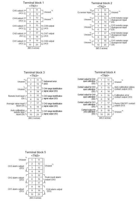
(7) List of terminal blocks 1 to 5
*1) Unused terminals are used for internal connection and should not be used as repeating terminals either.
*2) O2 sensor input is used when an external O2 analyzer is selected.
18 |
Model 7500 Instruction Manual |

 Teledyne Analytical Instruments
8) Description on terminal block
Terminal block 1 <TN1>
Terminal block for analog output (non-isolated output)
Output : 4 to 20 mA or 0 to 100V DC
Between 1 – |
2: |
CH5 output |
|
Between 3 |
– |
4: |
CH4 output |
Between 5 |
– |
6: |
CH3 output |
Between 7 |
– |
8: |
CH2 output |
Between 9 |
– 10: |
CH1 output |
|
Between 11 – 14: |
For internal connection. Must not be |
||
|
|
|
wired. (Must not be used as junction |
|
|
|
terminal.) |
Between 15 – 16: |
CH8 output |
||
Between 17– 18: |
CH7 output |
||
Between 19 – 20: |
CH6 output |
||
Terminal block 2 <TN2>
Between 1– 2: For O2 sensor input. (Input for our Zirconia oxygen sensor or external O2 sensor. Must not be used unless O2 meter is added.)
Between 3 –12: For internal connection. Must not be wired. (Must not be used as junction terminal.)
Between 13 – 14: CH4 remote range changeover input Between 15 – 16: CH3 remote range changeover input Between 17 – 18: CH2 remote range changeover input Between 19 – 20: CH1 remote range changeover input
Note: High range is selected when open. Low range is selected when short-circuited. For details of action, refer to “6.7 Parameters Setting, “Remote Range”.
19 |
Model 7500 Instruction Manual |

 Teledyne Analytical Instruments
Terminal block 3 <TN3>
Between 1 – 4: For internal connection. Must not be wired. (Must not be used as junction terminal.)
Between 5 – 6: Remote hold input. No hold when open.
Output hold when short-circuited.
Between 7 – 8: Average value reset input. Shortcircuiting the contact input (for at 1.5 sec or more) resets O2 average and O2 correction average simultaneously. Opening it restarts the average value.
Between 9 – 10: Automatic calibration remote start input. Open input after strapping for
at least 1.5 seconds starts the automatic calibration whether automatic calibration setting is ON or OFF.
Between 11 – 12: Conductive when analyzer unit error is producted. Normally open.
Between 13 – 14: CH4 range identification signal
Between 15 – 16: CH3 range identification signal
Between 17– 18: CH2 range identification signal
Between 19– 20: CH1 range identification signal
Note: Range identification signal is conductive at Low range or open at High range. In case of 1-range system, the signal remains open.
20 |
Model 7500 Instruction Manual |
 Teledyne Analytical Instruments
Terminal block 4 <TN4>
Between 1 – 2: CH4 span calibration contact output
Between 3 – 4: CH3 span calibration contact output
Between 5 – 6: CH2 span calibration contact output
Between 7 – 8: CH1 span calibration contact
Between 9 – 10: Zero calibration contact output When the calibration contact output is measured with manual calibration, the calibration contact corresponding to calibration channel is conductive.
For the automatic calibration, they are worked sequentially according to “6.4 Auto calibration setting”. If calibration is not performed, all of them are open.
Between 11 – 12: For internal connection. Must not be wired. (Must not be used as junction terminal.)
Between 13 – 14: Automatic calibration in progress, contact output.
Conductive during automatic calibration. Open otherwise.
Between 15 – 16: Calibration error contact output. Conductive when error is produced at zero or span calibration. Normally open.
Between 17 – 18: Pump ON/OFF contact output. (Used for turning ON/OFF the pump. Conductive during measurement and open at zero span calibration.)
21 |
Model 7500 Instruction Manual |
 Teledyne Analytical Instruments
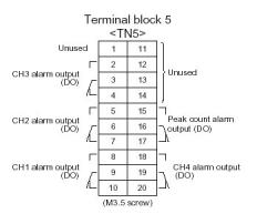
Terminal block 5 <TN5>
1 and 11 – 14: For internal connection. Must not be wired. (Must not be used as junction terminal.)
Between 2 - 3 and 3 - 4: CH3 alarm output. Conductive at 2 – 3 and open at 3 – 4 when set value is exceeded. Open at 2 – 3 and conductive at 3 – 4 otherwise.
Between 5 - 6 and 6 - 7: CH2 alarm output. Conductive at 5 – 6 and open at 6 – 7 when set value is exceeded. Open at 5 – 6 and conductive at 6 – 7 otherwise.
Between 8 - 9 and 9 - 10: CH1 alarm output. Conductive at 8 – 9 and open at 9 – 10 when set value is exceeded. Open at 8 – 9 and conductive at 9 – 10 otherwise.
Between 15 - 16 and 16 - 17: Peak count alarm contact output. Conductive at 15 – 16 and open at 16 – 17 when preset peak count is exceed. Otherwise, open at 15 – 16 and conductive at 16 – 17. For setting and action, refer to instruction manual “6.6 Peak Alarm Setting”.
Between 18 – 19 and 19 – 20: CH4 alarm output. Conductive at 18 – 19 and open at 19 – 20 when set value is exceeded. Open at 18 – 19 and conductive at 19 – 20 otherwise.
22 |
Model 7500 Instruction Manual |

 Teledyne Analytical Instruments
(9) Timing of calibration contact output
1. Manual calibration (See “6.9 Calibration”)
2. In case of automatic calibration (example shown in 6.4.1, Automatic calibration settings)
23 |
Model 7500 Instruction Manual |
 Teledyne Analytical Instruments
4. OPERATION
4.1 Preparation for operation
(1) Check of gas sampling tube, exhaust tube and wiring
Check that the pipes are correctly connected to the gas sampling port and drain port. Check that the analyzer is correctly wired as specified.
4.2 Warm-up operation and regular operation
(1) Operation procedure
1. Turn ON the power switch at the left of the front panel.
In one or two seconds, the measurement screen will appear at the front panel.
2. About 2 hour warm-up operation
About 2 hours are needed until the operating performance is stabilized. Warm-up operation should be continued with the power ON.
3. Setting of various set values
Set required set values according to Chapter 6, “Setting and calibration”.
4. Zero and span calibration
Perform zero calibration and span calibration after warm-up operation. See Chapter 6.9, “Calibration”.
5. Introduction and measurement of measured gas
Start measurement by introducing measured gas into the analyzer.
Note: While in warm-up operation, the concentration reading may be beyond the upper limit of the range (range-over) or below the lower limit. But this is not an error.
24 |
Model 7500 Instruction Manual |
 Loading...