


 Loading...
OPERATION MANUAL
Ultrafine Particle Monitor
MODEL 651
© Teledyne Advanced Pollution Instrument (TAPI)
9480 Carroll Park Drive
San Diego, CA 92121-5201
USA
Toll-free Phone: 800-324-5190
Phone: 858-657-9800
Fax: 858-657-9816
Email: api-sales@teledyne.com
Website: http://www.teledyne-api.com/
Copyright 2011-2013 |
07506C DCN6727 |
Teledyne Advanced Pollution Instrumentation |
17 June 2013 |

A b o u t T e l e d y n e I n s t r u m e n t a t i o n
A d v a n c e d P o l l u t i o n ( T A P I )
Teledyne Advanced Pollution Instrumentation (TAPI), a business unit of Teledyne Instruments, Inc., is a world leader in the design and manufacture of precision analytical instrumentation for trace gas analysis. Founded in San Diego, California, in 1988, TAPI introduced a complete line of Air Quality Monitoring (AQM) instrumentation, which complied with the Environmental Protection Administration (EPA) requirements for the measurement of criteria gases consisting of CO, SO2, NOX and Ozone.
Since that time, TAPI has introduced many features to these products and has grown to the position of the leading producer of AQM instrumentation, providing state of the art analytical products on a world wide basis. Our instruments comply with US EPA regulations as well as a number of other international requirements.
NOTICE OF COPYRIGHT
© 2011-2013 Teledyne Advanced Pollution Instrumentation. All rights reserved.
TRADEMARKS
All trademarks, registered trademarks, brand names or product names appearing in this document are the property of their respective owners and are used herein for identification purposes only.
07506C DCN6727 |
i |

This page intentionally left blank.
ii |
07506C DCN6727 |
S a f e t y M e s s a g e s
Important safety messages are provided throughout this manual for the purpose of avoiding personal injury or instrument damage. Please read these messages carefully. Each safety message is associated with a safety alert symbol, and are placed throughout this manual; the safety symbols are also located inside the instrument. It is imperative that you pay close attention to these messages, the descriptions of which are as follows:
WARNING: Electrical Shock Hazard
HAZARD: Strong oxidizer
GENERAL WARNING/CAUTION: Read the accompanying message for specific information.
CAUTION: Hot Surface Warning
Do Not Touch: Touching some parts of the instrument without protection or proper tools could result in damage to the part(s) and/or the instrument.
Technician Symbol: All operations marked with this symbol are to be performed by qualified maintenance personnel only.
Electrical Ground: This symbol inside the instrument marks the central safety grounding point for the instrument.
Laser radiation warning. Take appropriate cautionary measures to avoid exposure to radiation.
|
CAUTION |
|
|
|
This instrument should only be used for the purpose and in the manner described |
|
|
|
in this manual. If you use this instrument in a manner other than that for which it |
|
|
|
was intended, unpredictable behavior could ensue with possible hazardous |
|
|
|
consequences. |
|
|
|
NEVER use any gas analyzer to sample combustible gas(es)! |
|
|
Note |
For Technical Assistance regarding the use and maintenance of this |
||
instrument or any other Teledyne API product, please contact Teledyne API’s |
|||
|
|||
|
Technical Support Department: |
||
Telephone: 800-324-5190 Email: sda_techsupport@teledyne.com or access the service options on our website: http://www.teledyne-api.com/.
07506C DCN6727 |
iii |

Laser Safety
The Ultrafine Particle Monitor – Model 651 is a Class I laser-based instrument. During normal operation, you will not be exposed to laser radiation. To avoid exposing yourself at any time to hazardous radiation in the form of intense, focused visible light (exposure to this light can cause blindness), take these precautions:
Do not remove any parts from the instrument unless you are specifically told to do so in this manual.
Do not remove the instrument housing or cover while power is supplied to the instrument.
W A R N I N G
The use of controls, adjustments, or procedures other than those specified in this manual may result in exposure to hazardous optical radiation, which can cause blindness.
iv |
07506C DCN6727 |
W a r r a n t y
WARRANTY POLICY (02024F)
Teledyne Advanced Pollution Instrumentation (TAPI), a business unit of Teledyne Instruments, Inc., provides that:
Prior to shipment, TAPI equipment is thoroughly inspected and tested. Should equipment failure occur, TAPI assures its customers that prompt service and support will be available.
COVERAGE
After the warranty period and throughout the equipment lifetime, TAPI stands ready to provide on-site or in-plant service at reasonable rates similar to those of other manufacturers in the industry. All maintenance and the first level of field troubleshooting are to be performed by the customer.
NON-TAPI MANUFACTURED EQUIPMENT
Equipment provided but not manufactured by TAPI is warranted and will be repaired to the extent and according to the current terms and conditions of the respective equipment manufacturer’s warranty.
PRODUCT RETURN
All units or components returned to Teledyne API should be properly packed for handling and returned freight prepaid to the nearest designated Service Center. After the repair, the equipment will be returned, freight prepaid.
The complete Terms and Conditions of Sale can be reviewed at http://www.teledyne-api.com/terms_and_conditions.asp
CAUTION – Avoid Warranty Invalidation
Failure to comply with proper anti-Electro-Static Discharge (ESD) handling and packing instructions and Return Merchandise Authorization (RMA) procedures when returning parts for repair or calibration may void your warranty. For antiESD handling and packing instructions please refer to “Packing Components for Return to Teledyne API’s Customer Service” in the Primer on Electro-Static Discharge section of this manual, and for RMA procedures please refer to our Website at http://www.teledyne-api.com under Customer Support > Return Authorization.
07506C DCN6727 |
v |

This page intentionally left blank.
vi |
07506C DCN6727 |

A b o u t T h i s M a n u a l
This Model 651 manual, PN 07506, is accompanied by a Quick Guide document, PN 07507, which provides critical information that is critical to the proper and safe initial setup and timely maintenance, and proper handling of this instrument.
CAUTION – AVOID WARRANTY INVALIDATION
Failure to comply with proper setup, maintenance and handling of this instrument will void the warranty. Please read both the Quick Guide and this Operation Manual before proceeding with operation of this instrument.
R e v i s i o n H i s t o r y
2013, June, Model 651 Manual, 07506C, DCN 6727, updates to reflect hardware changes
2012, March, Model 651 Manual, 07506B, DCN 6400, administrative corrections and specs corrections: Inlet pressure, power requirements – max W)
2012, March, Model 651 Quick-guide (separate document), 07507B, DCN 6401, administrative correction.
2011, August, Model 651 Manual, PN 07506 Rev A, DCN 6190, Initial Release
2011, August, Model 651 Quick-Guide (separate document), PN 07507 Rev A, DCN 6190, Initial Release
07506C DCN6727 |
vii |

This page intentionally left blank.
viii |
07506C DCN6727 |
Contents
OPERATION MANUAL ....................................................................................... |
i |
About Teledyne Advanced Pollution Instrumentation (TAPI) ................. |
i |
Safety Messages .................................................................................. |
iii |
Laser Safety....................................................................................... |
iv |
Warranty................................................................................................. |
v |
About This Manual ............................................................................... |
vii |
Revision History ................................................................................... |
vii |
Contents................................................................................................................. |
ix |
Figures ................................................................................................. |
xii |
Tables .................................................................................................. |
xiii |
How This Manual is Organized.......................................................................... |
xv |
Purpose................................................................................................ |
xv |
Organization......................................................................................... |
xv |
Related Product Literature.................................................................. |
xvi |
Getting Help ........................................................................................ |
xvi |
CHAPTER 1......................................................................................................... |
17 |
Product Overview................................................................................................ |
17 |
Product Description.............................................................................. |
17 |
Specifications....................................................................................... |
18 |
How it Works........................................................................................ |
20 |
CHAPTER 2......................................................................................................... |
23 |
Unpacking and Setting Up the Model 651 ......................................................... |
23 |
Packing List.......................................................................................... |
23 |
Unpacking ............................................................................................ |
24 |
Installation............................................................................................ |
25 |
Equipment......................................................................................... |
25 |
Remove Protective Caps.................................................................. |
25 |
Connecting the Water Supply........................................................... |
25 |
Connecting the Water Exhaust Tube................................................ |
27 |
Connecting the Aerosol Supply ........................................................ |
27 |
Installing the Model 651 in a Rack.................................................... |
30 |
Connecting the USB Cable............................................................... |
31 |
Connecting Power and Warming up the Model 651......................... |
31 |
CHAPTER 3......................................................................................................... |
33 |
Moving and Shipping the Model 651 ................................................................. |
33 |
Moving the Model 651 Short Distances............................................ |
33 |
Preparing the Model 651 for Shipping and Storage ......................... |
33 |
CHAPTER 4......................................................................................................... |
35 |
Instrument Description ....................................................................................... |
35 |
07506C DCN6727 |
ix |

Contents |
Teledyne API Ultrafine Particle Monitor - Model 651 |
|
|
Front Panel .......................................................................................... |
35 |
|
Display.............................................................................................. |
35 |
|
Status Messages.............................................................................. |
36 |
|
Indicator Light................................................................................... |
36 |
|
Back Panel........................................................................................... |
37 |
|
Internal Instrument Components ......................................................... |
38 |
|
Optics Module................................................................................... |
38 |
|
Vacuum Supply ................................................................................ |
38 |
|
Water System................................................................................... |
39 |
|
Fans.................................................................................................. |
39 |
|
Circuit Boards ................................................................................... |
39 |
|
Internal Clock.................................................................................... |
39 |
|
Data Communication Ports .............................................................. |
40 |
|
CHAPTER 5......................................................................................................... |
43 |
|
Instrument Operation.......................................................................................... |
43 |
|
Operating Precautions......................................................................... |
43 |
|
Recommended Operation Procedures................................................ |
43 |
|
Outdoor Operation Procedures ........................................................ |
43 |
|
Standard Operation Procedures....................................................... |
44 |
|
Warm-up .............................................................................................. |
45 |
|
Display/User Settings .......................................................................... |
45 |
|
HOME Screen .................................................................................. |
45 |
|
STATUS Screens ............................................................................. |
45 |
|
SETUP Screens ............................................................................... |
47 |
|
TOTAL Screen.................................................................................. |
51 |
|
CHAPTER 6......................................................................................................... |
53 |
|
Technical Description .......................................................................................... |
53 |
|
Theory.................................................................................................. |
53 |
|
Design of the Model 651...................................................................... |
54 |
|
Sensor .............................................................................................. |
54 |
|
Flow System..................................................................................... |
56 |
|
Critical Flow ...................................................................................... |
56 |
|
Temperature Control ........................................................................ |
57 |
|
Vacuum Supply ................................................................................ |
57 |
|
Inlet Pressure Measurement ............................................................ |
57 |
|
Water Removal System.................................................................... |
58 |
|
Counting Efficiency and Response Time of the Model 651................. |
58 |
|
CHAPTER 7......................................................................................................... |
61 |
|
Particle Counting ................................................................................................. |
61 |
|
Total Count Accuracy .......................................................................... |
61 |
|
Live-Time Counting.............................................................................. |
62 |
|
Concentration Measurement ............................................................... |
63 |
|
Totalizer Mode ..................................................................................... |
65 |
|
CHAPTER 8......................................................................................................... |
67 |
|
Computer Interface, Commands, and Data Collection .................................... |
67 |
|
Computer Interface.............................................................................. |
67 |
x |
07506C DCN6727 |

Teledyne API Ultrafine Particle Monitor - Model 651 |
Contents |
|
Ethernet ............................................................................................ |
|
67 |
Flash Drives...................................................................................... |
|
69 |
USB................................................................................................... |
|
72 |
RS-232 Serial Communications ....................................................... |
|
72 |
Terminal Communications................................................................ |
|
73 |
Commands........................................................................................... |
|
74 |
CHAPTER 9......................................................................................................... |
|
77 |
Maintenance, Service, and Troubleshooting ..................................................... |
|
77 |
Removing the Cover ............................................................................ |
|
78 |
Replacement Parts Kits ....................................................................... |
|
78 |
Removing and Installing the Wick........................................................ |
|
79 |
Changing the Filters............................................................................. |
|
81 |
Aerosol Flow Checks ........................................................................... |
|
82 |
Cleaning the Water Bottle.................................................................... |
|
84 |
Inspecting and Cleaning the Fans ....................................................... |
|
85 |
Clean/Replace the Orifices .................................................................. |
|
85 |
Inspect Liquid Lines ............................................................................. |
|
86 |
Status Messages ................................................................................. |
|
87 |
Troubleshooting ................................................................................... |
|
88 |
Technical Assistance ........................................................................... |
|
90 |
Returning the Model 651 for Service ................................................... |
|
90 |
Chapter 10............................................................................................................ |
|
91 |
Primer on Electro-Static Discharge ................................................................... |
|
91 |
How Static Charges Are Created......................................................... |
|
91 |
How Electro-Static Charges Cause Damage....................................... |
|
92 |
Common Myths About ESD Damage .................................................. |
|
94 |
Basic Principles of Static Control......................................................... |
|
95 |
General Rules................................................................................... |
|
95 |
Basic Anti-ESD Procedures for Instrument Repair and Maintenance .97 |
||
Working at the Instrument Rack ....................................................... |
|
97 |
Working at an Anti-ESD Work Bench............................................... |
|
97 |
Transferring Components from Rack to Bench and Back ................ |
|
98 |
Opening Shipments from Teledyne API’S Customer Service |
.......... |
98 |
Packing Components for Return to TAPI’s Customer Service......... |
99 |
|
APPENDIX A Firmware Commands ................................................................... |
|
1 |
READ Commands.................................................................................. |
|
3 |
RAI – Read Analog Input Voltage....................................................... |
|
3 |
RALL – Read Operating Condition..................................................... |
|
4 |
RCT – Read Current Time.................................................................. |
|
5 |
RD – Read Displayed Concentration.................................................. |
|
5 |
RIE – Read Instrument Errors ............................................................ |
|
6 |
RIF – Read Aerosol Flow Rate........................................................... |
|
6 |
RIS – Read Instrument Status............................................................ |
|
7 |
RL – Read Laser Current.................................................................... |
|
7 |
RLL – Read Liquid Level .................................................................... |
|
8 |
RPA – Read Absolute Pressure Transducer...................................... |
|
8 |
RPN – Read Nozzle Pressure Transducer......................................... |
|
8 |
07506C DCN6727 |
xi |

Contents |
Teledyne API Ultrafine Particle Monitor - Model 651 |
|
|
RPV – Read Vacuum Pressure.......................................................... |
8 |
|
RRD – Read Data Record.................................................................. |
9 |
|
RRS – Read Status Record ............................................................. |
10 |
|
RTA – Read Cabinet Temperature................................................... |
10 |
|
RTC – Read Conditioner Temperature ............................................ |
10 |
|
RTG – Read Growth Tube Temperature.......................................... |
11 |
|
RTO – Read Optics Temperature .................................................... |
11 |
|
RV – Read Firmware Version Number............................................. |
11 |
|
SET Commands .................................................................................. |
12 |
|
SM – Set Mode................................................................................. |
12 |
|
SA – Set Auxiliary Flow Valve .......................................................... |
13 |
|
SFC – Set Flow Rate Calibration Constant...................................... |
13 |
|
SP – Set Pump Vacuum................................................................... |
14 |
|
SR – Set Real-time Clock................................................................. |
14 |
|
SSTART – Starts a New Sample ..................................................... |
15 |
|
ST – Set Transport Flow................................................................... |
16 |
|
DATA Reporting Records .................................................................... |
16 |
|
D Record .......................................................................................... |
17 |
|
S Record (Status)............................................................................. |
18 |
|
Index............................................................................................................. |
Index-1 |
F i g u r e s |
|
FIGURE 1-1 ULTRAFINE PARTICLE MONITOR - MODEL 651 ........................................................................ |
18 |
FIGURE 1-2 MODEL 651 FLOW SYSTEM SCHEMATIC................................................................................... |
22 |
FIGURE 2-1 CONNECTING THE WATER SUPPLY ........................................................................................... |
26 |
FIGURE 2-2 WATER FILL AND WATER EXHAUST FITTINGS.......................................................................... |
27 |
FIGURE 2-3 CONNECTING THE AEROSOL SUPPLY....................................................................................... |
28 |
FIGURE 2-4 CONNECTING THE AEROSOL SUPPLY TO INLET SCREEN ASSEMBLY................................. |
29 |
FIGURE 2-5 SECURING INLET SCREEN ASSEMBLY IN PLACE..................................................................... |
29 |
FIGURE 2-6 CONNECTING EXTERNAL VACUUM SOURCE............................................................................ |
30 |
FIGURE 2-7 INSTALLING MODEL 651 IN A RACK ............................................................................................ |
31 |
FIGURE 2-8 WARM-UP SCREEN........................................................................................................................ |
32 |
FIGURE 4-1 MODEL 651 FRONT PANEL........................................................................................................... |
35 |
FIGURE 4-2 MODEL 651 BACK PANEL.............................................................................................................. |
37 |
FIGURE 4-3 MODEL 651 INTERNAL COMPONENTS (VIEWED FROM INSTRUMENT FRONT).................... |
38 |
FIGURE 6-1 COUNTING EFFICIENCY CURVE OF MODEL 651....................................................................... |
59 |
FIGURE 6-2 RESPONSE TIME OF MODEL 651................................................................................................. |
59 |
FIGURE 8-1 SCREEN SHOWING VALID NETWORK CONNECTION ............................................................... |
69 |
FIGURE 9-1 LOADING NEW WICK INTO SPARE WICK CARTRIDGE ............................................................. |
79 |
FIGURE 9-2 REMOVING INLET SCREEN ASSEMBLY...................................................................................... |
79 |
FIGURE 9-3 NOZZLE JACK SCREW .................................................................................................................. |
80 |
FIGURE 9-4 REMOVING WICK ........................................................................................................................... |
80 |
FIGURE 9-5 LOCATION OF FILTERS................................................................................................................. |
81 |
FIGURE 9-6 CHANGING FILTER ........................................................................................................................ |
82 |
FIGURE 9-7 MODEL 651 FLOW SCHEMATIC................................................................................................... |
83 |
xii |
07506C DCN6727 |

Teledyne API Ultrafine Particle Monitor - Model 651 |
Contents |
FIGURE 9-8 EXTERNAL FLOW METER ATTACHED TO MODEL 651 |
..............................................................84 |
FIGURE 9-9 CLEANING/REPLACING ORIFICES............................................................................................... |
85 |
FIGURE 10-1 TRIBOELECTRIC CHARGING ...................................................................................................... |
91 |
FIGURE 10-2 BASIC ANTI-ESD WORK STATION.............................................................................................. |
95 |
T a b l e s |
|
|
TABLE 1-1 MODEL 651 SPECIFICATIONS................................................................................................... |
18 |
|
TABLE 2-1 |
MODEL 651 PACKING LIST ......................................................................................................... |
23 |
TABLE 2-2 |
MODEL 651 MAINTENANCE KIT PN DU0000169....................................................................... |
24 |
TABLE 9-1 |
MODEL 651 MAINTENANCE AND REPLACEMENT KITS.......................................................... |
78 |
TABLE 9-2 |
TROUBLESHOOTING ............................................................................................................. |
88 |
TABLE 10-1 |
STATIC GENERATION VOLTAGES FOR TYPICAL ACTIVITIES ............................................... |
92 |
TABLE10-2 |
SENSITIVITY OF ELECTRONIC DEVICES TO DAMAGE BY ESD ............................................ |
93 |
TABLE A-1 |
MODEL 651 FIRMWARE COMMANDS...................................................................................... |
A-2 |
07506C DCN6727 |
xiii |

Contents |
Teledyne API Ultrafine Particle Monitor - Model 651 |
This page intentionally left blank.
xiv |
07506C DCN6727 |

How This Manual is
Organized
P u r p o s e
This is an operation and service manual for the Ultrafine Particle
Monitor - Model 651.
O r g a n i z a t i o n
The following information is a guide to the organization of this manual.
Chapter 1: Product Overview
Contains an introduction to the Model 651, a list of features, the specifications, and a brief description of how the instrument works.
Chapter 2: Unpacking and Setting Up the Model 651
Contains a packing list and the step-by-step procedures for installing the Model 651.
Chapter 3: Moving and Shipping the Model 651
Describes how to prepare the Model 651 for moving and shipping.
Chapter 4: Instrument Description
Describes features and controls that run the Model 651, including the components on the front-panel, back-panel, and inside the instrument. It also covers the basic functions of the instrument.
Chapter 5: Instrument Operation
Describes the operation of the Model 651.
Chapter 6: Technical Description
Describes the principle of operation, theory, and performance of the Model 651.
Chapter 7: Particle Counting
Contains information about the particle counting modes.
Chapter 8: Computer Interface, Commands, and Data Collection
Describes the computer interface, commands and data collection.
07506C DCN6727 |
xv |

How This Manual is Organized |
Teledyne API Ultrafine Particle Monitor - Model 651 |
Chapter 9: Maintenance, Service, and Troubleshooting
Describes the recommended practices for routine maintenance and service, as well as important troubleshooting procedures.
Chapter 10: Primer on Electro-Static Discharge
Describes how static electricity occurs and why it is so dangerous to electronic components and assemblies, as well as how to prevent that damage from occurring so that the instrument warranty is not invalidated.
Appendix A: Firmware Commands
Lists the main serial commands for communications between the Model 651 and the computer.
R e l a t e d P r o d u c t L i t e r a t u r e
TAPI Model 651 Quick Guide (part number 07507)
This single-sheet quick guide provides critical information about initial setup, operation, shipping, and maintenance of the instrument.
G e t t i n g H e l p
To obtain assistance with the M651, contact TAPI Technical
Support:
Toll-free Phone: 800-324-5190
Phone: 858-657-9800
Fax: 858-657-9816
Email: sda_techsupport@teledyne.com
Website: http://www.teledyne-api.com/
xvi |
07506C DCN6727 |

C H A P T E R 1
Product Overview
This chapter contains an introduction to the Ultrafine Particle Monitor - Model 651 and provides a brief explanation of how the instrument operates.
P r o d u c t D e s c r i p t i o n
The Model 651 is a continuous laminar flow condensation particle counter that uses water as its working fluid. The Model 651 provides rapid, high-precision measurement of the numbers of ultrafine (down to 7 nm) airborne particles. The instrument delivers robust field performance in both pristine and heavily polluted areas and can be used for a variety of applications including ambient monitoring and research, indoor air quality investigations, atmospheric and climate research, and health effects studies. TAPI recommends annual maintenance and calibration for the Model 651.
Features of the Model 651 include:
6-inch color touch screen with a graphical interface displaying particle concentration, total counts, and a plot of concentration vs. time.
7-nm detection.
Single-particle counting to 106 particles/cm3.
Continuous, live-time, electronic processing for maximum accuracy.
Adjustable inlet flow (3.0 or 0.6 L/min), inlet location (front or back), and water supply connection (front or back).
Flexible data acquisition options including USB stick, Ethernet, USB port, and RS-232 port.
Advanced instrument diagnostics including a novel pulse height analyzer to monitor super-saturation state, wick health, and instrument status.
Newly designed air flow, wicking, and water handling systems.
Option to mount in a rack with included hardware.
07506C DCN6727 |
17 |
Product Overview |
Teledyne API Ultrafine Particle Monitor - Model 651 |
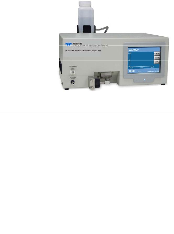
Figure 1-1
Ultrafine Particle Monitor - Model 651
S p e c i f i c a t i o n s
Table 1-1 contains the operating specifications for the Model 651 instrument. These specifications are subject to change without notice.
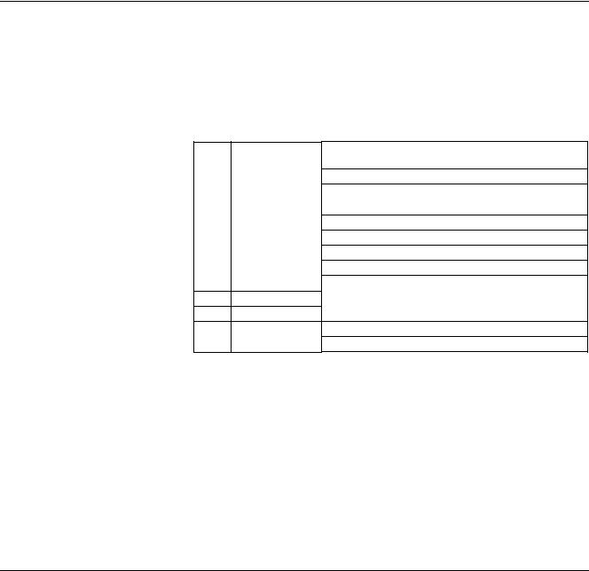
Table 1-1 Model 651 Specifications
PARAMETER |
|
SPECIFICATION |
Particle Size Range |
|
|
Min detectable particle (D50) |
|
7 nm (verified with DMA-classified sucrose) |
Max detectable particle |
|
3 μm |
Particle Concentration Range |
|
|
Single Particle Counting |
|
0 to 106 particles/cm3, with continuous live-time |
|
|
coincidence correction |
Particle Concentration Accuracy |
|
|
Measurement Accuracy |
|
±10% at 106 particles/cm3 |
Response Time (T95) |
|
|
High flow mode(3 L/min) |
|
<3 sec to 95% in response to concentration step |
|
|
change |
Low flow mode (0.6 L/min) |
|
<5 sec to 95% in response to concentration step |
|
|
change |
Flow |
|
|
High-flow inlet |
|
3 ±0.3 L/min |
Low-flow inlet |
|
0.6 ± 0.06 L/min |
18 |
07506C DCN6727 |
Teledyne API Ultrafine Particle Monitor - Model 651 |
Product Overview |
|
|
|
SPECIFICATION |
|
PARAMETER |
|
|
Aerosol flow rate |
120 ±12 cm3/min |
|
False Background Counts |
<0.01 particles/ cm3, one hour average |
|
False background counts |
|
|
Aerosol Medium |
|
|
Aerosol medium |
Air only |
|
Environmental Operating Conditions |
|
Ambient temp range
Ambient humidity range
Inlet Pressure Operation
10 to 38°C (50 to 100.4°F)
0 to 90% non-condensing
Inlet pressure operation |
50 to 110 KPa (0.5 to 1.1 atm) |
(absolute) |
|
Inlet pressure gauge |
1 to -5 kPa (-20 inch H20) |
Water System |
|
Condensing liquid |
Distilled water |
Water system |
External 1 liter bottle for up to 4 weeks of |
|
operation. |
Water consumption |
~250 ml/week |
Vacuum |
|
Vacuum |
External vacuum pump not included in |
|
instrument accessories |
Communications |
|
Protocol
Interfaces
RS-232
USB
Ethernet
Data Logging
Data logging
Averaging interval
Outputs
ASCII command set
9-pin, D-Sub connector
Type B connector, USB 2.0 compatible at 12 MB
8-wire RJ-45 jack, 10/100 BASE-T, TCP/IP
USB Flash drive
Data averaging interval of 1-3600s 1,2,4,5,6,10,12,15,20,30 or 60s software provides more avg options.
Digital display
Analog output
Digital output
Calibration
Calibration
Power
Requirements
9-inch QVGA color touch screen with graphical interface. Graph of conc vs. time, concentration, time and total counts, and status
BNC connector, 0 to 10V proportional to concentration, or 0 to 7V in LOG concentration mode.
Data download using USB, RS-232 serial, or Ethernet interface
Recommended annually
100 to 240 VAC, 50/60 HZ, 175 W max
07506C DCN6727 |
19 |

Product Overview |
Teledyne API Ultrafine Particle Monitor - Model 651 |
|
||
|
|
|
|
|
|
PARAMETER |
|
SPECIFICATION |
|
|
Physical Features |
|
|
|
|
Front panel |
|
Display, sample inlet, LED particle indicator |
|
|
Back panel |
|
Power connector, USB, Ethernet, RS-232, BNC |
|
|
|
|
output, fan, water fill connector, pump exhaust |
|
|
|
|
port, fill bottle and bracket |
|
|
HxDxW |
|
20.3 x 48.3 x 30.5 cm (8 x 19 x 12 inches) |
|
|
Weight |
|
9.9 Kg (22 lbs) |
|
H o w i t W o r k s
The Ultrafine Particle Monitor - Model 651 is designed to measure the concentration of airborne particles. The Model 651 draws in an air sample and counts the number of particles in that sample to provide a particle concentration value that is displayed as the number of particles detected per cubic centimeter of sampled air.
The Model 651 utilizes a patented* laminar-flow, water-based condensation growth technique. Particles which are too small (nanometer scale) to scatter enough light to be detected by conventional optics are grown to a larger size by condensing water on them. In this instrument, an air sample is continuously drawn through the inlet via an external pump and a portion of the flow is sent to the exhaust as transport flow. The stream of aerosol particles is uninterrupted and follows a laminar flow path from the sample inlet to the optical detector.
The Model 651 particle counting process is as follows:
The aerosol enters the sample inlet.
In the conditioner, the aerosol sample stream is saturated with water vapor and then temperature-equilibrated.
The sample passes to a growth tube where the wetted walls (composed of a porous medium) are heated to raise the vapor pressure. The high diffusivity of the water vapor allows the vapor to reach the center of the sample stream at a faster rate than the thermal diffusivity of the vapor can equilibrate to the higher temperatures near the walls—creating a supersaturated condition along the radius of the flow stream. These unstable conditions facilitate water condensation on the sample particles.
Particles that are larger than the detection limit of the Model 651’s minimum critical particle size act as condensation nuclei as they pass up the growth tube.
*US Patent No. 6,712,881, Aerosol Dynamics Inc., Drs. Susanne V. Hering and Mark Stolzenburg.
20 |
07506C DCN6727 |

Teledyne API Ultrafine Particle Monitor - Model 651 |
Product Overview |
The enlarged particles are passed through a laser beam and create a large light pulse. Every particle pulse event is detected and counted. In this technique, particle concentration is measured by counting each particle in the air stream.
Figure 1-2 illustrates the flow system of the Model 651.
07506C DCN6727 |
21 |

Product Overview |
Teledyne API Ultrafine Particle Monitor - Model 651 |
Figure 1-2
Model 651 Flow System Schematic
22 |
07506C DCN6727 |
C H A P T E R 2
Unpacking and Setting
Up the Model 651
Use the information in this chapter to unpack and set up the
Ultrafine Particle Monitor - Model 651.
P a c k i n g L i s t
The packing list described in Table 2-1 shows the components shipped with the Model 651.
Table 2-2 shows the components included in the Model 651
Maintenance Kit.
Table 2-1 Model 651 Packing List
|
Part Number/ |
|
Qty. |
Model Number |
Description |
1 |
081000000 |
Ultrafine Particle Monitor - Model 651 |
1 |
076220000 |
TAPI Manuals on CD-ROM(KB) |
1 |
075070000 |
Model 651 Quick Start Guide |
1 |
WR0000008 |
Power cable, 10A |
1 |
DU0000167 |
Water supply bottle |
1 |
DU0000168 |
Water drain bottle |
1 |
DU0000177 |
Vacuum pump tubing |
1 |
WR0000257 |
Cable, USB, com |
1WR0000101 RS-232 Serial cable, DB9 M/F DU0000175 Vacuum pump, 115V, 60Hz
1 |
DU0000169 |
Maintenance Kit (for details see Table 2-2 below) |
1 |
KIT000400 |
Inlet Mounting Kit |
Note: Some items above and those for future maintenance are available for purchase as kits from TAPI. A complete list of replacement parts is included in the Maintenance section in Chapter 9.
07506C DCN6727 |
23 |
Unpacking and Setting Up the Model 651 |
|
Teledyne API Ultrafine Particle Monitor - Model 651 |
||
|
Table 2-2 Model 651 Maintenance Kit PN DU0000169 |
|||
|
Qty. |
Part Number |
Description |
|
|
1 |
DU0000150 |
Static Dissipative Sample Inlet Tubing (3M) |
|
|
3 |
DU0000234 |
Filter Replacements M651 |
|
|
1 |
DU0000161 |
Replacement Critical Flow Control Orifice .005 inch |
|
|
1 |
DU0000162 |
Replacement Critical Transport Flow Control Orifice |
|
|
|
|
.0095 inch |
|
|
1 |
DU0000163 |
Replacement Critical Auxiliary Flow Control Orifice |
|
|
|
|
.0225 inch |
|
|
1 |
DU0000157 |
3783 Wick Cartridge |
|
|
12 |
DU0000158 |
Wick 3783: Replacement Wicks |
|
|
1 |
DU0000178 |
Three-foot length of 1/8 inch tubing |
|
U n p a c k i n g
Carefully unpack the Model 651 from the shipping container (refer to Chapter 10 to avoid damage due to Electro-Static Discharge). Check to ensure there is no damage to the instrument. If any damage is found, contact the carrier. Use the Packing List in Table 2-1 to verify that there are no missing components.
Save the original shipping container to be used for future shipping.
If anything is missing, TAPI Technical Support by phone or by email:
Phone: |
1-800-324-5190 (within the US) |
|
001-858-657-9800 (outside the US) |
|
858-657-9800 (local) |
E-mail: |
sda_techsupport@teledyne.com. |
See Chapter 9 for instructions on how to return the instrument to TAPI, and Chapter 3 for moving/shipping procedures.
Caution – Prevent Damage and Avoid Warranty Invalidation
The Ultrafine Particle Monitor - Model 651 operates using distilled (<6 ppm) or HPLC water as a working fluid. Do not tip the instrument
more than 10 degrees during normal operation. Perform the procedures described in Chapter 3 before moving or shipping the instrument.
Do not:
Ship an “undried” instrument.
Transport an “undried” instrument over long distances.
Subject an “undried” instrument to freezing temperatures.
Any of the above actions can result in the flooding of the optical system, performance degradation, and possible damage to the instrument. Such neglect is not covered under the manufacturer’s warranty.
24 |
07506C DCN6727 |

Teledyne API Ultrafine Particle Monitor - Model 651 |
Unpacking and Setting Up the Model 651 |
I n s t a l l a t i o n
I M P O R T A N T
The wick used in the M651 must be changed every 4 weeks (800 hours), and distilled (<6 ppm) or HPLC water must be used as the water source. Follow the instructions in Chapter 9 for wick replacement.
This section contains instructions for installing the Model 651 instrument. Follow the instructions in the order given.
The installation procedures, described on the following pages, include the following:
Removing protective caps.
Connecting the water supply.
Connecting the water exhaust tube.
Connecting the aerosol supply and vacuum line.
Installing the Model 651 in a rack (if desired).
Connecting the USB cable.
Connecting the power and warming up the Model 651.
Equipment
You will need the following equipment to install the Model 651:
9/16 inch wrench.
7/64 inch hex driver.
¼-inch, thick-walled, plastic tubing.
Water supply.
Note: Use either distilled (<6 ppm) or HPLC water. Do not use tap water.
Remove Protective Caps
After unpacking the Model 651, remove the protective caps from the AEROSOL INLETs on the front and back panels of the instrument and from the PUMP EXHAUST. Then remove the covers from the BNC connectors.
Connecting the Water Supply
The Model 651 uses a gravity-fed water fill system.
Note: To prevent the water from draining back into the bottle during operation, the bottle must always be placed at a higher level than the instrument.
07506C DCN6727 |
25 |
Unpacking and Setting Up the Model 651 |
Teledyne API Ultrafine Particle Monitor - Model 651 |
To connect the water supply, follow these instructions:
1.Using a 7/64 inch hex driver, mount the water supply bottle bracket to the front or back of the particle counter using the provided bottle bracket mounting screws. The figure below shows the bracket mounted on the back.
Bracket
Screw
Figure 2-1
Connecting the Water Supply
2.Fill the water supply bottle with either distilled (<6 ppm) or HPLC water and place the bottle in the bracket.
Note: A filled water supply bottle will typically allow the Model 651 to operate for more than the 4-weeks wick replacement interval. If water is added between the wick change, it is recommended that the water be added to the bottle without disconnecting it from the Model 651 to avoid adding any bubbles into the water supply line.
3.Push the connector on the water supply bottle tubing into the WATER FILL fitting on either the front or back of the instrument (figure below shows the back).
26 |
07506C DCN6727 |
Teledyne API Ultrafine Particle Monitor - Model 651 |
Unpacking and Setting Up the Model 651 |
WATER FILL
Fitting
WATER EXHAUST
Fitting
Figure 2-2
Water Fill and Water Exhaust Fittings
Connecting the Water Exhaust Tube
The waste water should pass into a suitable drain such as a floor drain or a vented container. To connect the drain tube:
1.Push the connector on the supplied length of drain tubing into the WATER EXHAUST fitting on the back panel.
2.Place the other end of the drain tube in a vented container or over a floor drain.
Connecting the Aerosol Supply
The Model 651 allows you to conduct aerosol sampling from either the front or the back of the instrument. To run the instrument effectively, you need an external vacuum capable of drawing
6 SLPM at 400 mbar absolute pressure. Sampling options include the following:
Ambient sampling using the inlet screen assembly (provided with the monitor) connected to the Model 651 inlet. The inlet screen assembly prevents large matter (such as insects and dirt) from entering the instrument.
Note: If you are sampling from the back of the instrument, you must use the inlet screen assembly and the flow rate must be 3 L/min when using the inlet screen.
07506C DCN6727 |
27 |
Unpacking and Setting Up the Model 651 |
Teledyne API Ultrafine Particle Monitor - Model 651 |
Using a sampling system connected directly to the aerosol inlet.
Environmental monitoring using tubing connected directly to the aerosol inlet.
I M P O R T A N T
The gauge pressure of the sampled aerosol must be within +4/-20 in. H2O pressure relative to the ambient pressure. Pressures outside of this range will result in water-handling failures.
To set up the aerosol supply, follow these instructions:
1.Decide whether you will sample from the front or the back of the instrument.
2.Place the aerosol sample inlet cap over the sample port that you will not be using.
3.Determine your sampling method. The instrument is shipped with the inlet screen assembly in place, but if it has been removed and you wish to use it, you must reconnect it to the Model 651 inlet. If you are not using the inlet screen, connect the aerosol sample line to the aerosol inlet.
Figure 2-3
Connecting the Aerosol Supply
4.If you are using the inlet screen assembly and it needs to be connected, line up the two captive screws with the corresponding holes on the front panel. The elbow tube should line up with the nozzle.
28 |
07506C DCN6727 |
Loading...