


 Loading...
TECHNICAL MANUAL
MODEL 400E
PHOTOMETRIC OZONE ANALYZER
© TELEDYNE INSTRUMENTS
ADVANCED POLLUTION INSTRUMENTATION DIVISION (TAPI)
9480 CARROLL PARK DRIVE
SAN DIEGO, CALIFORNIA 92121-5201
USA
Toll-free Phone: |
800-324-5190 |
Phone: |
858-657-9800 |
Fax: |
858-657-9816 |
Email: |
api-sales@teledyne.com |
Website: |
http://www.teledyne-api.com/ |
Copyright 2007 |
|
Teledyne Advanced Pollution Instrumentation |
04316 Rev. E |
|
DCN 5473 |
|
16 June 2009 |
THIS PAGE IS INTENTIONALLY LEFT BLANK

M400E Ozone Analyzer Operator’s Manual |
Table of Contents |
|
TABLE OF CONTENTS |
|
|
GENERAL INFORMATION .................................................................................. |
|
1 |
1. INTRODUCTION .................................................................................................................. |
|
3 |
1.1. Safety Messages............................................................................................................................................ |
|
3 |
1.2. M400E Overview............................................................................................................................................ |
|
4 |
1.3. Using This Manual ......................................................................................................................................... |
|
5 |
2. SPECIFICATIONS, APPROVALS AND WARRANTY ......................................................... |
7 |
|
2.1. Specifications................................................................................................................................................. |
|
7 |
2.2. EPA Equivalency Designation ....................................................................................................................... |
|
9 |
2.3. CE Mark Compliance ..................................................................................................................................... |
|
9 |
2.4. Warranty....................................................................................................................................................... |
|
10 |
3. GETTING STARTED .......................................................................................................... |
|
11 |
3.1. Model 400E Analyzer Layout ....................................................................................................................... |
|
11 |
3.2. Unpacking the M400E analyzer................................................................................................................... |
|
15 |
3.2.1.1. Ventilation Clearance ..................................................................................................................... |
|
16 |
3.3. Electrical Connections ................................................................................................................................. |
|
16 |
3.3.1. Power Connection.................................................................................................................................. |
|
16 |
3.3.2. Analog Output Connections................................................................................................................... |
|
17 |
3.3.3. Connecting the Status Outputs.............................................................................................................. |
|
18 |
3.3.4. Connecting the Control Inputs ............................................................................................................... |
|
19 |
3.3.5. Connecting the Serial Ports ................................................................................................................... |
|
20 |
3.3.6. Connecting to a LAN or the Internet ...................................................................................................... |
|
20 |
3.3.7. Connecting to a Multidrop Network........................................................................................................ |
|
20 |
3.4. Pnenumatic Connections ............................................................................................................................. |
|
21 |
3.4.1. About Zero Air and Calibration Gas....................................................................................................... |
|
21 |
3.4.2. Basic Pneumatic Setup for the M400E analyzer ................................................................................... |
22 |
|
3.4.3. Pneumatic Setup for the M400E Analyzer with Internal Zero/Span Option (IZS) ................................. |
23 |
|
3.4.4. Pneumatic Setups for Ambient Air Monitoring with the M400E analyzer .............................................. |
24 |
|
3.4.4.1. Pneumatic Set Up for M400E’s Located in the Same Room Being Monitored.............................. |
24 |
|
3.4.4.2. Pneumatic Set Up for M400E’s Monitoring Remote Locations ...................................................... |
25 |
|
3.5. Initial Operation............................................................................................................................................ |
|
26 |
3.5.1. Start Up.................................................................................................................................................. |
|
26 |
3.5.2. Warm Up................................................................................................................................................ |
|
27 |
3.5.3. Warning Messages ................................................................................................................................ |
|
27 |
3.5.4. Functional Check ................................................................................................................................... |
|
29 |
3.6. Initial Calibration of the M400E Analyzer.................................................................................................... |
|
30 |
3.6.1. Interferents for O3 Measurement ........................................................................................................... |
|
30 |
3.6.2. Initial Calibration Procedure for M400E analyzers without Options ...................................................... |
31 |
|
3.6.2.1. Verifying the M400E Reporting Range Settings............................................................................. |
31 |
|
3.6.2.2. Verify the Expected O3 Span Gas Concentration:.......................................................................... |
32 |
|
3.6.2.3. Initial Zero/Span Calibration Procedure: ........................................................................................ |
33 |
|
3.7. Configuring the Internal Zero/Span Option (IZS)......................................................................................... |
34 |
|
3.7.1. Verify the O3 Generator and Expected O3 |
Span Concentration Settings:............................................. |
34 |
3.7.2. Setting the O3 Generator Low-Span (Mid Point) Output Level .............................................................. |
35 |
|
3.7.3. Turning on the Reference Detector Option............................................................................................ |
36 |
|
3.7.4. Initial Calibration and Conditioning OF M400E analyzers with the IZS Option Installed....................... |
37 |
|
3.7.4.1. Initial O3 Scrubber Conditioning ..................................................................................................... |
|
37 |
3.7.4.2. Verifying the M400E Reporting Range Settings............................................................................. |
38 |
|
3.7.4.3. Initial Zero/Span Calibration Procedure: ........................................................................................ |
38 |
|
3.7.4.4. Initiate Daily Zero-Point Auto-Cal of M400E’s Monitoring Low Levels of O3.................................. |
38 |
|
4. FREQUENTLY ASKED QUESTIONS AND GLOSSARY .................................................. |
41 |
|
4.1. FAQ’s ........................................................................................................................................................... |
|
41 |
4.2. Glossary ....................................................................................................................................................... |
|
43 |
04315 Rev. C1 |
i |

Table of Contents |
M400E Ozone Analyzer Operator’s Manual |
|
5. OPTIONAL HARDWARE AND SOFTWARE..................................................................... |
45 |
|
5.1. Optional Pumps (OPT 10 thr Opt 13)........................................................................................................... |
|
45 |
5.2. Rack Mount Kits (OPT 20 to OPT 23).......................................................................................................... |
|
46 |
5.3. Carrying Strap Handle (OPT 29).................................................................................................................. |
|
46 |
5.4. Current Loop Analog Outputs (Opt 41) |
........................................................................................................ |
47 |
5.4.1. Converting Current Loop Analog Outputs to Standard Voltage Outputs............................................... |
47 |
|
5.5. Spare Parts kits............................................................................................................................................ |
|
48 |
5.5.1. M400E Expendables Kit (OPT 42A) ...................................................................................................... |
48 |
|
5.5.2. M400E Spare Parts Kit for the IZS Option (OPT 43)............................................................................. |
48 |
|
5.6. Calibration Valve Options ............................................................................................................................ |
|
48 |
5.6.1. Zero/Span VALVES (Opt 50A) .............................................................................................................. |
|
48 |
5.6.1.1. Pneumatic Setup for the M400E Analyzer with Zero/Span Valve Option ...................................... |
50 |
|
5.6.2. InternaL Zero Span (IZS) Option (OPT 51A)......................................................................................... |
52 |
|
5.6.2.1. Disposable Charcoal O3 Filter |
........................................................................................................ |
53 |
5.6.3. Metal Wool Scrubber (Opt 68) ............................................................................................................... |
|
53 |
5.6.4. IZS Desiccant (Option 56) ..................................................................................................................... |
|
53 |
5.7. Communication Options............................................................................................................................... |
|
54 |
5.7.1. Extra COMM Cables.............................................................................................................................. |
|
54 |
5.7.1.1. RS232 Modem Cables (OPTs 60A and 60B)................................................................................. |
54 |
|
5.7.1.2. ETHERNET Cable (OPT 60C) ....................................................................................................... |
54 |
|
5.7.2. RS-232 Multidrop (OPT 62) ................................................................................................................... |
|
54 |
5.7.3. Ethernet (OPT 63).................................................................................................................................. |
|
55 |
5.7.4. Ethernet + Multidrop (OPT 63C)............................................................................................................ |
|
56 |
5.8. Additional Manual (OPT 70A & OPT 70B)................................................................................................... |
56 |
|
OPERATING INSTRUCTIONS........................................................................... |
|
57 |
6. BASIC OPERATION OF THE M400E ANALYZER........................................................... |
59 |
|
6.1. Overview of Operating Modes ..................................................................................................................... |
|
59 |
6.2. Sample Mode............................................................................................................................................... |
|
60 |
6.2.1. Test Functions ....................................................................................................................................... |
|
60 |
6.2.2. Warning Message Display ..................................................................................................................... |
|
61 |
6.3. Calibration Mode.......................................................................................................................................... |
|
63 |
6.4. SETUP Mode ............................................................................................................................................... |
|
64 |
6.4.1. SETUP CFG: Configuration Information ........................................................................................... |
65 |
|
6.4.2. SETUP PASS: Enabling/Disabling Passwords ................................................................................. |
66 |
|
6.4.3. SETUP CLK: Setting the M400E Analyzer’s Internal Clock.............................................................. |
68 |
|
6.4.3.1. Setting the internal Clock’s Time and Day ..................................................................................... |
68 |
|
6.4.3.2. Adjusting the internal Clock’s speed .............................................................................................. |
69 |
|
6.4.4. SETUP RNGE: Analog Output Reporting Range Configuration....................................................... |
70 |
|
6.4.4.1. Physical Range versus Analog Output Reporting Ranges............................................................. |
70 |
|
6.4.4.2. Analog Output Ranges for O3 |
Concentration ................................................................................. |
70 |
6.4.4.3. RNGE MODE SNGL: Configuring the M400E analyzer for Single Range Mode.................. |
72 |
|
6.4.4.4. RNGE MODE DUAL: Configuring the M400E analyzer for Dual Range Mode ................... |
73 |
|
6.4.4.5. RNGE MODE AUTO: Configuring the M400E analyzer for Auto Range Mode .................... |
74 |
|
6.4.4.6. SETUP RNGE UNIT: Setting the Reporting range Unit Type............................................... |
75 |
|
7. ADVANCED FEATURES OF THE M400E ANALYZER .................................................... |
77 |
|
7.1. Using Using the Data Acquisition System (iDAS)........................................................................................ |
77 |
|
7.1.1. IDAS STATUS ....................................................................................................................................... |
|
77 |
7.1.2. iDAS Structure ....................................................................................................................................... |
|
78 |
7.1.3. iDAS Channels....................................................................................................................................... |
|
78 |
7.1.3.1. Default iDAS Channels................................................................................................................... |
|
79 |
7.1.4. SETUP DAS VIEW: Viewing iDAS Channels and Individual Records .......................................... |
81 |
|
7.1.5. SETUP DAS EDIT: Accessing the iDAS Edit Mode ...................................................................... |
82 |
|
7.1.5.1. Editing iDAS Data Channel Names................................................................................................ |
83 |
|
7.1.5.2. Editing iDAS Triggering Events ...................................................................................................... |
84 |
|
7.1.5.3. Editing iDAS Parameters................................................................................................................ |
|
85 |
7.1.5.4. Editing Sample Period and Report Period...................................................................................... |
87 |
|
7.1.5.5. Report periods in Progress when Instrument Is Powered Off........................................................ |
88 |
|
ii |
04315 Rev. C1 |
|

M400E Ozone Analyzer Operator’s Manual |
Table of Contents |
7.1.5.6. Editing the Number of Records ...................................................................................................... |
89 |
7.1.5.7. RS-232 Report Function................................................................................................................. |
90 |
7.1.5.8. Enabling / Disabling the HOLDOFF Feature.................................................................................. |
91 |
7.1.5.9. The Compact Report Feature......................................................................................................... |
92 |
7.1.5.10. The Starting Date Feature............................................................................................................ |
92 |
7.1.6. Disabling/Enabling Data Channels ........................................................................................................ |
92 |
7.1.7. Remote iDAS Configuration................................................................................................................... |
93 |
7.2. SETUP MORE VARS: Internal Variables (VARS).............................................................................. |
94 |
7.3. SETUP MORE DIAG :The Diagnostic Menu ...................................................................................... |
96 |
7.4. Using the Model 400E Analyzer’s Analog Outputs...................................................................................... |
98 |
7.4.1. Adjusting & Calibrating the Analog Output Signals ............................................................................... |
98 |
7.4.2. Calibration of the Analog Outputs....................................................................................................... |
100 |
7.4.2.1. Enabling or Disabling the AutoCal for an Individual Analog Output............................................ |
100 |
7.4.2.2. Automatic Calibration of the Analog Outputs .............................................................................. |
101 |
7.4.2.3. Manual Calibration of the Analog Outputs configured for Voltage Ranges................................. |
103 |
7.4.2.4. Manual Adjustment of Current Loop Output Span and Offset .................................................... |
105 |
7.4.3. Analog Output Voltage / Current Range Selection ............................................................................. |
108 |
7.4.4. Turning an analog output Over-Range Feature ON/OFF................................................................... |
109 |
7.4.5. Adding a Recorder Offset to an analog output ................................................................................... |
110 |
7.4.6. Selecting a Test Channel Function for Output A4 .............................................................................. |
111 |
7.4.7. AIN Calibration.................................................................................................................................... |
113 |
8. REMOTE OPERATION OF THE M400E.......................................................................... |
115 |
8.1. Using the Analyser’s Communication Ports.............................................................................................. |
115 |
8.1.1. RS-232 DTE and DCE Communication.............................................................................................. |
115 |
8.1.2. COMM Port Default Settings and Connector Pin Assignments.......................................................... |
116 |
8.1.3. COMM Port Baud Rate....................................................................................................................... |
118 |
8.1.4. COMM Port Communication Modes................................................................................................... |
119 |
8.1.5. COMM Port Testing ............................................................................................................................ |
121 |
8.1.6. Machine ID.......................................................................................................................................... |
122 |
8.1.7. Terminal Operating Modes ................................................................................................................. |
123 |
8.1.7.1. Help Commands in Terminal Mode............................................................................................. |
123 |
8.1.7.2. Command Syntax ........................................................................................................................ |
124 |
8.1.7.3. Data Types .................................................................................................................................. |
124 |
8.1.7.4. Status Reporting.......................................................................................................................... |
125 |
8.1.7.5. COMM Port Password Security................................................................................................... |
126 |
8.2. Remote Access by Modem ....................................................................................................................... |
127 |
8.2.1. Multidrop RS-232 Set Up.................................................................................................................... |
129 |
8.3. RS-485 Configuration of COM2................................................................................................................ |
131 |
8.4. Remote Access via the Ethernet............................................................................................................... |
133 |
8.4.1. Ethernet Card COM2 Communication Modes and Baud Rate........................................................... |
133 |
8.4.2. Configuring the Ethernet Interface Option using DHCP ..................................................................... |
133 |
8.4.2.1. Manually Configuring the Network IP Addresses........................................................................ |
136 |
8.4.3. Changing the Analyzer’s HOSTNAME ............................................................................................... |
138 |
8.5. Using the M400E with a Hessen Protocol Network .................................................................................. |
139 |
8.5.1. General Overview of Hessen Protocol................................................................................................ |
139 |
8.5.2. Hessen COMM Port Configuration ..................................................................................................... |
139 |
8.5.3. Activating Hessen Protocol................................................................................................................. |
140 |
8.5.4. Selecting a Hessen Protocol Type...................................................................................................... |
141 |
8.5.5. Setting The Hessen Protocol Response Mode................................................................................... |
142 |
8.5.6. Hessen Protocol Gas List Entries ....................................................................................................... |
143 |
8.5.6.1. Gas List Entry Format and Definitions......................................................................................... |
143 |
8.5.6.2. Editing or Adding HESSEN Gas List Entries............................................................................... |
144 |
8.5.6.3. Deleting HESSEN Gas List Entries ............................................................................................. |
145 |
8.5.7. Setting Hessen Protocol Status Flags ................................................................................................ |
146 |
8.5.8. Instrument ID Code............................................................................................................................. |
147 |
8.6. APICOM Remote Control Program........................................................................................................... |
148 |
04315 Rev. C1 |
iii |

Table of Contents |
M400E Ozone Analyzer Operator’s Manual |
||
9. M400E CALIBRATION PROCEDURES........................................................................... |
|
149 |
|
9.1. Before Calibration ..................................................................................................................................... |
|
|
150 |
9.1.1. Required Equipment, Supplies, and Expendables ............................................................................. |
|
150 |
|
9.1.2. Zero Air and Span Gas ....................................................................................................................... |
|
|
150 |
9.2. Basic Manual Calibration Checks And Calibration of the M400E analyzer .............................................. |
|
151 |
|
9.2.1. Setup for Basic Calibration Checks and Calibration of the M400E analyzer...................................... |
|
151 |
|
9.2.2. Performing a Basic Manual Calibration Check ................................................................................... |
|
152 |
|
9.2.3. Performing a Basic Manual Calibration .............................................................................................. |
|
153 |
|
9.2.3.1. Setting the expected O3 |
Span Gas concentration....................................................................... |
|
153 |
9.2.3.2. Zero/Span Point Calibration Procedure....................................................................................... |
|
154 |
|
9.2.4. Manual Calibration Checks and Calibrations Using AUTO RANGE or DUAL RANGE Modes |
.......... 155 |
||
9.3. Manual Calibration Check and Calibration with Valve Options Installed.................................................. |
|
156 |
|
9.3.1. Setup for Calibration Checks and Calibration with Valve Options Installed. ...................................... |
|
156 |
|
Manual Calibration Checks with Valve Options Installed ............................................................................. |
|
158 |
|
9.3.2. Manual Calibration Using Valve Options ............................................................................................ |
|
159 |
|
9.3.2.1. Setting the Expected O3 |
Span Gas Concentration with the Z/S Option Installed ....................... |
|
160 |
9.3.2.2. Zero/Span Point Calibration Procedure the Z/S Option Installed................................................ |
|
161 |
|
9.3.2.3. Use of Zero/Span Valve with Remote Contact Closure .............................................................. |
|
162 |
|
9.4. Automatic Zero/Span Cal/Check (AutoCal) .............................................................................................. |
|
162 |
|
9.4.1. SETUP ACAL: Programming and AUTO CAL Sequence.............................................................. |
|
164 |
|
9.5. O3 Photometer Electronic Calibration ...................................................................................................... |
|
167 |
|
9.5.1. Photometer Dark Calibration |
.............................................................................................................. |
|
167 |
9.5.2. O3 Photometer Gas Flow Calibration.................................................................................................. |
|
168 |
|
9.6. Calibration the IZS Option O3 Generator .................................................................................................. |
|
169 |
|
10. EPA PROTOCOL CALIBRATION ................................................................................. |
|
171 |
|
10.1.1. M400E Calibration – General Guidelines ......................................................................................... |
|
171 |
|
10.1.2. Calibration Equipment, Supplies, and Expendables......................................................................... |
|
172 |
|
10.1.3. Calibration Gas and Zero Air Sources.............................................................................................. |
|
172 |
|
10.1.4. Recommended Standards for Establishing Traceability................................................................... |
|
173 |
|
10.1.5. Calibration Frequency....................................................................................................................... |
|
|
174 |
10.1.6. Data Recording Device..................................................................................................................... |
|
|
174 |
10.1.7. Record Keeping ................................................................................................................................ |
|
|
174 |
10.2. Level 1 Calibrations versus Level 2 Checks........................................................................................... |
|
175 |
|
10.3. Multipoint Calibration .............................................................................................................................. |
|
|
175 |
10.3.1. General information .......................................................................................................................... |
|
|
175 |
10.3.2. Multipoint Calibration Procedure....................................................................................................... |
|
176 |
|
10.3.3. Dynamic Multipoint Calibration Check.............................................................................................. |
|
177 |
|
10.3.4. Linearity Test .................................................................................................................................... |
|
|
177 |
10.3.5. O3 Loss Correction Factor ................................................................................................................ |
|
|
179 |
10.3.6. Span Drift Check............................................................................................................................... |
|
|
179 |
10.4. Auditing Procedures ............................................................................................................................... |
|
|
179 |
10.4.1. Multipoint Calibration Audit ............................................................................................................... |
|
|
180 |
10.4.2. Data Processing Audit ...................................................................................................................... |
|
|
180 |
10.4.3. System Audit..................................................................................................................................... |
|
|
181 |
10.4.4. Assessment of Monitoring Data for Precision and Accuracy............................................................ |
|
181 |
|
10.5. Summary of Quality Assurance Checks ................................................................................................. |
|
181 |
|
10.6. References ............................................................................................................................................. |
|
|
185 |
TECHNICAL INFORMATION........................................................................... |
|
186 |
|
11. THEORY OF OPERATION ............................................................................................ |
|
|
189 |
11.1. Measurement Method............................................................................................................................. |
|
|
189 |
11.1.1. Calculating O3 Concentration........................................................................................................... |
|
189 |
|
11.1.2. The Photometer UV Absorption Path ............................................................................................... |
|
191 |
|
11.1.3. The Reference / Measurement Cycle............................................................................................... |
|
192 |
|
11.1.4. Interferent Rejection ......................................................................................................................... |
|
|
193 |
11.2. Pneumatic Operation .............................................................................................................................. |
|
|
194 |
11.2.1. Sample Gas Air Flow ........................................................................................................................ |
|
|
194 |
11.2.2. Flow Rate Control ............................................................................................................................. |
|
|
195 |
iv |
|
04315 Rev. C1 |
|

M400E Ozone Analyzer Operator’s Manual |
Table of Contents |
11.2.2.1. Critical Flow Orifice.................................................................................................................... |
195 |
11.2.3. Particulate Filter................................................................................................................................ |
196 |
11.2.4. Pneumatic Sensors........................................................................................................................... |
196 |
11.2.4.1. Sample Pressure Sensor .......................................................................................................... |
196 |
11.2.4.2. Sample Flow Sensor ................................................................................................................. |
196 |
11.3. Electronic Operation ............................................................................................................................... |
197 |
11.3.1. Overview ........................................................................................................................................... |
197 |
11.3.2. CPU .................................................................................................................................................. |
198 |
11.3.3. Motherboard...................................................................................................................................... |
198 |
11.3.3.1. A to D Conversion ..................................................................................................................... |
198 |
11.3.3.2. Sensor Inputs ............................................................................................................................ |
199 |
11.3.3.3. Thermistor Interface .................................................................................................................. |
199 |
11.3.3.4. Analog Outputs.......................................................................................................................... |
200 |
11.3.3.5. External Digital I/O..................................................................................................................... |
200 |
11.3.3.6. I2C Data Bus.............................................................................................................................. |
200 |
11.3.3.7. Power Up Circuit........................................................................................................................ |
200 |
11.3.4. Relay PCA ........................................................................................................................................ |
200 |
11.3.4.1. Status LED’s.............................................................................................................................. |
203 |
11.3.4.2. Watchdog Circuitry .................................................................................................................... |
203 |
11.3.4.3. Valve Control ............................................................................................................................. |
204 |
11.3.4.4. Heater Control ........................................................................................................................... |
204 |
11.3.4.5. Thermocouple Inputs and Configuration Jumper (JP5) ............................................................ |
205 |
11.3.5. Power Supply/Circuit Breaker........................................................................................................... |
206 |
11.3.5.1. Power Switch/Circuit Breaker.................................................................................................... |
206 |
11.3.6. AC Power Configuration ................................................................................................................... |
207 |
11.3.6.1. AC configuration – Internal Pump (JP7).................................................................................... |
208 |
11.3.6.2. AC Configuration – Heaters for Option Packages (JP6)........................................................... |
209 |
11.3.7. Photometer Layout and Operation.................................................................................................... |
210 |
11.3.7.1. Photometer Electronic Operation .............................................................................................. |
211 |
11.3.7.2. O3 Photometer UV Lamp Power Supply ................................................................................... |
212 |
11.3.7.3. Photometer Temperature .......................................................................................................... |
213 |
11.3.7.4. Photometer Gas Pressure and Flow Rate................................................................................. |
213 |
11.4. Interface.................................................................................................................................................. |
214 |
11.4.1. Front Panel ....................................................................................................................................... |
214 |
11.4.1.1. Front Panel Display ................................................................................................................... |
215 |
11.4.1.2. Keypad ...................................................................................................................................... |
215 |
11.4.1.3. Front Panel States LED’s .......................................................................................................... |
215 |
11.5. Software Operation................................................................................................................................. |
216 |
11.5.1. Adaptive Filter ................................................................................................................................... |
216 |
11.5.2. Calibration - Slope and Offset........................................................................................................... |
217 |
12. MAINTENANCE SCHEDULE & PROCEDURES .......................................................... |
219 |
12.1. Predicting Failures Using the Test Functions......................................................................................... |
219 |
12.2. Maintenance Schedule ........................................................................................................................... |
220 |
12.3. Maintenance Procedures........................................................................................................................ |
223 |
12.3.1. Replacing the Sample Particulate Filter............................................................................................ |
223 |
12.3.2. Rebuilding the Sample Pump ........................................................................................................... |
224 |
12.3.3. Replacing the IZS Option Zero Air Scrubber .................................................................................... |
224 |
12.3.4. Performing Leak Checks .................................................................................................................. |
225 |
12.3.4.1. Vacuum Leak Check and Pump Check..................................................................................... |
225 |
12.3.4.2. Pressure Leak Check ................................................................................................................ |
225 |
12.3.5. Performing a Sample Flow Check .................................................................................................... |
226 |
12.3.6. Maintenance of the Photometer Absorption Tube............................................................................ |
227 |
12.3.6.1. Cleaning or Replacing the Absorption Tube ............................................................................. |
227 |
12.3.6.2. UV Lamp Adjustment................................................................................................................. |
228 |
12.3.6.3. UV Lamp Replacement ............................................................................................................. |
229 |
12.3.7. Adjustment or Replacement of Optional IZS Ozone Generator UV Lamp ....................................... |
230 |
04315 Rev. C1 |
v |

Table of Contents |
M400E Ozone Analyzer Operator’s Manual |
|
13. GENERAL TROUBLESHOOTING & REPAIR OF THE M400E ANALYZER................ |
233 |
|
13.1. General Troubleshooting ........................................................................................................................ |
|
233 |
13.1.1. Fault Diagnosis with WARNING Messages...................................................................................... |
|
234 |
13.1.2. Fault Diagnosis With Test Functions ................................................................................................ |
|
236 |
13.1.3. DIAG SIGNAL I/O: Using the Diagnostic Signal I/O Function .................................................... |
237 |
|
13.2. Using the Analog Output Test Channel .................................................................................................. |
|
239 |
13.3. Using the Internal Electronic Status LEDs.............................................................................................. |
|
240 |
13.3.1. CPU Status Indicator ........................................................................................................................ |
|
240 |
13.3.2. Relay PCA Status LED s .................................................................................................................. |
|
240 |
13.3.2.1. I2C Bus Watchdog Status LEDs ................................................................................................ |
|
240 |
13.3.2.2. O3 Option Status LED s............................................................................................................. |
|
241 |
13.4. Gas Flow Problems ................................................................................................................................ |
|
242 |
13.4.1. Typical Flow Problems...................................................................................................................... |
|
242 |
13.4.1.1. Flow is Zero ............................................................................................................................... |
|
242 |
13.4.1.2. Low Flow ................................................................................................................................... |
|
242 |
13.4.1.3. High Flow................................................................................................................................... |
|
243 |
13.4.1.4. Actual Flow Does Not Match Displayed Flow ........................................................................... |
|
243 |
13.4.1.5. Sample Pump ............................................................................................................................ |
|
243 |
13.5. Calibration Problems .............................................................................................................................. |
|
243 |
13.5.1. Mis-Calibrated................................................................................................................................... |
|
243 |
13.5.2. Non-Repeatable Zero and Span....................................................................................................... |
|
243 |
13.5.3. Inability to Span – No Span Key (CALS) .......................................................................................... |
|
244 |
13.5.4. Inability to Zero – No Zero Key (CALZ) ............................................................................................ |
|
244 |
13.6. Other Performance Problems................................................................................................................. |
|
244 |
13.6.1. Temperature Problems ..................................................................................................................... |
|
244 |
13.6.1.1. Box Temperature....................................................................................................................... |
|
244 |
13.6.1.2. Sample Temperature................................................................................................................. |
|
244 |
13.6.1.3. UV Lamp Temperature.............................................................................................................. |
|
245 |
13.6.1.4. IZS Ozone Generator Temperature (Optional) ......................................................................... |
|
245 |
13.7. Subsystem Checkout.............................................................................................................................. |
|
246 |
13.7.1. AC Main Power................................................................................................................................. |
|
246 |
13.7.2. DC Power Supply.............................................................................................................................. |
|
246 |
13.7.3. I2C Bus.............................................................................................................................................. |
|
247 |
13.7.4. Keyboard/Display Interface............................................................................................................... |
|
248 |
13.7.5. Relay PCA ........................................................................................................................................ |
|
248 |
13.7.6. Photometer Pressure /Flow Sensor Assembly ................................................................................. |
|
249 |
13.7.7. Motherboard...................................................................................................................................... |
|
250 |
13.7.7.1. Test Channel / Analog Outputs Voltage.................................................................................... |
|
250 |
13.7.7.2. A/D Functions ............................................................................................................................ |
|
251 |
13.7.7.3. Status Outputs........................................................................................................................... |
|
251 |
13.7.7.4. Control Inputs ............................................................................................................................ |
|
252 |
13.7.8. CPU .................................................................................................................................................. |
|
252 |
13.7.9. RS-232 Communications.................................................................................................................. |
|
253 |
13.7.9.1. General RS-232 Troubleshooting.............................................................................................. |
|
253 |
13.7.9.2. Troubleshooting Analyzer/Modem or Terminal Operation ........................................................ |
253 |
|
13.8. Trouble Shooting the photometer ........................................................................................................... |
|
254 |
13.8.1. Checking Measure / Reference Valve .............................................................................................. |
|
254 |
13.8.2. Checking The Photometer UV Lamp Power Supply......................................................................... |
|
254 |
13.9. Trouble Shooting the IZS Options O3 generator..................................................................................... |
|
255 |
13.9.1. Checking The O3 Generator UV Lamp Power Supply...................................................................... |
|
255 |
13.10. Repair Procedures ............................................................................................................................... |
|
256 |
13.10.1. Repairing Sample Flow Control Assembly ..................................................................................... |
|
256 |
13.10.2. Replacing The Standard Reference O3 Scrubber .......................................................................... |
|
257 |
13.10.3. Replacing the IZS O3 Scrubber ...................................................................................................... |
|
257 |
13.10.4. Metal Wool Scrubber Option........................................................................................................... |
|
258 |
13.10.5. Disk-On-Chip Replacement Procedure .......................................................................................... |
|
258 |
13.11. Technical Assistance............................................................................................................................ |
|
258 |
vi |
04315 Rev. C1 |

M400E Ozone Analyzer Operator’s Manual |
Table of Contents |
||
14. A PRIMER ON ELECTRO-STATIC DISCHARGE......................................................... |
|
259 |
|
14.1. How Static Charges are Created............................................................................................................ |
|
259 |
|
14.2. How Electro-Static Charges Cause Damage ......................................................................................... |
|
260 |
|
14.3. Common Myths About ESD Damage ..................................................................................................... |
|
261 |
|
14.4. Basic Principles of Static Control............................................................................................................ |
|
261 |
|
14.4.1. General Rules ................................................................................................................................... |
|
261 |
|
14.4.2. Basic anti-ESD Procedures for Analyzer Repair and Maintenance ................................................. |
|
263 |
|
14.4.2.1. Working at the Instrument Rack ................................................................................................ |
|
263 |
|
14.4.2.2. Working at an Anti-ESD Work Bench........................................................................................ |
|
263 |
|
14.4.2.3. Transferring Components from Rack to Bench and Back......................................................... |
|
264 |
|
14.4.2.4. Opening Shipments from Teledyne Instruments’ Customer Service. ....................................... |
|
264 |
|
14.4.2.5. Packing Components for Return to Teledyne Instruments Customer Service.......................... |
265 |
||
LIST OF FIGURES |
|
|
|
Figure 3-1: |
M400E Front Panel Layout .......................................................................................................... |
|
11 |
Figure 3-2: |
M400E Rear Panel Layout – Basic Version ................................................................................ |
|
12 |
Figure 3-3: |
M400E Rear Panel Layout with Internal Zero/Span (IZS) Option (OPT-51A)............................. |
12 |
|
Figure 3-4: |
M400E Internal Layout – Top View with IZS Option.................................................................... |
|
13 |
Figure 3-5: |
M400E Pneumatic Diagram – Basic Unit..................................................................................... |
|
14 |
Figure 3-6: |
M400E Pneumatic Diagram with Internal Zero/Span (IZS) Option (OPT-51A) ........................... |
14 |
|
Figure 3-7: |
M400E Analog Output Connector................................................................................................ |
|
17 |
Figure 3-8: |
Status Output Connector ............................................................................................................. |
|
18 |
Figure 3-9: |
Energizing the M400E Control Inputs.......................................................................................... |
|
19 |
Figure 3-10: |
Gas Line Connections for the M400E Analyzer – Basic Configuration ....................................... |
|
22 |
Figure 3-11: |
Gas Line Connections for the M400E Analyzer with IZS Option (OPT-51A) .............................. |
23 |
|
Figure 3-12: |
Gas Line Connections when the M400E Analyzer is Located in the Room Being Monitored..... |
24 |
|
Figure 3-13: |
Gas Line Connections when the M400E Analyzer is Monitoring a Remote Location ................. |
25 |
|
Figure 5-1: |
M400E with Carrying Strap Handle and Rack Mount Brackets................................................... |
|
46 |
Figure 5-2: |
Current Loop Option Installed...................................................................................................... |
|
47 |
Figure 5-3: |
M400E Pneumatic Diagram with Zero/Span Valve Option (OPT-50A) ....................................... |
|
48 |
Figure 5-4: |
M400E Rear Panel Layout with Zero/Span Valve Option (OPT-50A) ......................................... |
|
49 |
Figure 5-5: |
Gas Line Connections for the M400E Analyzer with Zero/Span Valve Option (OPT-50A) ......... |
50 |
|
Figure 5-6: |
M400E Pneumatic Diagram with Internal Zero/Span (IZS) Option (OPT-51A) ........................... |
52 |
|
Figure 5-7: |
M400E Multidrop Card................................................................................................................. |
|
54 |
Figure 5-8: |
M400E Ethernet Card .................................................................................................................. |
|
55 |
Figure 5-9: |
M400E Rear Panel with Ethernet Installed.................................................................................. |
|
55 |
Figure 6-1: |
Location of Mode field on M400E Analyzer Display .................................................................... |
|
59 |
Figure 6-2: |
Viewing M400E Test Functions ................................................................................................... |
|
60 |
Figure 6-3: |
Analog Output Connector Pin Out ............................................................................................... |
|
70 |
Figure 7-1: |
Default M400E iDAS Channels Setup ......................................................................................... |
|
80 |
Figure 7-2: |
APICOMuser interface for configuring the iDAS.......................................................................... |
|
93 |
Figure 7-3: |
Accessing the DIAG Submenus .................................................................................................. |
|
97 |
Figure 7-4: |
Accessing the Analog I/O Configuration Submenus.................................................................... |
|
99 |
Figure 7-5: |
Setup for Calibrating An............................................................................................................ |
|
103 |
Figure 7-6: |
Setup for Checking Current Output Signal Levels.................................................................... |
|
105 |
Figure 7-7: |
Alternative Setup Using 250Ω Resistor for Checking Current Output Signal Levels ............... |
107 |
|
Figure 8-1: |
Default Pin Assignments for Back Panel COMM Port connectors (RS-232 DCE & DTE) ....... |
116 |
|
Figure 8-2: |
Defaul Pin Assignments for CPU COM Port connector (RS-232). ........................................... |
|
117 |
Figure 8-3: |
Location of JP2 on RS232-Multidrop PCA (option 62) ............................................................. |
|
129 |
Figure 8-4: |
RS232-Multidrop PCA Host/Analyzer Interconnect Diagram ................................................... |
|
130 |
Figure 8-5: |
CPU card Locations of RS-232/485 Switches, Connectors and Jumpers................................ |
|
131 |
Figure 8-6: |
Back Panel connector Pin-Outs for COM2 in RS-485mode..................................................... |
|
132 |
Figure 8-7: |
CPU connector Pin-Outs for COM2 in RS-485 mode............................................................... |
|
132 |
Figure 8-8: |
APICOM Remote Control Program Interface ........................................................................... |
|
148 |
Figure 9-1: |
Pneumatic connections for Manual Calibration Checks without Z/S Valve |
or IZS Options..... |
151 |
04315 Rev. C1 |
|
|
vii |

Table of Contents |
M400E Ozone Analyzer Operator’s Manual |
||
Figure 9-2: |
Gas Line Connections for the M400E Analyzer with Zero/Span Valve Option (OPT-50A) ...... |
157 |
|
Figure 9-3: |
Gas Line Connections for the M400E Analyzer with IZS Options (OPT-51A).......................... |
157 |
|
Figure 11-1: |
O3 |
Absorption Path ................................................................................................................... |
191 |
Figure 11-2: |
Reference / Measurement Gas Cycle....................................................................................... |
192 |
|
Figure 11-3: |
M400E Pneumatic Diagram – Basic Unit.................................................................................. |
194 |
|
Figure 11-4: |
Flow Control Assembly & Critical Flow Orifice ......................................................................... |
195 |
|
Figure 11-5: |
M400E Electronic Block Diagram ............................................................................................. |
197 |
|
Figure 11-6: |
Relay PCA Layout (P/N 04523-0100)....................................................................................... |
201 |
|
Figure 11-7: |
Relay PCA P/N 045230100 with Safety Shield In Place .......................................................... |
202 |
|
Figure 11-8: |
Relay PCA P/N 045230200 with AC Relay Retainer in Place.................................................. |
202 |
|
Figure 11-9: |
Status LED Locations – Relay PCA.......................................................................................... |
203 |
|
Figure 11-10: |
Heater Control Loop Block Diagram......................................................................................... |
204 |
|
Figure 11-11: |
Thermocouple Configuration Jumper (JP5) Pin-Outs............................................................... |
205 |
|
Figure 11-12: |
Power Distribution Block Diagram ............................................................................................ |
206 |
|
Figure 11-13: |
Location of AC power Configuration Jumpers .......................................................................... |
207 |
|
Figure 11-14: |
Pump AC Power Jumpers (JP7)............................................................................................... |
208 |
|
Figure 11-15: |
Typical Jumper Set (JP2) Set Up of Optional Metal Wool Scrubber Heater ............................ |
209 |
|
Figure 11-16: |
O3 Photometer Layout – Top Cover Removed......................................................................... |
210 |
|
Figure 11-17: |
O3 Photometer Electronic Block Diagram................................................................................. |
211 |
|
Figure 11-18: |
O3 |
Photometer UV Lamp Power Supply Block Diagram .......................................................... |
212 |
Figure 11-19: |
Interface Block Diagram ........................................................................................................... |
214 |
|
Figure 11-20: |
Front Panel ............................................................................................................................... |
214 |
|
Figure 11-21: |
Basic Software Operation ......................................................................................................... |
216 |
|
Figure 12-1 |
Replacing the Particulate Filter................................................................................................. |
223 |
|
Figure 12-2 |
Replacing the IZS Zero Air Scrubber........................................................................................ |
224 |
|
Figure 12-3: |
Optical Bench – Lamp Adjustment/ Installation ........................................................................ |
229 |
|
Figure 12-4: |
O3 Generator Temperature Thermistor and DC Heater Locations........................................... |
230 |
|
Figure 12-5: |
Location of O3 Generator Reference Detector Adjustment Pot ................................................ |
230 |
|
Figure 13-1: |
Example of Signal I/O Function ................................................................................................ |
238 |
|
Figure 13-2: |
CPU Status Indicator ................................................................................................................ |
240 |
|
Figure 13-3: |
Relay PCA Status LEDS Used for Troubleshooting ................................................................. |
241 |
|
Figure 13-4: |
Location of DC Power Test Points on Relay PCA .................................................................... |
247 |
|
Figure 13-5: |
Critical Flow Orifice Assembly (Instruments without IZS)......................................................... |
256 |
|
Figure 13-6: |
IZS O3 Generator Zero Air Scrubber Location.......................................................................... |
257 |
|
Figure 14-1: |
Triboelectric Charging............................................................................................................... |
259 |
|
Figure 14-2: |
Basic anti-ESD Work Station .................................................................................................... |
261 |
|
LIST OF TABLES |
|
|
Table 2-1: |
Model 400E Basic Unit Specifications ........................................................................................... |
7 |
Table 2-2: |
Model 400E IZS Generator Specifications with Reference Feedback Option.............................. |
8 |
Table 2-3: |
Specifications for Model 400E IZS Generator w/o Reference Feedback Option ......................... |
8 |
Table 2-4: |
Software Settings for EPA Equivalence......................................................................................... |
9 |
Table 3-1: |
Front Panel Nomenclature........................................................................................................... |
11 |
Table 3-2: |
M400E Analyzer Gas Inlet/Outlet Nomenclature......................................................................... |
13 |
Table 3-3: |
Ventilation Clearance................................................................................................................... |
16 |
Table 3-4: |
Analog Output Pin Outs ............................................................................................................... |
17 |
Table 3-5: |
Status Output Pin Assignments ................................................................................................... |
18 |
Table 3-6: |
Control Input Pin Assignments .................................................................................................... |
19 |
Table 3-7: |
Front Panel Display during System Warm-Up............................................................................. |
27 |
Table 3-8: |
Possible Warning Messages at Start-Up..................................................................................... |
28 |
Table 3-9: |
AUTOCAL Settings for Daily Zero-Point Auto-Cal of M400E’s Monitoring Low Levels of O3 ..... |
38 |
Table 5-1: |
Zero/Span Valve Operating States.............................................................................................. |
49 |
Table 5-2: |
Internal Zero/Span Valve Operating States................................................................................. |
53 |
Table 6-1: |
Analyzer Operating Modes .......................................................................................................... |
59 |
viii |
04315 Rev. C1 |
M400E Ozone Analyzer Operator’s Manual |
Table of Contents |
||
Table 6-2: |
Test Functions Defined................................................................................................................ |
|
61 |
Table 6-3: |
Warning Messages Defined......................................................................................................... |
|
62 |
Table 6-4: |
Primary Setup Mode Features and Functions ............................................................................. |
|
64 |
Table 6-5: |
Secondary Setup Mode Features and Functions ........................................................................ |
|
64 |
Table 6-6: |
Password Levels.......................................................................................................................... |
|
66 |
Table 7-1: |
Front Panel LED Status Indicators for iDAS................................................................................ |
|
77 |
Table 7-2: |
iDAS Data Channel Properties .................................................................................................... |
|
78 |
Table 7-3: |
iDAS Data Parameter Functions.................................................................................................. |
|
85 |
Table 7-4: |
Variable Names (VARS) .............................................................................................................. |
|
94 |
Table 7-5: |
Diagnostic Mode (DIAG) Functions ............................................................................................. |
|
96 |
Table 7-6: |
DIAG - Analog I/O Functions ....................................................................................................... |
|
98 |
Table 7-7: |
Voltage Tolerances for the TEST CHANNEL Calibration......................................................... |
|
103 |
Table 7-8: |
Current Loop Output Check...................................................................................................... |
|
107 |
Table 7-9: |
Analog Output Voltage Range Min/Max ................................................................................... |
|
108 |
Table 7-10: |
Test Channels Functions available on the M400E’s Analog Output ........................................ |
|
111 |
Table 8-1: |
COMM Port Communication Modes ......................................................................................... |
|
119 |
Table 8-2: |
Terminal Mode Software Commands ....................................................................................... |
|
123 |
Table 8-3: |
Teledyne Instruments Serial I/O Command Types................................................................... |
|
124 |
Table 8-4: |
Ethernet Status Indicators ........................................................................................................ |
|
133 |
Table 8-5: |
LAN/Internet Configuration Properties...................................................................................... |
|
134 |
Table 8-6: |
RS-232 Communication Parameters for Hessen Protocol ....................................................... |
|
139 |
Table 8-7: |
Teledyne Instruments Hessen Protocol Response Modes ...................................................... |
|
142 |
Table 8-8: |
Default Hessen Status Bit Assignments ................................................................................... |
|
146 |
Table 9-1: |
AUTOCAL Modes ..................................................................................................................... |
|
162 |
Table 9-2: |
AutoCal Attribute Setup Parameters......................................................................................... |
|
163 |
Table 9-3: |
Example AutoCal Sequence..................................................................................................... |
|
163 |
Table 10-1: |
Daily Activity Matrix................................................................................................................... |
|
183 |
Table 10-2: |
Activity Matrix for Audit Procedure............................................................................................ |
|
183 |
Table 10-3: |
Activity Matrix for Data Reduction, Validation and Reporting................................................... |
|
184 |
Table 10-4: |
Activity Matrix for Calibration Procedures................................................................................. |
|
184 |
Table 11-1: |
Relay PCA Status LED’s .......................................................................................................... |
|
203 |
Table 11-2: |
Thermocouple Configuration Jumper (JP5) Pin-Outs............................................................... |
|
205 |
Table 11-3: |
Thermocouple Settings for Optional Metal Wool Scrubber ...................................................... |
|
205 |
Table 11-4: |
AC Power Configuration for Internal Pumps (JP7) ................................................................... |
|
208 |
Table 11-5: |
Power Configuration for Optional Metal Wool Scrubber Heater (JP6) ..................................... |
|
209 |
Table 11-6: |
Front Panel Status LED’s ......................................................................................................... |
|
215 |
Table 12-1: |
Predictive Uses for Test Functions ........................................................................................... |
|
219 |
Table 12-2: |
M400E Maintenance Schedule................................................................................................. |
|
221 |
Table 13-1: |
Front Panel Warning Messages ............................................................................................... |
|
235 |
Table 13-2: |
Test Functions - Indicated Failures........................................................................................... |
|
237 |
Table 13-3: |
Test Channel Outputs as Diagnostic Tools .............................................................................. |
|
239 |
Table 13-4: |
Relay PCA Watchdog LED Failure Indications......................................................................... |
|
240 |
Table 13-5: |
Relay PCA Status LED Failure Indications............................................................................... |
|
241 |
Table 13-6: |
DC Power Test Point and Wiring Color Codes......................................................................... |
|
246 |
Table 13-7: |
DC Power Supply Acceptable Levels ....................................................................................... |
|
247 |
Table 13-8: |
Relay PCA Control Devices...................................................................................................... |
|
248 |
Table 13-9: |
Analog Output Test Function - Nominal Values Voltage Outputs ............................................ |
|
250 |
Table 13-10: |
Status Outputs Check............................................................................................................... |
|
251 |
Table 13-11: |
M400E Control Input Pin Assignments and Corresponding Signal I/O Functions ................... |
252 |
|
Table 14-1: |
Static Generation Voltages for Typical Activities ...................................................................... |
|
259 |
Table 14-2: |
Sensitivity of Electronic Devices to Damage by ESD ............................................................... |
|
260 |
04315 Rev. C1 |
ix |

Table of Contents |
M400E Ozone Analyzer Operator’s Manual |
LIST OF APPENDICES
APPENDIX A - VERSION SPECIFIC SOFTWARE DOCUMENTATION APPENDIX A-1: Model 400E Software Menu Trees, Revision D.4
APPENDIX A-2: Model 400E Setup Variables Available Via Serial I/O, Revision D.4 APPENDIX A-3: Model 400E Warnings and Test Measurements via Serial I/O, Revision D.4 APPENDIX A-4: Model 400E Signal I/O Definitions, Revision D.4
APPENDIX A-5: Model M400E IDAS Functions, Revision D.4
APPENDIX A-6: Model M400E Terminal Command Designators, Revision D.4 APPENDIX B - M400E SPARE PARTS LIST
APPENDIX C - REPAIR QUESTIONNAIRE - M400E APPENDIX D - ELECTRONIC SCHEMATICS
USER NOTES:
x |
04315 Rev. C1 |

M400E Ozone Analyzer Operator’s Manual |
General Information |
SECTION I
–
GENERAL INFORMATION
04315 Rev. C1 |
1 |

General Information |
M400E Ozone Analyzer Operator’s Manual |
USER NOTES
2 |
04315 Rev. C1 |
M400E Ozone Analyzer Operator’s Manual |
Introduction |
1. INTRODUCTION
1.1. SAFETY MESSAGES
Your safety and the safety of others are very important. We have provided many important safety messages in this manual. Please read these messages carefully.
A safety message alerts you to potential hazards that could hurt you or others. Each safety message is associated with a safety alert symbol. These symbols are found in the manual and inside the M400E Photometric Ozone Analyzer. The definition of these symbols is described below:
General Safety Hazard: Refer to the instructions for details on the specific hazard.
CAUTION: Hot Surface Hazard.
CAUTION: Electrical Shock Hazard.
TECHNICIAN SYMBOL: All operations marked with this symbol are to be performed by qualified maintenance personnel only.
NOTE
Technical Assistance regarding the use and maintenance of the M400E or any other Teledyne Instruments product
can be obtained by:
Contacting Teledyne Instruments’ Customer Service Department at 800-324-5190
or
Via the internet at http://www.teledyne-api.com/
04315 Rev. C1 |
3 |

Introduction |
M400E Ozone Analyzer Operator’s Manual |
1.2. M400E OVERVIEW
The Model 400E photometric ozone analyzer is a microprocessor-controlled analyzer that measures low ranges of ozone in ambient air using a method based on the Beer-Lambert law, an empirical relationship that relates the absorption of light to the properties of the material through which the light is traveling over a given distance.
The intensity of an ultra violate light is measured after it passes through a chamber, called the sample cell, where it is absorbed in proportion to the amount of ozone present. Every three seconds, a switching valve alternates measurement between a gas stream containing ozone and a stream that has been scrubbed of ozone.
The analyzer also measures the ambient temperature and pressure of the gas being measured. Using results of these measurements and the Beer-Lambert equation, the M400E analyzer calculates the amount of ozone present in the sampler gas.
The M400E analyzer’s multi-tasking software gives the ability to track and report a large number of operational parameters in real time. These readings are compared to diagnostic limits kept in the analyzers memory and should any fall outside of those limits the analyzer issues automatic warnings.
Built-in data acquisition capability, using the analyzer's internal memory, allows the logging of multiple parameters including averaged or instantaneous concentration values, calibration data, and operating parameters such as pressure and flow rate. Stored data are easily retrieved through the serial port or optional Ethernet port via our APICOM software or from the front panel, allowing operators to perform predictive diagnostics and enhanced data analysis by tracking parameter trends. Multiple averaging periods of one minute to 365 days are available for over a period of one year.
Some of the exceptional features of your M400E photometric ozone analyzer are:
Ranges, 0-100 ppb to 0-10 ppm, user selectable
Single pass ultraviolet absorption
Microprocessor controlled for versatility
Multi-tasking software allows viewing of test variables during operation
Continuous self checking with alarms
Dual bi-directional RS-232 ports for remote operation (optional RS-485 or Ethernet)
Digital status outputs provide instrument operating condition
Adaptive signal filtering optimizes response time
Optional Internal Zero/Span check and dual span points
Temperature & Pressure compensation
Internal data logging with 1 min to 365 day multiple averages
Several options can be purchased for the analyzer that allows the user to more easily supply and manipulate Zero Air and Span Gas. For more information of these options, see Sections 5.6.1and 5.6.2.
CAUTION
General Safety Hazard
The M400E Photometric Ozone Analyzer should only be used for the purpose and in the manner described in this manual. If you use the M400E in a manner other than that for which it was intended, unpredictable behavior could ensue with possible hazardous consequences.
4 |
04315 Rev. C1 |

M400E Ozone Analyzer Operator’s Manual |
Introduction |
1.3. USING THIS MANUAL
NOTE
Throughout this manual, words printed in capital, bold letters, such as SETUP or ENTR represent messages as they appear on the analyzer’s display.
This manual is organized in the following manner:
TABLE OF CONTENTS:
Outlines the contents of the manual in the order the information are presented. This is a good overview of the topics covered in the manual. There is also a list of appendices, figures and tables.
SECTION I – GENERAL INFORMATION
INTRODUCTION
A brief description of the M400E analyzer architecture as well as a description of the layout of the manual and what information is located in its various sections and chapters.
SPECIFICATIONS AND WARRANTY
A list of the analyzer’s performance specifications and if applicable a description of the conditions and configuration under which EPA equivalency was approved as well as the Teledyne Instruments’ warranty statement.
GETTING STARTED
Instructions for setting up, installing and running your analyzer for the first time.
GLOSSARY:
Answers to the most frequently asked questions about operating the analyzer and a glossary of acronyms and technical terms.
OPTIONAL HARDWARE & SOFTWARE
A description of optional equipment to add functionality to your analyzer.
SECTION II – OPERATING INSTRUCTIONS
BASIC OPERATION OF THE M400E ANALYZER
Step-by-Step instructions for using the display/keyboard to set up and operate the M400E analyzer.
ADVANCED FEATURES OF THE M400E ANALYZER
Step-by-Step instructions for using the M400E analyzer’s more advanced features such as the iDAS system, the DIAG and VARSmenus and the and the TEST channel analog output.
REMOTE OPERATION OF THE M400E Analyzer
Information and instructions for interacting with the M400E analyzer via its several remote interface options (e.g. via RS-232, Ethernet, its built in digital control inputs/outputs, etc.)
M400E VALIDATION AND VERIFICATION
Methods and procedures for verifying the correct operation of your M400E Analyzer as well as step by step instructions for calibrating it
EPA PROTOCOL CALIBRATION
Specific information regarding calibration requirements for analyzers used in EPA monitoring.
04315 Rev. C1 |
5 |

Introduction |
M400E Ozone Analyzer Operator’s Manual |
SECTION III – TECHNICAL INFORMATION
THEORY OF OPERATION
An in-depth look at the various principals by which your analyzer operates as well as a description of how the various electronic, mechanical and pneumatic components of the analyzer work and interact with each other. A close reading of this section is invaluable for understanding the analyzer’s operation.
MAINTENANCE SCHEDULE AND PROCEDURES
Description of preventative maintenance procedures that should be regularly performed on you analyzer to assure good operating condition.
GENERAL TROUBLESHOOTING & REPAIR OF THE M400E ANALYZER
This section includes pointers and instructions for diagnosing problems with the analyzer in general and the Terminus as well as instructions on performing repairs of on the Terminus.
A PRIMER ON ELECTRO-STATIC DISCHARGE
This section describes how static electricity occurs; why it is a significant concern and; how to avoid it and avoid allowing ESD to affect the reliable and accurate operation of your analyzer.
APPENDICES
For easier access and better updating, some information has been separated out of the manual and placed in a series of appendices at the end of this manual. These include version-specific software menu trees, warning messages, definitions Modbus registers and serial I/O variables as well as spare part listings, repair questionnaires, interconnect drawing, detailed pneumatic and electronic schematics.
USER NOTES:
6 |
04315 Rev. C1 |

M400E Ozone Analyzer Operator’s Manual |
Specifications, Approvals and Warranty |
2.SPECIFICATIONS, APPROVALS AND WARRANTY
2.1. SPECIFICATIONS
Table 2-1: Model 400E Basic Unit Specifications
Min/Max Range |
Min: 0-100 PPB |
(Physical Analog Output) |
Max: 0-10,000 PPB |
Measurement Units |
ppb, ppm, µg/m3, mg/m3 (user selectable) |
Zero Noise |
< 0.3 ppb RMS (EPA Definition) |
Span Noise |
< 0.5% of reading above 100 PPB (EPA Definition) |
Lower Detectable Limit |
< 0.6 PPB (EPA Definition) |
Zero Drift (24 hours) |
< 1.0 ppb (at constant temperature and voltage) |
Zero Drift (7 days) |
< 1.0 ppb (at constant temperature and voltage) |
Span Drift (24 hours) |
< 1% of reading (at constant temperature and voltage) |
Span Drift (7 days) |
< 1% of reading (at constant temperature and voltage) |
Linearity |
< 1% of full scale |
Precision |
< 0.5% of reading (EPA Definition) |
Lag Time |
< 10 sec (EPA Definition) |
Rise/Fall Time |
< 20 sec to 95% (EPA Definition) |
Sample Flow Rate |
800 80 cc/min |
Temperature Range |
5 - 40 C |
Humidity Range |
0-90% RH, Non-Condensing |
Pressure Range |
25 – 31 “Hg-A |
Altitude Range |
0-2000m |
Temp Coefficient |
< 0.05% per deg C |
Voltage Coefficient |
< 0.05% per Volt AC (RMS) over range of nominal 10% |
Dimensions (H x W x D) |
7” x 17” x 23.5” |
Weight |
30.6lbs. (13.8Kg) with IZS Option |
AC Power |
100V 50/60Hz (3.25A), |
|
115V 60Hz (3.0A), |
|
220 – 240 V 50/60 Hz (2.5A) |
Environmental Conditions |
Installation Category (Over voltage Category) II Pollution Degree 2 |
Analog Outputs |
Four (4) Outputs, Three (3) defined |
Analog Output Ranges |
All Outputs: 100 mV, 1 V, 5 V, 10 V |
Two concentration outputs convertible to 4-20 mA isolated current loop |
|
|
All Ranges with 5% Under/Over Range |
Analog Output Resolution |
1 part in 4096 of selected full-scale voltage |
Status Outputs |
8 Status outputs from opto-isolators |
Control Inputs |
6 Control Inputs, 3 defined, 3 spare |
Serial I/O |
COM1: RS-232; COM2: RS-232 or RS-485 |
|
Baud Rate : 300 – 115200 |
Certifications |
USEPA: Equivalent Method Number EQOA-0992-087 |
|
CE Mark |
04315 Rev. C1 |
7 |
Specifications, Approvals and Warranty |
|
M400E Ozone Analyzer Operator’s Manual |
||
|
Table 2-2: Model 400E IZS Generator Specifications with Reference |
|||
|
|
Feedback Option |
||
|
|
|
|
|
|
Maximum Concentration |
|
1.0 PPM |
|
|
Minimum Concentration |
|
0.050 PPM |
|
|
Initial Accuracy |
|
+/- 5% of target concentration |
|
|
Stability (7 Days) |
|
1% of reading |
|
|
|
|
|
|
|
Repeatability (7 days) |
|
1% of reading |
|
|
|
|
|
|
|
Response Time |
|
< 5 min to 95% |
|
|
Resolution |
|
0.5 ppb |
|
Table 2-3: Specifications for Model 400E IZS Generator w/o Reference
|
Feedback Option |
|
|
|
|
Maximum Concentration |
|
1.0 PPM |
|
|
|
Minimum Concentration |
|
0.050 PPM |
Initial Accuracy |
|
+/- 10% of target concentration |
Stability (7 Days) |
|
2% of reading |
Repeatability (7 days) |
|
2% of reading |
|
|
|
Response Time |
|
< 5 min to 95% |
|
|
|
Resolution |
|
0.5 ppb |
8 |
04315 Rev. C1 |
M400E Ozone Analyzer Operator’s Manual |
Specifications, Approvals and Warranty |
2.2. EPA EQUIVALENCY DESIGNATION
Advanced Pollution Instrumentation, Inc., Model 400E photometric ozone analyzer is designated as Equivalent Method Number EQOA-0992-087 as defined in 40 CFR Part 53, when operated under the following conditions:
Range: Any range from 100 ppb to 1 ppm.
Ambient temperature range of 5 to 40ºC.
Line voltage range of 105 – 125 VAC or 200 – 240 VAC, 50/60 Hz.
With 5-micron PTFE filter element installed in the internal filter assembly.
Sample flow of 800 ± 80 cc3/min at sea level.
Gas flow supplied by Internal or External pump.
Following Software Setting:
Table 2-4: Software Settings for EPA Equivalence
Dilution Factor |
1.0 |
AutoCal |
ON or OFF |
Dynamic Zero |
ON or OFF |
|
|
Dynamic Span |
OFF |
|
|
Dual range |
ON or OFF |
Auto range |
ON or OFF |
Temp/Pres compensation |
ON |
Under the designation, the Analyzer may be operated with or without the following options:
Rack mount with slides.
Rack mount without slides, ears only.
Zero/Span Valves option.
Internal Zero/Span (IZS) generator.
4-20mA, isolated output.
2.3. CE MARK COMPLIANCE
EMISSIONS COMPLIANCE
The Teledyne Instruments Model 400E photometric ozone analyzer was tested and found to be fully compliant with:
EN61326 (1997 w/A1: 98) Class A, FCC Part 15 Subpart B section 15.107 Class A, ICES-003 Class A (ANSI C63.4 1992) & AS/NZS 3548 (w/A1 & A2; 97) Class A.
Tested on 7/1/2002 to 7/2/2002 at CKC Laboratories, Inc., Report Number CE02-128.
SAFETY COMPLIANCE
The Teledyne Instruments Model 400E photometric ozone analyzer was tested and found to be fully compliant with:
IEC 61010-1:90 + A1:92 + A2:95,
Tested in 08/2002 to 09/2002 at NEMKO: Report Number 2002-10280.
04315 Rev. C1 |
9 |

Specifications, Approvals and Warranty |
M400E Ozone Analyzer Operator’s Manual |
2.4. WARRANTY
WARRANTY POLICY (02024D)
Prior to shipment, T-API equipment is thoroughly inspected and tested. Should equipment failure occur, T-API assures its customers that prompt service and support will be available.
COVERAGE
After the warranty period and throughout the equipment lifetime, T-API stands ready to provide on-site or in-plant service at reasonable rates similar to those of other manufacturers in the industry. All maintenance and the first level of field troubleshooting is to be performed by the customer.
NON-API MANUFACTURED EQUIPMENT
Equipment provided but not manufactured by T-API is warranted and will be repaired to the extent and according to the current terms and conditions of the respective equipment manufacturers warranty.
GENERAL
During the warranty period, T-API warrants each Product manufactured by T-API to be free from defects in material and workmanship under normal use and service. Expendable parts are excluded.
If a Product fails to conform to its specifications within the warranty period, API shall correct such defect by, in API's discretion, repairing or replacing such defective Product or refunding the purchase price of such Product.
The warranties set forth in this section shall be of no force or effect with respect to any Product: (i) that has been altered or subjected to misuse, negligence or accident, or (ii) that has been used in any manner other than in accordance with the instruction provided by T-API, or (iii) not properly maintained.
THE WARRANTIES SET FORTH IN THIS SECTION AND THE REMEDIES THEREFORE ARE EXCLUSIVE AND IN LIEU OF ANY IMPLIED WARRANTIES OF MERCHANTABILITY, FITNESS FOR PARTICULAR PURPOSE OR OTHER WARRANTY OF QUALITY, WHETHER EXPRESSED OR IMPLIED. THE REMEDIES SET FORTH IN THIS SECTION ARE THE EXCLUSIVE REMEDIES FOR BREACH OF ANY WARRANTY CONTAINED HEREIN. API SHALL NOT BE LIABLE FOR ANY INCIDENTAL OR CONSEQUENTIAL DAMAGES ARISING OUT OF OR RELATED TO THIS AGREEMENT OF T-API'S PERFORMANCE HEREUNDER, WHETHER FOR BREACH OF WARRANTY OR OTHERWISE
TERMS AND CONDITIONS
All units or components returned to Teledyne Instruments Incorporated should be properly packed for handling and returned freight prepaid to the nearest designated Service Center. After the repair, the equipment will be returned, freight prepaid.
USER NOTES:
10 |
04315 Rev. C1 |
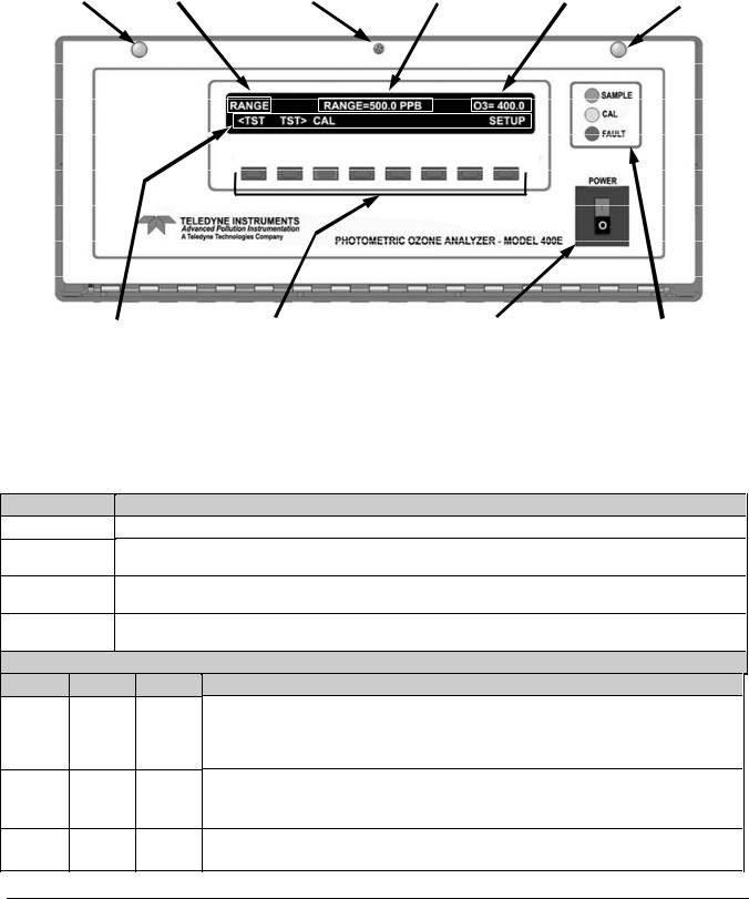
M400E Ozone Analyzer Operator’s Manual |
Getting Started |
3. GETTING STARTED
3.1. MODEL 400E ANALYZER LAYOUT
FASTENER |
MODE FIELD |
LOCKING SCREW |
MESSAGE FIELD CONCENTRATION FIELD FASTENER |
KEY DEFINITION FIELD |
KEYBOARD |
ON / OFF SWITCH |
STATUS LED’s |
Figure 3-1: M400E Front Panel Layout
Table 3-1: Front Panel Nomenclature
NAME
Mode Field
Message Field
Concentration
Field
Keypad
Definition Field
SIGNIFICANCE
Displays the name of the analyzer’s current operating mode
Displays a variety of informational messages such as warning messages, operational data, test function values and response messages during interactive tasks.
Displays the actual concentration of the sample gas currently being measured by the analyzer in the currently selected units of measure
Displays dynamic, context sensitive definitions for the row of keys just below the display.
STATUS LED’s
NAME |
COLOR |
STATE |
DEFINITION |
|
|
|
Off |
Unit is not operating in sample mode, iDAS is disabled. |
|
SAMPLE |
Green |
On |
Sample Mode active; Front Panel Display being updated; iDAS data being stored. |
|
Blinking |
Unit is operating in sample mode, front panel display being updated, iDAS hold-off mode is ON, |
|||
|
|
|||
|
|
|
iDAS disabled |
|
|
|
Off |
Auto Cal disabled |
|
CAL |
Yellow |
On |
Auto Cal enabled |
|
|
|
Blinking |
Unit is in calibration mode |
|
FAULT |
Red |
Off |
O3 warnings exist |
|
Blinking |
Warnings exist |
|||
|
|
04315 Rev. C1 |
11 |

Getting Started |
M400E Ozone Analyzer Operator’s Manual |
Cooling Fan |
Serial I/O LEDs |
Status Outputs |
Analog Outputs |
Sample Gas Inlet
Exhaust Gas
Outlet
Power Receptacle |
DCE – DTE Switch COM Port A |
COM Port B |
Control |
Serial Number |
|
(RS-232 Only) |
(RS-232 or RS-485) |
Inputs |
Tag |
Figure 3-2: M400E Rear Panel Layout – Basic Version
Cooling Fan |
Serial I/O LEDs |
Status Outputs |
Analog Outputs |
Sample Gas Inlet
Exhaust Gas
Outlet
Dry Air Inlet
Power Receptacle |
DCE – DTE Switch COM Port A |
COM Port B |
Control |
Serial Number |
|
(RS-232 Only) |
(RS-232 or RS-485) |
Inputs |
Tag |
Figure 3-3: M400E Rear Panel Layout with Internal Zero/Span (IZS) Option (OPT-51A)
12 |
04315 Rev. C1 |
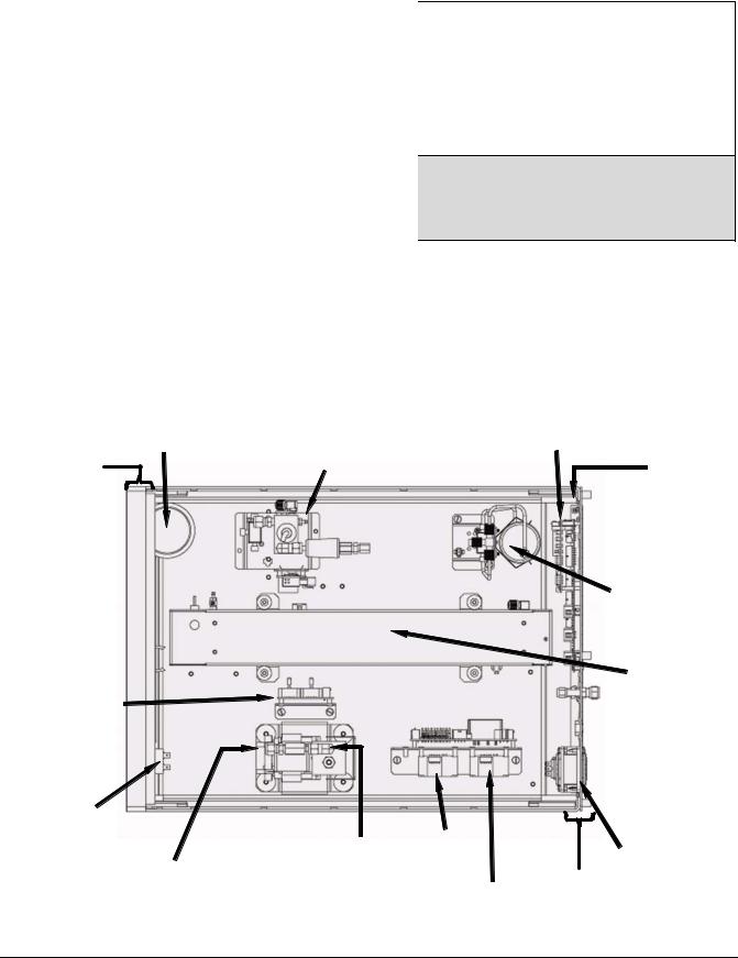
M400E Ozone Analyzer Operator’s Manual |
Getting Started |
Table 3-2: M400E Analyzer Gas Inlet/Outlet Nomenclature
|
REAR PANEL |
|
FUNCTION |
||
|
LABEL |
|
|||
|
|
|
|
||
|
SAMPLE |
|
Connect the source of sample gas here. |
||
|
|
|
|
|
|
|
EXHAUST |
|
Connect exhaust gas line here (must be <10 |
||
|
|
meters). |
|||
|
|
|
|
||
|
SPAN |
|
|
Connect the source of calibrated span gas here. |
|
|
ZERO AIR |
|
|
Connect the source of zero air here. |
|
|
DRY AIR |
|
|
Attach the source of dry air here (< -20ºc dew |
|
|
|
|
point). |
|
|
|
|
|
|
|
|
CONFIGURATION VARIATIONS
Calibration gasses are also inlet here on:
Base configuration and;
Analyzers with the internal zero/span valve option installed (OPT-51A)
All configurations
Only present with Zero/Span valves (OPT-50A)
Only present with Zero/Span valves (OPT-50A)
Only present with the internal zero/span option (OPT-51A)
|
Particulate Filter |
|
PC/104 Card |
|
|
IZS O3 |
Generator |
||
Front Panel |
Mother |
|||
(Optional) |
||||
Board |
||||
|
|
|
||
Measure /
Reference
Valve
Optical
Bench
Gas Flow
Sensor Assy
 Relay Board
ON/OFF |
|
|
|
SWITCH |
|
Power |
|
Critical Flow |
PS2 |
||
(+12 VDC) |
Receptacle |
||
Orifice |
|||
|
|
||
Pump Assy |
PS1 |
Rear Panel |
|
|
|||
|
(+5 VDC; 15VDC) |
|
Figure 3-4: M400E Internal Layout – Top View with IZS Option
04315 Rev. C1 |
13 |
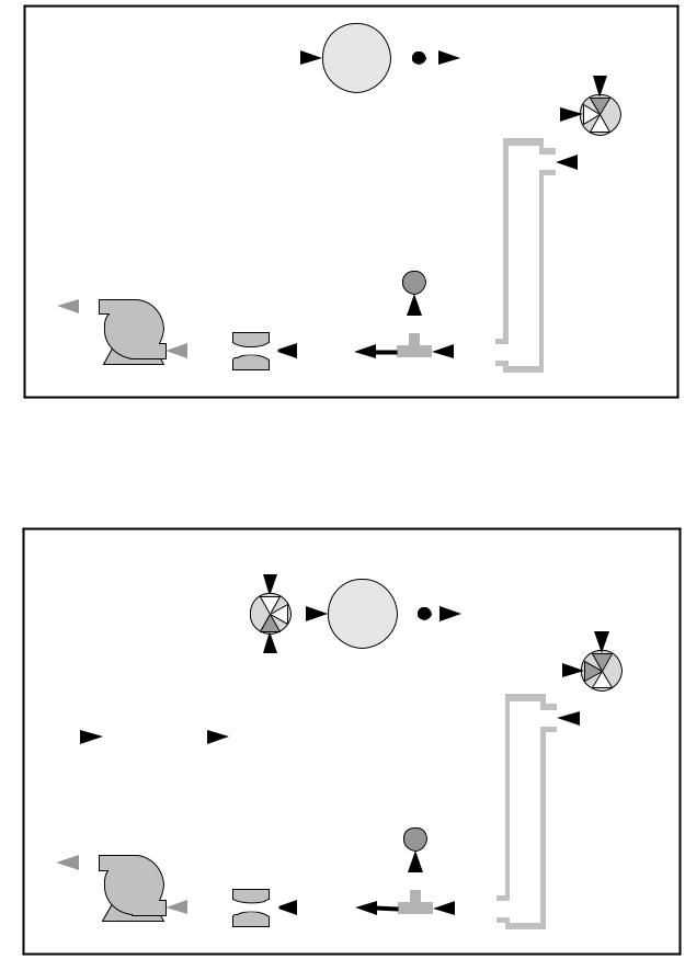
Getting Started |
|
|
|
|
|
|
|
|
|
M400E Ozone Analyzer Operator’s Manual |
|||||||||||||||||||||
|
|
|
|
|
|
|
|
|
|
|
|
|
|
|
|
|
|
|
|
|
|
|
|
|
|
|
|
|
|
|
|
|
|
|
|
|
|
|
|
|
|
|
|
|
|
|
|
|
|
|
|
|
|
|
|
|
|
|
|
|
|
|
|
|
|
|
|
|
|
|
|
|
|
|
|
|
|
|
|
|
|
|
|
|
|
|
|
|
|
|
|
|
|
|
|
|
|
|
|
|
|
|
|
|
|
|
|
|
|
|
|
|
|
|
|
|
|
|
|
|
|
|
|
|
|
|
|
|
|
|
|
|
|
|
|
|
|
|
|
|
|
|
|
|
|
|
|
|
|
|
|
|
|
|
|
|
|
|
|
|
|
|
|
|
|
|
|
|
|
|
|
|
|
|
|
|
|
|
|
|
|
|
|
|
|
|
|
|
|
|
|
|
|
|
|
|
|
|
|
|
|
|
|
|
|
|
|
|
|
|
|
|
|
|
|
|
|
|
|
|
|
|
|
|
|
|
|
|
|
|
|
|
|
|
|
|
|
|
|
|
|
|
|
|
|
|
|
|
|
|
|
|
|
|
|
|
|
|
|
|
|
|
|
|
|
|
|
|
|
|
|
|
|
|
|
|
|
|
|
|
|
|
|
|
|
|
|
|
|
|
|
|
|
|
|
|
|
|
|
|
|
|
|
|
|
|
|
|
|
|
|
|
|
|
|
|
|
|
|
|
|
|
|
|
|
|
|
|
|
|
|
|
|
|
|
|
|
|
|
|
|
|
|
|
|
|
|
|
|
|
|
|
|
|
|
|
|
|
|
|
|
|
|
|
|
|
|
|
|
|
|
|
|
|
|
|
|
|
|
|
|
|
|
|
|
|
|
|
|
|
|
|
|
|
|
|
|
|
|
|
|
|
|
|
|
|
|
|
|
|
|
|
|
|
|
|
|
|
|
|
|
|
|
|
|
|
|
|
|
|
|
|
|
|
|
|
|
|
|
|
|
|
|
|
|
|
|
|
|
|
|
|
|
|
|
|
|
|
|
|
|
|
|
|
|
|
|
|
|
|
|
|
|
|
|
|
|
|
|
|
|
|
|
|
|
|
|
|
|
|
|
|
|
|
|
|
|
|
|
|
|
|
|
|
|
|
|
|
|
|
|
|
|
|
|
|
|
|
|
|
|
|
|
|
|
|
|
|
|
|
|
|
|
|
|
|
|
|
|
|
|
|
|
|
|
|
|
|
|
|
|
|
|
|
|
|
|
|
|
|
|
|
|
|
|
|
|
|
|
|
|
|
|
|
|
|
|
|
|
|
|
|
|
|
|
|
|
|
|
|
|
|
|
|
|
|
|
|
|
|
|
|
|
|
|
|
|
|
|
|
|
|
|
|
|
|
|
|
|
|
|
|
|
|
|
|
|
|
|
|
|
|
|
|
|
|
|
|
|
|
|
|
|
|
|
|
|
|
|
|
|
|
|
|
|
|
|
|
|
|
|
|
|
|
|
|
|
|
|
|
|
|
|
|
|
|
|
|
|
|
|
|
|
|
|
|
|
|
|
|
|
|
|
|
|
|
|
|
|
|
|
|
|
|
|
|
|
|
|
|
|
|
|
|
|
|
|
|
|
|
|
|
|
|
|
|
|
|
|
|
|
|
|
|
|
|
|
|
|
|
|
|
|
|
|
|
|
|
|
|
|
|
|
|
|
|
|
|
|
|
|
|
|
|
|
|
|
|
|
|
|
|
|
|
|
|
|
|
|
|
|
|
|
|
|
|
|
|
|
|
|
|
|
|
|
|
|
|
|
|
|
|
|
|
|
|
|
|
|
|
|
|
|
|
|
|
|
|
|
|
|
|
|
|
|
|
|
|
|
|
|
|
|
|
|
|
|
|
|
|
|
|
|
|
|
|
|
|
|
|
|
|
|
|
|
|
|
|
|
|
|
|
|
|
|
|
|
|
|
|
|
|
|
|
|
|
|
|
|
|
|
|
|
|
|
|
|
|
|
|
|
|
|
|
|
|
|
|
|
|
|
|
|
|
|
|
|
|
|
|
|
|
|
|
|
|
|
|
|
|
|
|
|
|
|
|
|
Figure 3-5: M400E Pneumatic Diagram – Basic Unit
|
|
|
|
|
|
|
|
|
|
|
|
|
|
|
|
|
|
|
|
|
|
|
|
|
|
|
|
|
|
|
|
|
|
|
|
|
|
|
|
|
|
|
|
|
|
|
|
|
|
|
|
|
|
|
|
|
|
|
|
|
|
|
|
|
|
|
|
|
|
|
|
|
|
|
|
|
|
|
|
|
|
|
|
|
|
|
|
|
|
|
|
|
|
|
|
|
|
|
|
|
|
|
|
|
|
|
|
|
|
|
|
|
|
|
|
|
|
|
|
|
|
|
|
|
|
|
|
|
|
|
|
|
|
|
|
|
|
|
|
|
|
|
|
|
|
|
|
|
|
|
|
|
|
|
|
|
|
|
|
|
|
|
|
|
|
|
|
|
|
|
|
|
|
|
|
|
|
|
|
|
|
|
|
|
|
|
|
|
|
|
|
|
|
|
|
|
|
|
|
|
|
|
|
|
|
|
|
|
|
|
|
|
|
|
|
|
|
|
|
|
|
|
|
|
|
|
|
|
|
|
|
|
|
|
|
|
|
|
|
|
|
|
|
|
|
|
|
|
|
|
|
|
|
|
|
|
|
|
|
|
|
|
|
|
|
|
|
|
|
|
|
|
|
|
|
|
|
|
|
|
|
|
|
|
|
|
|
|
|
|
|
|
|
|
|
|
|
|
|
|
|
|
|
|
|
|
|
|
|
|
|
|
|
|
|
|
|
|
|
|
|
|
|
|
|
|
|
|
|
|
|
|
|
|
|
|
|
|
|
|
|
|
|
|
|
|
|
|
|
|
|
|
|
|
|
|
|
|
|
|
|
|
|
|
|
|
|
|
|
|
|
|
|
|
|
|
|
|
|
|
|
|
|
|
|
|
|
|
|
|
|
|
|
|
|
|
|
|
|
|
|
|
|
|
|
|
|
|
|
|
|
|
|
|
|
|
|
|
|
|
|
|
|
|
|
|
|
|
|
|
|
|
|
|
|
|
|
|
|
|
|
|
|
|
|
|
|
|
|
|
|
|
|
|
|
|
|
|
|
|
|
|
|
|
|
|
|
|
|
|
|
|
|
|
|
|
|
|
|
|
|
|
|
|
|
|
|
|
|
|
|
|
|
|
|
|
|
|
|
|
|
|
|
|
|
|
|
|
|
|
|
|
|
|
|
|
|
|
|
|
|
|
|
|
|
|
|
|
|
|
|
|
|
|
|
|
|
|
|
|
|
|
|
|
|
|
|
|
|
|
|
|
|
|
|
|
|
|
|
|
|
|
|
|
|
|
|
|
|
|
|
|
|
|
|
|
|
|
|
|
|
|
|
|
|
|
|
|
|
|
|
|
|
|
|
|
|
|
|
|
|
|
|
|
|
|
|
|
|
|
|
|
|
|
|
|
|
|
|
|
|
|
|
|
|
|
|
|
|
|
|
|
|
|
|
|
|
|
|
|
|
|
|
|
|
|
|
|
|
|
|
|
|
|
|
|
|
|
|
|
|
|
|
|
|
|
|
|
|
|
|
|
|
|
|
|
|
|
|
|
|
|
|
|
|
|
|
|
|
|
|
|
|
|
|
|
|
|
|
|
|
|
|
|
|
|
|
|
|
|
|
|
|
|
|
|
|
|
|
|
|
|
|
|
|
|
|
|
|
|
|
|
|
|
|
|
|
|
|
|
|
|
|
|
|
|
|
|
|
|
|
|
|
|
|
|
|
|
|
|
|
|
|
|
|
|
|
|
|
|
|
|
|
|
|
|
|
|
|
|
|
|
|
|
|
|
|
|
|
|
|
|
|
|
|
|
|
|
|
|
|
|
|
|
|
|
|
|
|
|
|
|
|
|
|
|
|
|
|
|
|
|
|
|
|
|
|
|
|
|
|
|
|
|
|
|
|
|
|
|
|
|
|
|
|
|
|
|
|
|
|
|
|
|
|
|
|
|
|
|
|
|
|
|
|
|
|
|
|
|
|
|
|
|
|
|
|
|
|
|
|
|
|
|
|
|
|
|
|
|
|
|
|
|
|
|
|
|
|
|
|
|
|
|
|
|
|
|
|
|
|
|
|
|
|
|
|
|
|
|
|
|
|
|
|
|
|
|
|
|
|
|
|
|
|
|
|
|
|
|
|
|
|
|
|
|
|
|
|
|
|
|
|
|
|
|
|
|
|
|
|
|
|
|
|
|
|
|
|
|
|
|
|
|
|
|
|
|
|
|
|
|
|
|
|
|
|
|
|
|
|
|
|
|
|
|
|
|
|
|
|
|
|
|
|
|
|
|
|
|
|
|
|
|
|
|
|
|
|
|
|
|
|
|
|
|
|
|
|
|
|
|
|
|
|
|
|
|
|
|
|
|
|
|
|
|
|
|
|
|
|
|
|
|
|
|
|
|
|
|
|
|
|
|
|
|
|
|
|
|
|
|
|
|
|
|
|
|
|
|
|
|
|
|
|
|
|
|
|
|
|
|
|
|
|
|
|
|
|
|
|
|
|
|
|
|
|
|
|
|
|
|
|
|
|
|
|
|
|
|
|
|
|
|
|
|
|
|
|
|
|
|
|
|
|
|
|
|
|
|
|
|
|
|
|
|
|
|
|
|
|
|
|
|
|
|
|
|
|
|
|
|
|
|
|
|
|
|
|
|
|
|
|
|
|
|
|
|
|
|
|
|
|
|
|
|
|
|
|
|
|
|
|
|
|
|
|
|
|
|
|
|
|
|
|
|
|
|
|
|
|
|
|
|
|
|
|
|
|
|
|
|
|
|
|
|
|
|
|
|
|
|
|
|
|
|
|
|
|
|
|
|
|
|
|
|
|
|
|
|
|
|
|
|
|
|
|
|
Figure 3-6: |
M400E Pneumatic Diagram with Internal Zero/Span (IZS) Option (OPT-51A) |
||||||||||||||||||||||||||||||||||
|
|
|
|
|
|
|
|
|
|
|
|
|
|
|
|
|
|
|
|
|
|
|
|
|
|
|
|
|
|
|
|
|
|
|
||
14 |
|
|
|
|
|
|
|
|
|
|
|
|
|
|
|
|
|
|
|
|
|
|
|
|
|
|
|
|
|
|
|
|
|
04315 Rev. C1 |
||
M400E Ozone Analyzer Operator’s Manual |
Getting Started |
3.2. UNPACKING THE M400E ANALYZER
CAUTION
General Safety Hazard
TO AVOID PERSONAL INJURY, ALWAYS USE TWO PERSONS TO LIFT AND CARRY
THE MODEL 400E.
1.Verify that there is no apparent external shipping damage. If damage has occurred, please advise the shipper first, then Teledyne Instruments.
2.Included with your analyzer is a printed record of the final performance characterization performed on your instrument at the factory. This record, titled Final Test and Validation Data Sheet (P/N 04314) is an important quality assurance and calibration record for this instrument. It should be placed in the quality records file for this instrument.
3.Carefully remove the top cover of the analyzer and check for internal shipping damage.
Remove the setscrew located in the top, center of the Front panel.
Remove the two screws fastening the top cover to the unit (one per side towards the rear).
Slide the cover backwards until it clears the analyzer’s front bezel.
Lift the cover straight up.
NOTE
Printed circuit assemblies (PCAs) are sensitive to electro-static discharges too small to be felt by the human nervous system. Failure to use ESD protection when working with electronic assemblies will void the instrument warranty.
See Chapter 12 for more information on preventing ESD damage.
CAUTION
Electrical Shock Hazard
NEVER DISCONNECT PCAS, WIRING HARNESSES OR ELECTRONIC SUBASSEMBLIES
WHILE UNDER POWER.
4.Inspect the interior of the instrument to make sure all circuit boards and other components are in good shape and properly seated.
5.Check the connectors of the various internal wiring harnesses and pneumatic hoses to make sure they are firmly and properly seated.
6.Verify that all of the optional hardware ordered with the unit has been installed. These are listed on the paperwork accompanying the analyzer.
04315 Rev. C1 |
15 |

Getting Started |
M400E Ozone Analyzer Operator’s Manual |
3.2.1.1. Ventilation Clearance
Whether the analyzer is set up on a bench or installed into an instrument rack, be sure to leave sufficient ventilation clearance.
Table 3-3: Ventilation Clearance
AREA |
MINIMUM REQUIRED CLEARANCE |
Back of the instrument |
4 in. |
Sides of the instrument |
1 in. |
|
|
Above and below the instrument |
1 in. |
Various rack mount kits are available for this analyzer. See Section 5.1 of this manual for more information.
3.3. ELECTRICAL CONNECTIONS
3.3.1. POWER CONNECTION
Attach the power cord to the analyzer and plug it into a power outlet capable of carrying at least 10 A current at your AC voltage and that it is equipped with a functioning earth ground.
CAUTION
Electrical Shock Hazard
HIGH VOLTAGES ARE PRESENT INSIDE THE ANALYZERS CASE
POWER CONNECTION MUST HAVE FUNCTIONING GROUND CONNECTION.
DO NOT DEFEAT THE GROUND WIRE ON POWER PLUG.
TURN OFF ANALYZER POWER BEFORE DISCONNECTING OR
CONNECTING ELECTRICAL SUBASSEMBLIES.
DO NOT OPERATE WITH COVER OFF.
CAUTION
General Safety Hazard
THE M400E ANALYZER CAN BE CONFIGURED FOR BOTH 100-130 V AND
210-240 V AT EITHER 50 OR 60 HZ.
TO AVOID DAMAGE TO YOUR ANALYZER, MAKE SURE THAT THE AC POWER VOLTAGE MATCHES THE VOLTAGE INDICATED ON THE ANALYZER’S SERIAL NUMBER LABEL TAG (SEE FIGURE 3-2) BEFORE PLUGGING THE M400E INTO LINE POWER.
16 |
04315 Rev. C1 |

M400E Ozone Analyzer Operator’s Manual |
Getting Started |
3.3.2. ANALOG OUTPUT CONNECTIONS
The M400E is equipped with several analog output channels accessible through a connector on the back panel of the instrument (see Figure 3-2).
Channels A1 and A2 output a signal that is proportional to the O3 concentration of the sample gas.
The default analog output voltage setting of these channels is 0 to 5 VDC with a reporting range of 0 to 500 ppb.
An optional Current Loop output is available for each.
The output labeled A4 is special. It can be set by the user to output any one a variety of diagnostic test functions.
The default analog output voltage setting of these channels is also 0 to 5 VDC.
See Section 7.4.6 for a list of available functions and their associated reporting range.
There is no optional Current Loop output available for Channel A4.
To access these signals attach a strip chart recorder and/or data-logger to the appropriate analog output connections on the rear panel of the analyzer. Pin-outs for the analog output connector are:
|
|
ANALOG OUT |
|
|
|
|
A1 |
A2 |
A3 |
A4 |
|
+ - |
+ - + |
- |
+ - |
|
|
|
|
|
|
|
|
|
|
|
|
|
|
|
|
|
|
|
|
|
|
|
|
Figure 3-7: |
M400E Analog Output Connector |
|
|
|||
|
|
|
|
Table 3-4: Analog Output Pin Outs |
|
|
||||
|
|
|
|
|
|
|
|
|
|
|
|
Pin |
|
Analog Output |
|
Standard Voltage |
|
Current |
|||
|
|
|
Output |
|
Loop Option |
|||||
|
|
|
|
|
|
|
|
|||
1 |
|
|
A1 |
|
|
V Out |
|
I Out + |
||
|
|
|
|
|
|
|
|
|
|
|
2 |
|
|
|
Ground |
|
I Out - |
||||
|
|
|
|
|
|
|||||
|
|
|
|
|
|
|
|
|
|
|
3 |
|
|
A2 |
|
|
V Out |
|
I Out + |
||
4 |
|
|
|
|
Ground |
|
I Out - |
|||
|
|
|
|
|
|
|||||
|
5 |
|
|
A3 |
|
|
NOT USED |
|
||
|
6 |
|
|
|
|
|
||||
|
|
|
|
|
|
|
|
|
|
|
7 |
|
|
A4 |
|
|
V Out |
|
Not Available |
||
8 |
|
|
|
|
Ground |
|
Not Available |
|||
|
|
|
|
|
|
|||||
To change the settings for the analog output channels, see Section 7.4
04315 Rev. C1 |
17 |
Getting Started |
M400E Ozone Analyzer Operator’s Manual |
3.3.3. CONNECTING THE STATUS OUTPUTS
The status outputs report analyzer conditions via optically isolated NPN transistors, which sink up to 50 mA of DC current. These outputs can be used interface with devices that accept logic-level digital inputs, such as programmable logic controllers (PLCs). Each Status bit is an open collector output that can withstand up to 40 VDC. All of the emitters of these transistors are tied together and available at D.
NOTE
Most PLC’s have internal provisions for limiting the current that the input will draw from an external device. When connecting to a unit that does not have this feature, an external dropping resistor must be used to limit the current through the transistor output to less than 50 mA. At 50 mA, the transistor will drop approximately 1.2V from its collector to emitter.
The status outputs are accessed via a 12-pin connector on the analyzer’s rear panel labeled STATUS (see Figure 3-2). Pin-outs for this connector are:
STATUS
|
|
|
|
|
|
|
|
|
|
|
|
|
|
|
|
|
|
|
|
|
|
|
|
|
|
|
|
|
|
|
|
|
1 |
|
2 |
3 4 |
5 |
6 7 8 D |
+ |
|
|
||
|
|
|
||||||||
|
|
|
||||||||
SYSTEM OK |
CONC VALID |
HIGH RANGE |
ZERO CAL |
SPAN CAL |
DIAG MODE |
|
|
|
|
|
|
|
|
|
|||||||
|
|
|
|
|||||||
|
Figure 3-8: |
Status Output Connector |
||
|
Table 3-5: Status Output Pin Assignments |
|||
|
|
|
|
|
OUTPUT # |
STATUS |
|
CONDITION |
|
DEFINITION |
|
|||
|
|
|
||
1 |
SYSTEM OK On if no faults are present. |
|||
2 |
CONC VALID |
On if O3 concentration measurement is valid. |
||
If the O3 |
concentration measurement is invalid, this bit is OFF. |
|||
|
|
|||
3HIGH RANGE On if unit is in high range of DUAL or AUTO Range Modes.
4ZERO CAL On whenever the instrument is in CALZ mode.
5SPAN CAL On whenever the instrument is in CALS mode.
6DIAG MODE On whenever the instrument is in DIAGNOSTIC mode.
7 & 8 |
Unassigned |
|
|
D |
Emitter BUSS |
The emitters of the transistors on pins 1 to 8 are bussed together. |
|
|
|
|
|
|
|
Spare |
|
+ |
DC Power |
+ 5 VDC, 300 mA source (combined rating with Control Output, if used). |
|
|
|
|
|
|
|
Digital Ground |
The ground level from the analyzer’s internal DC power supplies. |
|
|
||
|
|
||
18 |
04315 Rev. C1 |
Loading...